Table of Contents
Advertisement
Quick Links
Owner's Manual
NetDirector
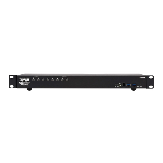
Rack-Mount 4K/60 Hz
HDMI KVM Switch
Este manual está disponible en español en la página de Tripp Lite: tripplite.com
Ce manuel est disponible en français sur le site Web de Tripp Lite : tripplite.com
WARRANTY REGISTRATION
Register your product today and be
automatically entered to win an ISOBAR
surge protector in our monthly drawing!
tripplite.com/warranty
1111 W. 35th Street, Chicago, IL 60609 USA • tripplite.com/support
with Audio
8-Port Model: B024-H4U08
16-Port Model: B024-H4U16
Copyright © 2021 Tripp Lite. All rights reserved.
1U
®
®
1
Advertisement
Table of Contents

Subscribe to Our Youtube Channel
Related Manuals for Tripp Lite NetDirector B024-H4U16


Summary of Contents for Tripp Lite NetDirector B024-H4U16
- Page 1 8-Port Model: B024-H4U08 16-Port Model: B024-H4U16 Este manual está disponible en español en la página de Tripp Lite: tripplite.com Ce manuel est disponible en français sur le site Web de Tripp Lite : tripplite.com WARRANTY REGISTRATION Register your product today and be automatically entered to win an ISOBAR ®...
-
Page 2: Table Of Contents
Table of Contents 1. FCC Information 9. OSD Operation 9.1 OSD Login 2. User Notice 9.2 OSD Hotkey 3. Package Contents 9.3 OSD Main Screen 4. Features 9.4 OSD Main Screen Headings 5. System Requirements 9.5 OSD Navigation 5.1 Console 9.6 OSD Functions 5.2 Computers 9.6.1 F1: Go To... - Page 3 Table of Contents 12. RS-232 Operation 14. Appendix 12.1 Setup 14.1 B024-H4U08 and B024-H4U16 Connection Tables 12.2 RS-232 Pin Assignments 14.1.1 B024-H4U08 (First Level) + 12.3 Console Login: HyperTerminal 46 B024-H4U08 (Second Level) 12.4 RS-232 Commands 14.1.2 B024-H4U16 (First Level) + 12.4.1 Verification B024-H4U16 (Second Level) 12.4.2 Login...
-
Page 4: Fcc Information
Operation of this equipment in a residential area is likely to cause harmful interference in which case the user will be required to correct the interference at his own expense. The user must use shielded cables and connectors with this equipment. Any changes or modifications to this equipment not expressly approved by Tripp Lite could void the user’s authority to operate this equipment. 2. User Notice All information, documentation, and specifications contained in this manual are subject to change without prior notification by the manufacturer. The manufacturer makes no representations or warranties, either expressed or... -
Page 5: Features
4. Features • One USB console controls up to eight (B024-H4U08) or sixteen (B024-H4U16) DisplayPort interface computers and two additional USB 3.0 peripheral devices. • Cascadable to three levels – controls up to 512 computers (B024-H4U08) or to two levels--up to 256 computers (B024-H4U16). -
Page 6: System Requirements
5. System Requirements 5.1 Console • HDMI monitor capable of the highest possible resolution in the installation Note: For multi-display installations, multiple monitors are required. See 7.3.4 Multi-Display Installation for details. • USB mouse • USB keyboard • Speakers (optional) 5.2 Computers •... -
Page 7: Components
5. System Requirements 5.5 Components Front View B024-H4U08 B024-H4U16 No. Component Description Port Selection For manual port selection: Pushbuttons • Press a port selection pushbutton for less than two seconds to bring the KVM, USB hub and audio focus to the computer attached to its corresponding port. •... - Page 8 5. System Requirements No. Component Description Firmware During normal operation and while performing a firmware upgrade, this switch should be Upgrade in the NORMAL position. If a firmware upgrade operation does not complete successfully, this switch is used to perform a firmware upgrade recovery. See section 13.6 Firmware Recovery Switch Upgrade Recovery for details. Audio Jack The cables from your main speakers plug in here. Note: The speakers plugged into the front-panel audio jack have priority over those in the rear panel. Firmware The firmware upgrade cable that transfers the firmware upgrade data from the Upgrade Port...
- Page 9 5. System Requirements Rear View B024-H4U08 1 2 3 B024-H4U16 1 2 3 No. Component Description Grounding The grounding wire used to ground the switch attaches here. Terminal Power Jack The power adapter cable plugs in here. Audio Jack The cables from your main speakers plug in here. Note: The speakers plugged into the front panel audio jack have priority over those plugged in here.
-
Page 10: Important Safety Instructions
• To help protect the system from unexpected transient increases and decreases in electrical power, use a Tripp Lite Surge Protector, Line Conditioner, or Uninterruptible Power Supply (UPS). -
Page 11: Rack-Mounting Safety Instructions
6. Important Safety Instructions • If the following conditions occur, unplug the device from the wall outlet and bring it to qualified service personnel for repair: – The power cord or plug has become damaged or frayed. – Liquid has been spilled into the device. – The device has been exposed to rain or water. – The device has been dropped or the cabinet has been damaged. –... -
Page 12: Installation
7. Installation The B024-H4U08 and B024-H4U16 can be stacked on a desktop or rack mounted at the front or rear of a rack. Notes: • Allow at least 2 inches (5.1 cm) on each side for adequate ventilation and 5 inches (12.7 cm) at the rear for power cord and cable clearance. - Page 13 7. Installation Use the M3 x 6 Phillips hex head screws supplied with the rack mounting kit to attach the rack mounting brackets onto the sides near the front of the unit. Place the KVM switch in the rack. Position it so that the holes in the mounting brackets line up with the holes in the rack.
-
Page 14: Rear Rack-Mounting
7. Installation 7.2.2 Rear Rack-Mounting Remove each of the screws from the left and right sides near the rear of the unit. Use the M3 x 6 Phillips hex head screws supplied with the rack mounting kit to attach the rack mounting brackets onto the sides near the rear of the unit. - Page 15 7. Installation Place the KVM switch in the rack. Position it so that the holes in the mounting brackets line up with the holes in the rack. Secure the mounting brackets to the rear of the rack.
-
Page 16: Kvm Switch Installation
7. Installation 7.3 KVM Switch Installation 7.3.1 Single-Stage Installation To set up the console KVM switch, refer to the following steps and installation diagram. Note: B024-H4U16 model shown. The port locations are the same for the B024-H4U08, except for the number of KVM ports. Front Rear HDMI Cable... -
Page 17: Two-Stage Cascade Installation
7. Installation At the other end of the cables from step 5, plug the DisplayPort cable, USB 3.0 cable, and audio cables into their respective ports on the computer. Repeat steps 5 and 6 for other PC systems you are installing. (Optional) Plug your USB peripherals into the USB Type-A ports in the USB 3.1 Gen1 Peripheral Hub located on the unit’s front panel. -
Page 18: Three-Stage Cascade Installation
7. Installation Make sure that power to all the devices you will be connecting—including all preexisting devices on the installation—has been turned off. Use the provided cable sets (HDMI cable, USB 3.0 cable, and audio cable) to connect the First Stage unit to the console ports of the Second Stage unit. - Page 19 7. Installation USB HDMI KVM Cable Set USB HDMI KVM Cable Set Once you have finished cabling up (see section 7.3.2 Two-Stage Cascade Installation), power up according to the following sequence: For each Third-Stage unit, plug the power adapter cable into the switch’s Power Jack, then plug the power adapter into an AC source.
-
Page 20: Multi-Display Installation
7. Installation 7.3.4 Multi-Display Installation The B024-H4U08 and B024-H4U16 multi-display feature allows you to stack up to 8 units in a dual/triple/quad-display/ multi-display installation to control up to seven (B024-H4U08) or fifteen (B024-H4U16) computers at once. This installation requires slightly different cabling than the standard cascade and offers an extra level of switching flexibility for multiple-monitor installations where each computer is equipped with multiple video cards. Note: In a multi-display installation, the B024-H4U08 can only be connected to B024-H4U08 units, and the B024-H4U16 can only be connected to B024-H4U16 units. -
Page 21: Grouping Ports Into Vertical Channels
7. Installation 7.3.5 Grouping Ports into Vertical Channels Once the cables have been connected and multi-display mode has been selected in the OSD, the KVM will auto-detect the channels and display modes. Users can then assign them a channel number as the port name so all the Port 1s become Channel 1, all the Port 2s become Channel 2, ... -
Page 22: Basic Operation
8. Basic Operation 8.1 Hot Plugging The B024-H4U08 and B024-H4U16 KVMs support hot-plugging where components can be removed and added back into the installation by unplugging their cables from the ports without needing to shut the unit down. In order for hot plugging to work properly, the procedures described below must be followed: 8.1.1 Hot Plugging KVM Ports In order for the OSD menus to correspond to KVM port changes, you must manually reconfigure the OSD to reflect the... -
Page 23: Powering Off And Restarting The Kvm
8. Basic Operation 8.4 Powering Off and Restarting the KVM If it becomes necessary to power off a KVM switch, do the following before restarting it: Unplug the KVM from its power source. Shut down all computers that are attached to it. Note: Unplug the power cords of any computers that have the Keyboard Power On function. Otherwise, the KVM will continue to receive power from the computers. -
Page 24: Osd Operation
9. OSD Operation The on-screen display (OSD) is a mouse- and keyboard-enabled, menu-driven method to handle computer control and switching operations. All procedures start from the OSD main screen. 9.1 OSD Login The OSD incorporates a two-level (administrator/user) password system. Before the OSD main screen displays, a login screen appears requiring a password. If this is the first time the OSD is used, or if the password function has not been set, simply press [Enter]. -
Page 25: Osd Main Screen
9. OSD Operation 9.3 OSD Main Screen When you invoke the OSD, a screen similar to the one below appears: Notes: • The diagram depicts the administrator’s main screen. The user main screen does not show the F4 and F6 functions, since these are reserved for the administrator and cannot be accessed by users. -
Page 26: Osd Navigation
9. OSD Operation 9.5 OSD Navigation • To dismiss the menu and deactivate OSD, click at the upper right corner of the OSD window or press [Esc]. • To log out, click at the left of the main screen, or press [F8]. •... -
Page 27: F2: List
9. OSD Operation 9.6.2 F2: List Clicking or pressing [F2] activates the List function. This function lets you broaden or narrow the scope of which ports the OSD displays on the main screen. The submenu choices and their meanings are provided in the table below. Choice Meaning Lists all ports in the installation that have been set accessible by the administrator for... -
Page 28: F3: Set
9. OSD Operation 9.6.3 F3: Set Clicking or pressing [F3] activates the Set function. This function allows the administrator and each user to set up their own working environment. A separate profile for each is stored by the OSD and is activated according to the username that was provided during login. To change a setting: Click it or move the highlight bar to it, then press [Enter]. After you select an item, a submenu with further choices appears. - Page 29 9. OSD Operation Setting Function Scan Duration Determines how long the focus dwells on each port as it cycles through the selected ports in Auto Scan mode (see 9.6.7 F7: Scan). Key in a value from 1 to 255 seconds, then press [Enter].
-
Page 30: F4: Admin
9. OSD Operation 9.6.4 F4: Admin Clicking or pressing [F4] activates Admin function. F4 is an administrator-only function. It allows the administrator to configure and control the overall operation of the OSD. To change a setting, click on the settings item you want to configure, or use the up and down arrow keys to move the highlight bar to it and press [Enter]. After you select an item, a submenu with further choices appears. Click an item, or move the highlight bar to it then press [Enter]. A check mark ( √ ) appears before the selected item so that you know which one it is. The settings are explained in the following table:... - Page 31 9. OSD Operation Setting Function Set User Login This function is used to set usernames and passwords for the administrator and users: 1. Usernames and passwords for one administrator and four users can be set. 2. After you select the administrator field or one of the user fields, a field that allows you to key in the username and password appears. Usernames and passwords can be from 1 to 16 characters long and can consist of any combination of letters and numbers (A–Z, 0–9) and some additional keys (* ( ) + : - , ?.
- Page 32 9. OSD Operation Setting Function Set Quick View Ports This function lets the administrator select which ports to include as quick view ports. • To select/deselect a port as a quick view port, use the navigation keys to move the highlight bar to it and press [Spacebar].
-
Page 33: F5: Skp
9. OSD Operation 9.6.5 F5: SKP Clicking or pressing [F5] invokes Skip (SKP) mode. This function lets you easily skip backward or forward and switch the console focus from the currently active computer port to the previous or next accessible one. Note: Mouse emulation must be enabled for Skip mode to work. -
Page 34: F6: Brc
9. OSD Operation 9.6.6 F6: BRC F6 is an administrator-only function. Clicking or pressing [F6] invokes Broadcast (BRC) mode. When this function is in effect, commands sent from the console are broadcast to all available computers on the installation. This function is particularly useful for operations that need to be performed on multiple computers, such as performing a systemwide shutdown, installing or upgrading software, etc While BRC mode is in effect: •... -
Page 35: F7: Scan
9. OSD Operation 9.6.7 F7: Scan Clicking or pressing [F7] invokes Auto Scan mode. This function allows you to automatically switch among the available computers at regular intervals so that their activity can be monitored without the inconvenience of switching yourself. Note: Mouse emulation must be enabled for Auto Scan to work. -
Page 36: F8: Logout
9. OSD Operation 9.6.8 F8: Logout Clicking or pressing [F8] logs you out of OSD control of the computers and blanks the console screen. This is different from simply pressing [Esc] when you are at the main screen to deactivate the OSD. With this function you must log in all over again to regain access to the OSD, whereas with [Esc], all you have to do to reenter the OSD is tap the OSD hotkey. -
Page 37: Hotkey Operation
10. Hotkey Operation 10.1 Hotkey Port Control Hotkey port control allows you to provide KVM focus to a particular computer directly from the keyboard. The B024-H4U08 and B024-H4U16 provides the following hotkey port control features: • Selecting the Active Port •... -
Page 38: Select The Active Port
10. Hotkey Operation 10.3 Select the Active Port Each KVM port is assigned a port ID (see section 8.3 Port ID Numbering). You can directly access any computer on the installation with a hotkey combination that specifies the port ID of the KVM port that a computer is connected to. To access a computer using hotkeys: Invoke HSM with the [Num Lock] + [-] or [Ctrl] + [F12] combination. Key in the port ID. -
Page 39: Skip Mode
10. Hotkey Operation 10.5 Skip Mode This feature allows you to switch between computers in order to monitor them manually. You can dwell on a particular port for as long as you like–as opposed to auto-scanning, which automatically switches after a fixed interval. To invoke Skip mode, key in the following hotkey combination: Enable mouse emulation (see 10.13 Mouse Emulation Control). Invoke HSM with the [Num Lock] + [-] or [Ctrl] + [F12] combination. -
Page 40: Hsm Hotkey Control
10. Hotkey Operation 10.8 HSM Hotkey Control The HSM Hotkey (see “Hotkey” in the table in section 9.6.3 F3: Set) can be toggled between [Num Lock] + [-], and [Ctrl] + [F12]. To toggle the HSM Hotkey: Invoke HSM with the [Num Lock] + [-] or [Ctrl] + [F12] combination. Press [H]. -
Page 41: Edid Mode
10. Hotkey Operation 10.12 EDID Mode To configure an EDID mode for the KVM: Invoke HSM with the [Num Lock] + [-] or [Ctrl] + [F12] combination. Press [V]. Key in [1], [2], [3], or [4]. The Function of [1], [2], [3], and [4] keys is listed in the following table: Description Sets the switch to read DisplayPort monitor’s EDID (Default) Default monitor’s EDID 1920 x 1080 @ 60 Hz... - Page 42 10. Hotkey Operation Function [V] [n] [Enter] Sets EDID Mode. • n = 1, read DisplayPort monitor’s EDID. • n = 2, default EDID mode (full HD 1920 x 1080 @ 60 Hz. [P] [n] [Enter] Sets the KVM switching mode. n = 1, sets the KVM to Normal Switching Mode.
-
Page 43: Keyboard Emulation
11. Keyboard Emulation 11.1 Mac Keyboard The PC-compatible (101/104 key) keyboard can emulate the functions of the Mac keyboard. The emulation mappings are listed in the table below. PC Keyboard Mac Keyboard [Shift] Shift [Ctrl] Ctrl [Ctrl] [1] [Ctrl] [2] [Ctrl] [3] [Ctrl] [4] [Alt]... -
Page 44: Sun Keyboard
11. Keyboard Emulation 11.2 Sun Keyboard The PC-compatible (101/104 key) keyboard can emulate the functions of the Sun keyboard when the Control key [Ctrl] is used in conjunction with other keys. The corresponding functions are shown in the table below. PC Keyboard Sun Keyboard [Ctrl] [T]... -
Page 45: Operation
12. RS-232 Operation The KVM’s built-in bi-directional RS-232 serial interface allows system control through a high-end controller or PC. RS-232 serial operations in the KVM installation are managed via HyperTerminal sessions on systems that are running Windows. In order to use this feature to send commands to the KVM, you must first download and install a HyperTerminal application. 12.1 Setup Install a HyperTerminal application on a computer that is not part of the installation, which will be used to control the switch via the RS-232 connection. -
Page 46: Console Login: Hyperterminal
12. RS-232 Operation 12.3 Console Login: HyperTerminal Once a physical connection from the computer to the KVM switch has been made, you can establish a HyperTerminal session. Open the HyperTerminal application, configure the port settings for COM1 port, then click OK. Bits per Second: 19200, Data Bits: 8, Parity: None, Stop bits: 1, Flow Control: None. After configuring the port settings you must enable serial control on the switch by typing the command: Open + [Enter]. -
Page 47: Commands
12. RS-232 Operation 12.4 RS-232 Commands After you login via HyperTerminal (see 12.3 Console Login: HyperTerminal), use the instructions below to send RS-232 commands to control the switch from the computer. When RS-232 control is enabled via the Open + [Enter] command, the KVM’s front panel pushbuttons, OSD, hotkeys and remote control commands will be disabled until the RS-232 control is disabled. -
Page 48: Logout
12. RS-232 Operation 12.4.3 Logout The Logout commands allows you to log out of the KVM and close the RS-232 link. Use the Formula → to set Parameters → to create a Command. Formula Command + [Enter] Parameters Command Description Logout Logout command Enter Description Enter Enter and send out command Logout Command The formula for the Logout command is as follows: Command + [Enter]... -
Page 49: Set Baud Rate
12. RS-232 Operation 12.4.5 Set Baud Rate The Set Baud Rate command allows you to configure the baud rate setting for the serial port connection. The default baud rate is 19200. Use the Formula → to set Parameters → to create a Command. Formula Command + Control + [Enter] Parameters Command Description baud Baud rate command Control Description 19200 Set baud rate to 19200 (Default) 38400 Set baud rate to 38400 9600 Set baud rate to 9600 Enter... -
Page 50: Hotkey Setting
12. RS-232 Operation Switch Port Command The available formula for the Switch Port command is as follows: Command + Control + [Enter] For example, to switch to port 2, type the following: sw i02 [Enter] Note: The Control command can be skipped and the default value will be used. 12.4.7 Hotkey Setting The Hotkey Setting command allows you to change the hotkey used to invoke the HSM (Hotkey Setting Mode). -
Page 51: Osd Hotkey
12. RS-232 Operation 12.4.8 OSD Hotkey The OSD Hotkey command allows you to change the hotkey used to invoke the OSD. The default hotkey is [Scroll][Scroll]. Use the Formula → to set Parameters → to create a Command. Formula Command + Control + [Enter] Parameters Command Description osdkey OSD Hotkey command Control Description scroll... -
Page 52: Restore Default Settings
12. RS-232 Operation USB Reset Command The available formula for the USB Reset command is as follows: Command + Control + [Enter] For example, to reset the USB connection, type the following: usbreset on [Enter] 12.4.10 Restore Default Settings The Restore Default Settings command allows you to reset all of the KVM’s settings back to the default. The default setting is OFF. -
Page 53: Kvm Status
12. RS-232 Operation Firmware Upgrade Command The available formula for the Firmware Upgrade command is as follows: Command + Control + [Enter] For example, to enable firmware upgrade mode, type the following: upgrade on [Enter] 12.4.12 KVM Status The KVM Status command allows you to display read-only information about the KVM’s current configuration status. The default setting is off. Use the Formula → to set Parameters → to create a Command. Formula Command + Control + [Enter] Parameters Command Description... -
Page 54: Edid Mode
12. RS-232 Operation 12.4.13 EDID Mode The EDID Mode command allows you to set EDID mode for the KVM. Use the Formula → to set Parameters → to create a Command. Formula Command + Control + [Enter] Parameters Command Description edid Set EDID Mode command Control Description port1 Set to display A (DisplayPort monitor) EDID default Set to default EDID Enter... -
Page 55: Firmware Management Utility
13. Firmware Management Utility 13.1 Downloading the Firmware To download the firmware: From a computer that is not part of your KVM installation, go to tripplite.com and choose the model name that relates to your device. A list of available firmware appears. Choose the firmware that you wish to install (usually the most recent) and download it to your computer. 13.2 Preparation To prepare for the firmware upgrade, do the following: Use the Firmware Upgrade Cable provided with this unit to connect a COM port on your computer to the Firmware Upgrade Port of your switch. -
Page 56: Starting The Upgrade
13. Firmware Management Utility 13.3 Starting the Upgrade To upgrade the firmware: Run the downloaded firmware upgrade package file, either by double clicking the file icon or by opening a command line and entering the full path to it. The Firmware Upgrade Utility welcome screen will appear: Note: The screens shown in this section are for reference only. The wording and layout of the actual Firmware Upgrade Utility may vary slightly from these examples. - Page 57 13. Firmware Management Utility When selecting a device in the list, its description appears in the Device List panel. Click Next to perform the upgrade. If you enabled Check Firmware Version, the Utility compares the device’s firmware level with that of the upgrade files. If it finds that the device’s version is higher than the upgrade version, a dialog box will appear informing you of the situation and offering you the option to continue or cancel. If you didn’t enable Check Firmware Version, the Utility installs the upgrade files without checking whether they are a higher level or not. As the upgrade proceeds, status messages appear in the Status Messages panel and the progress toward completion is shown on the Progress bar.
-
Page 58: Upgrade Successful
13. Firmware Management Utility 13.4 Upgrade Successful After the upgrade has completed, a screen will appear to inform you that the procedure was successful. Click Finish to close the Firmware Upgrade Utility. After a successful completion, the switches will exit Firmware Upgrade Mode and reset. 13.5 Upgrade Failed If the Upgrade Succeeded screen does not appear, the upgrade failed to complete successfully. -
Page 59: Osd Configuration Backup/Restore
13. Firmware Management Utility 13.7 OSD Configuration Backup/Restore The Firmware Management Utility lets you back up the current OSD configuration of the KVM and restore it when necessary. Storing the OSD configuration settings is useful when deploying more than one installation that uses the same settings. 13.7.1 Backup To store a backup file to a local computer: Make sure your computer is connected to the KVM (see 13.2 Preparation and follow steps 1–3). When you have selected the F4 Admin function, scroll down to OSD Config Backup / Restore. Press [Enter], then select Enable to invoke OSD Config Backup / Restore mode. Run the Firmware Management Utility. In the dialog box, choose “OSD Configuration Backup/Restore,” then click Next. In the window that appears, click Connect Device. In the Password field, key in a password for the file. -
Page 60: Restore
13. Firmware Management Utility 13.7.2 Restore Follow these steps to restore a backup file from a local computer: Perform steps 1 to 3 in 13.7.1 Backup. Click Restore to recover an OSD configuration stored in the local computer. If you have previously set a password for this feature, enter the password in the provided field before clicking Restore. A confirmation window will appear. Click Yes to proceed. Browse for the OSD configuration file you want to use and click Restore. Make sure the backup file is in the local computer. A confirmation window appears when the restore process is done and successful. Click OK to close it. 14. Appendix 14.1 B024-H4U08 and B024-H4U16 Connection Tables The following tables indicate the relationship between the number of Primary View (PV) units and the number of computers that they control: 14.1.2 B024-DPU16 (First Level) + 14.1.1 B024-H4U08 (First Level) +... - Page 61 14. Appendix 14.1.3 B024-H4U08 (First Level) + B024-H4U08 (Second Level) Computers Computers 1 – 8 260 – 267 8 – 15 267 – 274 15 – 22 274 – 281 22 – 29 281 – 288 29 – 36 288 – 295 36 –...
-
Page 62: B024-H4U08 (Third Level)
14. Appendix 14.2 Specifications B024-H4U08 B024-H4U16 Direct Computer Connections 512 (via Cascade) 256 (via Cascade) Port Selection OSD, Hotkey, Pushbutton, RS-232 Commands 1 x USB Type-A, Female Video 1 x HDMI, Female Console Ports Mouse 1 x USB Type-A, Female Speakers 2 x 3.5 mm Audio Jack, Female (Green;... -
Page 63: Administrator Login Failure
14. Appendix 14.3 Administrator Login Failure If you are unable to perform an Administrator login (e.g. because the username/password information has become corrupted or you have forgotten it), you can clear the login information with the following procedure: Power off the KVM and remove its housing. Short the jumper labeled DEFAULT PASSWORD. Power on the switch. -
Page 64: Warranty And Product Registration
15. Warranty and Product Registration 3-Year Limited Warranty TRIPP LITE warrants its products to be free from defects in materials and workmanship for a period of three (3) years from the date of initial purchase. TRIPP LITE’s obligation under this warranty is limited to repairing or replacing (at its sole option) any such defective products.
Need help?
Do you have a question about the NetDirector B024-H4U16 and is the answer not in the manual?
Questions and answers