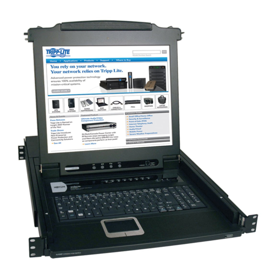
Tripp Lite B020-016-17-IP Owner's Manual
Console kvm switch with ip access
Hide thumbs
Also See for B020-016-17-IP:
- Owner's manual (45 pages) ,
- Owner's manual (45 pages) ,
- Specification sheet (3 pages)
Table of Contents
Advertisement
Quick Links
Download this manual
See also:
Owner's Manual
Advertisement
Table of Contents

Related Manuals for Tripp Lite B020-016-17-IP


Summary of Contents for Tripp Lite B020-016-17-IP
- Page 1 Owner’s Manual Console KVM Switch with IP Access Model # B020-016-17-IP 1111 W. 35th Street, Chicago, IL 60609 USA www.tripplite.com/support Copyright © 2011 Tripp Lite. All rights reserved. All trademarks are the property of their respective owners.
-
Page 2: Table Of Contents
Table of Contents 1. FCC Information 7.5 Administration Page 7.5.1 User Management 2. User Notice 7.5.2 Service Configuration 3. Package Contents 7.5.3 Network 4. Introduction 7.5.4 RADIUS Settings 4.1 Features 7.5.5 Security 4.2 System Requirements 7.5.6 Customization 4.2.1 Optional External Console 7.6 Log Page (Local Console Only) 4.2.2 Computers 8. - Page 3 Table of Contents 11. Log Server 11.1 Installation 11.2 Starting Up 11.3 Menu Bar 11.3.1 Configure 11.3.2 Events 11.3.3 Options 11.3.4 Help 11.4 Log Server Main Screen 11.4.1 Overview 11.4.2 List Panel 11.4.3 Event Panel 12. Appendix 12.1 Specifications 12.2 OSD Factory Default Settings 12.3 Troubleshooting 12.3.1 Overview 12.3.2 Administration Problems...
-
Page 4: Fcc Information
The user must use shielded cables and connectors with this equipment. Any changes or modifications to this equipment not expressly approved by Tripp Lite could void the user’s authority to operate this equipment. -
Page 5: Introduction
Custom wired PS/2 and USB KVM cable kits are available via Item Length Part Number Tripp Lite for use with the NetDirector Console KVM Switch with PS/2 KVM Cable Kit 6 ft. P774-006 IP Access. You must use these custom wired KVM cable kits when PS/2 KVM Cable Kit 10 ft. -
Page 6: Converters And Adapters
4. Introduction ( continued ) 4.2 System Requirements ( continued ) 4.2.5 Converters and Adapters Use a B015-000 PS/2 to USB Adapter to convert any P774-Series PS/2 KVM Cable Kit for use with a USB computer/server. 4.2.6 Operating Systems Supported operating systems are shown in the table, below: Operating System Versions Supported Operating System... -
Page 7: Keyboard Module
KVM Ports: The custom wired KVM cable kits that connect to the computers plug in here. Note: The shape of these 15-pin connectors has been specifically modified to work only with Tripp Lite P774-Series (PS/2) and P776-Series (USB) KVM Cable Kits. -
Page 8: Installation
• To help protect your system from sudden, transient increases and decreases uneven loading. in electrical power, use a Tripp Lite Surge Suppressor, Line Conditioner, or Uninterruptible Power Supply (UPS). • Make sure that the rack is level and stable before extending a device from the rack. -
Page 9: Standard Rack Mounting
B022-U16 firmware using the cascade firmware provided on Tripp Lite’s (Repeat Steps 2 and 3 for any additional second stage KVM switches that website. See the Tripp Lite website or B022-U16 manual for details. you wish to cascade from the NetDirector Console KVM Switch with IP To set up a two stage installation, do the following: Access.) -
Page 10: Ip Address Determination
5. Installation ( continued ) 5.5 IP Address Determination When setting up the KVM for the first time, you must obtain the KVMs IP address in order to access it via the Internet. DHCP Server Assigned IP Address – By default, the KVM is set to have its IP address assigned by a DHCP server. If the KVM is connected to a network with a DHCP server, contact your network administrator to obtain the IP address that it was assigned. -
Page 11: Basic Operation
6. Basic Operation 6.1 Opening the Console The console consists of two modules: an LCD display module located under the top cover and a keyboard / touchpad module below the LCD module. The modules can either slide together, or independently. This allows you to have the LCD display available for viewing while the keyboard / touchpad module is conveniently out of the way when not in use. -
Page 12: Closing The Console
6. Basic Operation ( continued ) 6.2 Closing the Console 1. Pull the release catches located on either side of the keyboard toward 3. Rotate the LCD module all the way down, then pull the rear catches to you to release the keyboard module, then slide the module slightly in. release the LCD module. -
Page 13: Port Selection
6. Basic Operation ( continued ) 6.4 Port Selection The NetDirector Console KVM Switch with IP Access provides several ways to access the computers connected on the installation; Manual Pushbuttons (Local console only), On-Screen Display (OSD) and the OSD Toolbar. See OSD Main Page section for details on On-Screen Display (OSD) port operation, and OSD Toolbar section for details on the Toolbar. -
Page 14: Main Page
7. OSD Operation ( continued ) 7.2 Main Page The Main page governs port access. Selecting a port and double-clicking it switches you to the device on that port. • A monitor icon is in front of the port number. The monitor icon is green for ports that have devices connected to them that are powered on; otherwise, it is gray. -
Page 15: Configuration Page
7. OSD Operation ( continued ) 7.4 Configuration Page The OSD Configuration page allows users to set up their own, individual, Setting Function working environments. The NetDirector Console KVM Switch with IP Access Selects which computers will be accessed under stores a separate configuration record for each user profile, and sets up the Auto Scan Mode (To start Auto Scan Mode, see OSD working configuration according to the username that is used to log in. -
Page 16: Administration Page
7. OSD Operation ( continued ) 7.5 Administration Page When you click the Administration tab, the Administration page comes up. General Each of the administrative functions is represented by an icon at the left of The table below describes the contents of the General Screen. the page. -
Page 17: Service Configuration
7. OSD Operation ( continued ) 7.5 Administration Page ( continued ) 7.5.1 User Management ( continued ) Fill in the required information for a new profile, or modify the existing information to edit a previous profile. A description of the field headings is given in the table below: Field/Attribute Description... -
Page 18: Network
7. OSD Operation ( continued ) 7.5 Administration Page ( continued ) 7.5.3 Network The Network screen allows accounts with Administration permission to modify the KVMs network settings. The settings found in this screen are described in the following section. Network Transfer Rate –... -
Page 19: Radius Settings
7. OSD Operation ( continued ) 7.5 Administration Page ( continued ) 7.5.4 RADIUS Settings To allow authorization for the NetDirector Console KVM Switch with IP Character Meaning Access through a RADIUS server, do the following: Grants the user administrator privileges, allowing the user to configure the system. -
Page 20: Security
7. OSD Operation ( continued ) 7.5 Administration Page ( continued ) 7.5.4 Radius ( continued ) Character Meaning Examples: Character Meaning Turns the beeper on or off. UBUZ0: Beeper Off UBUZ User has administrator privileges; user can access the sys- tem via the Windows Client. -
Page 21: Customization
7. OSD Operation ( continued ) 7.5 Administration Page ( continued ) 7.5.6 Customization • To set a port’s Share mode, double click it to bring up the I/O attributes The Customization dialog box is arranged in four major sections: Login dialog box: Failures;... -
Page 22: Log Page (Local Console Only)
7. OSD Operation ( continued ) 7.5 Administration Page ( continued ) 7.5.6 Customization ( continued ) Parameter Explanation Select this check box to reset the KVM switch and implement new settings when you log out. Following a reset, wait one to two minutes before logging back in. -
Page 23: Browser Operation
8. Browser Operation 8.1 Logging In To log in from an Internet browser: 1. Using the IP address (see Network section) and Default Web Page Name (see Security section under OSD Operation) given to you by your system administrator, log in to the KVM switch via your web browser. Note: If browser access is denied (see Customization section), you will need to obtain the AP Windows or Java Client program from your system administrator to access the KVM switch. -
Page 24: Webpage Layout
8. Browser Operation ( continued ) 8.2 Webpage Layout Webpage Icons General Dialog Box The purpose of the icons at the top of the Webpage are explained in the The General dialog box is the default Webpage. An explanation of the table below: dialog box fields is given in the table below: Icon... - Page 25 8. Browser Operation ( continued ) 8.2 Webpage Layout ( continued ) 8.2.1 Firmware Upgrade As new versions of the KVM firmware become available, they can be downloaded from www.tripplite.com/support and installed via the Maintenance page of the KVM browser site. To upgrade the firmware, follow the steps below: 1.
-
Page 26: Non-Browser Operation
9. Non-Browser Operation 9.1 Overview In some cases, system administrators may not want the KVM switch accessible via web browser. (See the Customization section for details on how to disable browser access) When browser access is disabled, the only way to remotely access the KVM is via the AP Windows and Java non-browser clients. The AP Windows Client can only be used in computers running a Windows operating system. -
Page 27: Ap Windows Client Connection Screen
9. Non-Browser Operation ( continued ) 9.2 AP Windows Client ( continued ) 9.2.1 AP Windows Client Connection Screen The table below describes the contents of the WinClient connection screen: Item Description The Menu Bar contains two drop-down menus, File and Help. The File menu allows users to create, open and save work files, and is Menu Bar described in the section following this table. -
Page 28: Remote Session Operation
10. Remote Session Operation Once a remote session is initiated, the user is provided with tools that allow them to gain access to computers connected to the KVM switch, and to edit the KVMs remote settings to optimize functionality over IP. This chapter describes these tools and how to use them. 10.1 Port Access There are two ways in which the user can gain access to the connected computers;... -
Page 29: Panel Array Mode
10. Remote Session Operation ( continued ) 10.1 Port Access ( continued ) 10.1.3 Panel Array Mode After invoking Panel Array Mode using the icon in the OSD control panel, a 16 panel screen appears that will toggle through all the ports in the KVM installation and display the video of the computer connected to them. -
Page 30: Control Panel
10. Remote Session Operation ( continued ) 10.3 Control Panel The Control Panel is provided as a way for the user to optimize and control the remote session. Regardless of whether you initiated a remote session via the Windows or Java browser and non-browser clients, the control panel and its functionality remain the same. To display the Control Panel, hover your mouse pointer over the top-center of the remote screen. - Page 31 10. Remote Session Operation ( continued ) 10.3 Control Panel ( continued ) 10.3.2 Hotkeys / User Macros To create a macro, follow the steps below. 1. Click the Add button on the right side of the screen. 2. In the name field that appears, key in a name for the macro you are adding. 3.
-
Page 32: Video Settings
10. Remote Session Operation ( continued ) 10.3 Control Panel ( continued ) 10.3.3 Video Settings The Video Settings screen allows you to adjust the placement and picture quality of the remote screen. Click this icon to open the Video Settings screen. - Page 33 10. Remote Session Operation ( continued ) 10.3 Control Panel ( continued ) 10.3.3 Video Settings ( continued ) The table below describes the contents of the Video Settings screen. Setting Description Screen Position Adjust the horizontal and vertical position of the screen using the Screen Position arrows. Click this button to automatically detect the vertical and horizontal position settings of the remote screen.
-
Page 34: Screen Mode
10. Remote Session Operation ( continued ) 10.3 Control Panel ( continued ) 10.3.4 Screen Mode Click this icon to toggle Full Screen mode on/off. For those accessing the KVM via one of the Windows clients, right-clicking this icon will toggle Keep Screen Size on/off. -
Page 35: On-Screen Keyboard
10. Remote Session Operation ( continued ) 10.3 Control Panel ( continued ) 10.3.8 On-Screen Keyboard The NetDirector Console KVM Switch with IP Access features an on-screen keyboard, available in multiple languages, with all of the standard keyboard keys for each language. Click this icon to display the on-screen keyboard. -
Page 36: Customize Control Panel
10. Remote Session Operation ( continued ) 10.3 Control Panel ( continued ) 10.3.10 Customize Control Panel Click this icon to bring up the Customize Control Panel screen, which allows you to choose which icons are displayed in the control panel, as well as edit some of its features. -
Page 37: Exit
10. Remote Session Operation ( continued ) 10.3 Control Panel ( continued ) 10.3.11 Exit Click this icon to exit the remote session. 10.3.12 Lock LEDs These icons display the status of the keyboard Num Lock, Caps Lock and Scroll Lock LEDs. You can click on them to toggle the corresponding lock function on/off. -
Page 38: Log Server
11. Log Server The Windows-based Log Server is an administrative utility that records all the events that take place on selected units and writes them to a searchable database. 11.1 Installation 1. Specify the MAC address of the Log Server computer on the Service Configuration page of the Administrator Utility (see Service Configuration section). -
Page 39: Menu Bar
11. Log Server ( continued ) 11.3 Menu Bar The Menu bar consists of four items: • Configure • Events • Options • Help Note: If the Menu Bar appears to be disabled, you may need to click in the list window to enable it. 11.3.1 Configure The Configure menu contains three items: Add, Edit, and Delete. -
Page 40: Options
11. Log Server ( continued ) 11.3 Menu Bar ( continued ) 11.3.3 Options Network Retry allows you to set the number of seconds that the Log Server should wait before attempting to connect if the previous attempt to connect failed. -
Page 41: Appendix
12. Appendix 12.1 Specifications Specification B020-016-17-IP Specification B020-016-17-IP Number of Server Ports Caps Lock LED (1) Green Daisy-Chain/Cascadeable Cascade Scroll Lock LED (1) Green Cascadeable KVM Switch B007-008, B022-U16 Link LED (1) Green Max Number of Connected Computers 10/100 Mbps LED (1) Orange/Green Port Selection OSD, Hotkey, Pushbutton... -
Page 42: Troubleshooting
12. Appendix ( continued ) 12.3 Troubleshooting 12.3.1 Overview Operation problems can be due to a variety of causes. The first step In addition, updating the product’s firmware may solve problems in solving them is to make sure that all cables are securely attached that have been discovered and resolved since the prior version was and seated completely in their sockets. -
Page 43: Panel Array Mode Problems
12. Appendix ( continued ) 12.3 Troubleshooting ( continued ) 12.3.5 Panel Array Mode Problems Problem Action Low resolution video in Panel Array Mode. Increase the number of panels that are displayed. When multiple remote users are logged in The first user to invoke Panel Array Mode should set it to display at least 4 panels. concurrently, some of them only receive a partial image. -
Page 44: Warranty
1-YEAR LIMITED WARRANTY TRIPP LITE warrants its products to be free from defects in materials and workmanship for a period of one (1) year from the date of initial purchase. TRIPP LITE’s obligation under this warranty is limited to repairing or replacing (at its sole option) any such defective products. To obtain service under this warranty, you must obtain a Returned Material Authorization (RMA) number from TRIPP LITE or an authorized TRIPP LITE service center.
Need help?
Do you have a question about the B020-016-17-IP and is the answer not in the manual?
Questions and answers