
Related Manuals for Cardinal Health AirLife nCPAP


Summary of Contents for Cardinal Health AirLife nCPAP
- Page 1 ® AirLife nCPAP System Hardware Service Manual Driver Model 006900 Firmware Version 2.02 Cardinal Health McGaw Park, IL 60085 USA Distributed in Canada by Source Medical Corporation Mississauga, Ontario LT5 1C2 36-5777...
-
Page 2: Table Of Contents
ONNECT OSES OWER ........................23 NTERACTION WITH ISPLAY ETTINGS 7.5.1 Control Knob Operation ........................23 7.5.2 Standby Mode...........................24 7.5.3 Air or Oxygen Only Mode .........................24 7.5.4 Trending............................25 7.5.5 System Operation ..........................25 © © © © 2008, Cardinal Health Page 2 of 81... - Page 3 ERFORMANCE 14.2 ...........................68 ERFORMANCE HEET TROUBLESHOOTING ..........................70 15.1 Alarm Details and Actions ........................70 15.2 Warning Screens .............................72 PNEUMATIC DIAGRAM ..........................76 MRI NOTICE..............................80 WARRANTY INFORMATION ........................81 ................................81 ISCLAIMER TECHNICAL SERVICE……………………………………………………………………………...………………81 © © © © 2008, Cardinal Health Page 3 of 81...
-
Page 4: Product Description
(prongs and/or masks). This system has been designed and tested with Approved Accessories (see Table of Contents) and will perform optimally when used with accessories provided by Cardinal Health, Inc. CAUTION Federal (USA) law restricts this device to sale by or on the order of a physician or licensed practitioner. -
Page 5: Product Specifications
CO monitors, continuous noninvasive values by pulse oximetry, as well as continuous electrocardiogram and respiratory rate measures. Flow Monitoring Range: 0 – 15 lpm, accuracy ±10% of Full Scale © © © © 2008, Cardinal Health Page 5 of 81... -
Page 6: Power Supply
Patient Circuit Connection: Standard 15mm Conical/Tapered ID fitting Proximal Pressure Port: 4.5 mm Luer Compatible ID fitting Weight Approximately 15 pounds Dimensions 8-1/2 x 8-1/2 x 6-1/2 inches (excluding gas inlets, patient outlets, and mounting brackets) © © © © 2008, Cardinal Health Page 6 of 81... -
Page 7: Pressure Relief
The patient accessories for use with the AirLife nCPAP Driver are for single patient use only. Disposable accessories include generators, fixation device, prongs, masks, heated wire breathing circuits, and humidification chambers. DO NOT STERILIZE OR REUSE © © © © 2008, Cardinal Health Page 7 of 81... -
Page 8: Driver Feature Diagrams
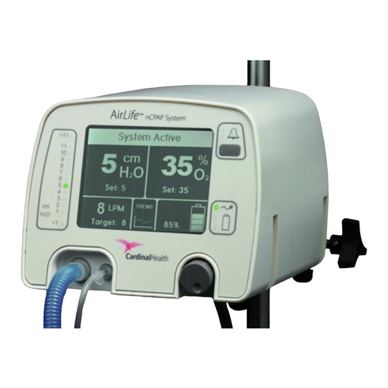
Control Knob (Turn to scroll; Push and release to accept) Trend Selection Flow Display Proximal Pressure Port- Standard 4.5mm Luer compatible ID Patient Circuit Connection- Standard 15mm ID, conical © © © © 2008, Cardinal Health Page 8 of 81... - Page 9 Nationally Recognized Testing Laboratory (NRTL) Classification Figure 3: Underside Features Item Description Water Trap and Air Filter Oxygen Sensor Bleed Port (do not block) Ventilation / Drainage Holes (do not block) (6 places) © © © © 2008, Cardinal Health Page 9 of 81...
- Page 10 ® AirLife nCPAP Driver Service Manual Figure 4: Splash Screen (Displayed only at Startup) Example Screen Figure 5: Icon Legend © © © © 2008, Cardinal Health Page 10 of 81...
-
Page 11: Alarm System
Approximately every three (3) seconds, the system will reinstate flow. If the alarm condition has cleared, the unit will operate © © © © 2008, Cardinal Health Page 11 of 81... -
Page 12: Elevated Pressure Alarm
4.2.7 Low Flow Alarm An audible and visual High Priority Low Flow alarm is preset for flow rates at or below 3 lpm. There is a 10-second delay for this alarm. © © © © 2008, Cardinal Health Page 12 of 81... -
Page 13: Oxygen Concentration Alarms
Power-On Self Test. A Warning Screen will appear indicating which sensor has failed to calibrate and informing the user to remove the device from service. © © © © 2008, Cardinal Health Page 13 of 81... -
Page 14: Warnings And Cautions Summary
WARNING Oxygen vigorously accelerates combustion. To avoid an explosion hazard, do not use any instrument or piece of equipment that may have been exposed to oil or grease contamination. © © © © 2008, Cardinal Health Page 14 of 81... - Page 15 The use of an alarm or monitoring system does not give absolute assurance of warning for every malfunction that may occur in the system. © © © © 2008, Cardinal Health Page 15 of 81...
- Page 16 WARNING Use this product only as directed in the product literature to reduce the possibility of nasal and skin irritation, and necrosis. © © © © 2008, Cardinal Health Page 16 of 81...
- Page 17 Important: Do not spray down the unit with water or cleaning solutions. CAUTION This assembly contains electronic components that are ESD sensitive. ESD control and handling measures should be followed while performing this process. © © © © 2008, Cardinal Health Page 17 of 81...
- Page 18 The driver must have both gases properly connected and within the specified pressure range in order to pass the initial startup sequence. This will enable the driver to perform a valid calibration and ensure accurate delivery. © © © © 2008, Cardinal Health Page 18 of 81...
- Page 19 Note: Do not replace the Top Case until the Power-On Self Test is complete and the Patient Treatment Mode Screen (the main screen) appears. © © © © 2008, Cardinal Health Page 19 of 81...
-
Page 20: Approved Accessories List
37700, 37701, 37702 Reusable Accessories Heated Humidifier Fisher and Paykel MR730, MR850 Driver Stand w/ extension pole & 006995 basket Cardinal Health Stand Power Strip 006996 Stand Tank Holder 006997 © © © © 2008, Cardinal Health Page 20 of 81... -
Page 21: Driver Set-Up, Operation, And Basic Inspection
“Product Specification” section, or use the recommended stand as listed in the approved accessories list. The Driver Attached to a Stand © © © © 2008, Cardinal Health Page 21 of 81... -
Page 22: Inspect Air Filter
The power switch does not disconnect the driver from the main power supply. This can only be accomplished by disconnecting the AC Adapter from either the driver or the AC outlet. © © © © 2008, Cardinal Health Page 22 of 81... -
Page 23: Interaction With Display Settings
“Set” value on the main screen. If the Control Knob is not pressed and released to accept a new value the change will automatically be canceled after ten (10) seconds of inactivity, and the previous setting will remain unchanged. © © © © 2008, Cardinal Health Page 23 of 81... -
Page 24: Standby Mode
(alarms will be delayed for 20 seconds) and blend gases to the previously set FiO value. © © © © 2008, Cardinal Health Page 24 of 81... -
Page 25: Trending
Details about the alarms generated by the driver are listed in sections 4 and 15. Typical Driver Setup © © © © 2008, Cardinal Health Page 25 of 81... -
Page 26: Routine Cleaning & Set-Up
2 years. CAUTION The correct AC Adapter must be used with the driver. Use of an incorrect AC Adapter can damage the internal circuits of the driver. © © © © 2008, Cardinal Health Page 26 of 81... -
Page 27: Unit Inspection And Cleaning
Display indicates the driver is operating on battery power. Indication on the LCD Display includes the Green Power LED ceasing to illuminate, the Plug Icon disappearing and bars appearing in the Battery Icon to indicate the level of available battery life. © © © © 2008, Cardinal Health Page 27 of 81... -
Page 28: Disposal
Disposable accessories include generators, fixation device, prongs, masks, heated wire breathing circuits, and humidification chambers. DO NOT STERILIZE OR REUSE The battery and LCD display must be disposed of according to local regulations. © © © © 2008, Cardinal Health Page 28 of 81... -
Page 29: Driver Maintenance Schedule
WARNING Oxygen vigorously accelerates combustion. To avoid an explosion hazard, do not use any instrument or piece of equipment that may have been exposed to oil or grease contamination. © © © © 2008, Cardinal Health Page 29 of 81... -
Page 30: Recommended Tools And Torque Specifications
Outlet Fitting Assembly Screw Control Knob / Selector Switch Oxygen Bleed Fitting 15 – 20 in-lbs Top Case Mounting Screws Inlet Block Screw 7 in-lbs Manifold Assembly Mounting Screws © © © © 2008, Cardinal Health Page 30 of 81... -
Page 31: Preventive Maintenance- Externally Accessible
To avoid the risk of fire or explosion, use this device in well-ventilated areas away from flammable anesthetics. WARNING When driver is connected to power source, keep cords clear of walkways to avoid possible cord entanglement and strangulation. © © © © 2008, Cardinal Health Page 31 of 81... -
Page 32: Mounting Bracket And Clamp Assembly
(3) #8 mounting screws and lock washers. 4. Inspect the rubber feet. Replace worn feet if necessary. Mounting Bracket and Clamp Assembly, Mounting Bracket and Clamp Assembly, Rear Installation-Standard Orientation Optional Side Orientation © © © © 2008, Cardinal Health Page 32 of 81... -
Page 33: Air Filtration Maintenance
6. Place the bowl over the filter, and using the Filter Bowl Removal Tool, tighten the bowl onto the housing. Visually inspect air filter and filter bowl. Use Delrin tool to remove filter bowl. Unscrew and remove old filter. Place new filter on shaft. © © © © 2008, Cardinal Health Page 33 of 81... -
Page 34: Air And Oxygen Inlet Screen Replacement
If the screens show obvious amounts of debris or discoloration, then consider investigating the cleanliness of the medical grade gases and increasing the frequency of screen replacements. © © © © 2008, Cardinal Health Page 34 of 81... -
Page 35: Oxygen Bleed Flow Measurement
There is one (1) Fast Acting 3.0 Amp 250 V fuse on the rear of the unit. Replace the fuse if blown. Replace the fuse with a Fast Acting 3.0A 250V fuse. © © © © 2008, Cardinal Health Page 35 of 81... -
Page 36: Preventive Maintenance- Internally Accessible
AC outlet. CAUTION This assembly contains electronic components that are ESD sensitive. ESD control and handling measures should be followed while performing this process. © © © © 2008, Cardinal Health Page 36 of 81... -
Page 37: Remove The Top Case From The Bottom Case
Top Case may be difficult to remove due to foam insulation. Be very careful.) Use a 9/64” Allen wrench to remove the socket-head screws. nCPAP driver with Top Case removed. © © © © 2008, Cardinal Health Page 37 of 81... -
Page 38: Replace The Oxygen Sensor Filters
Ensure all joints have remained tight. Filters Luer Lock Ring From To O Manifold Sensor When replacing the Oxygen Sensor Filters, ensure that the components are secured finger tight. © © © © 2008, Cardinal Health Page 38 of 81... -
Page 39: Remove The Front Panel Assembly
Disconnect the Power Cable Assembly from J19 on the Main Board (PCA-01). Disconnect the Main to Bulkhead Cable from the Main Board (PCA-01). Disconnect the Control Knob/Selector Switch from J11 on the Main Board (PCA- 01). © © © © 2008, Cardinal Health Page 39 of 81... - Page 40 Bulkhead to Valves Cable (Step 3). LCD Backlight Power Supply Disconnect the Control Knob/Selector Switch (6). Disconnect the Main to Bulkhead Cable from the Main Board (5) Disconnect the Power Cable Assembly (4) © © © © 2008, Cardinal Health Page 40 of 81...
-
Page 41: Remove The Battery Assembly
Disconnect Valve Drive Cable by squeezing the Bulkhead Connector’s tabs and gently pushing it through the slot in the Divider/Oxygen Sensor Assembly. Gently lift the Battery Assembly from its mount. © © © © 2008, Cardinal Health Page 41 of 81... - Page 42 Reverse procedure to install replacement battery. Always dispose of the battery according to local regulations. Push Bulkhead Connector through Divider Disconnect negative Disconnect positive terminal (2) terminal (4) Remove Power Inlet Panel © © © © 2008, Cardinal Health Page 42 of 81...
-
Page 43: Remove The Manifold Assembly
This assembly contains electronic components that are ESD sensitive. ESD control and handling measures should be followed while performing this process. Gently lift the Manifold Assembly from the Bottom Case. © © © © 2008, Cardinal Health Page 43 of 81... - Page 44 Pinch & push connector through Divider (1)(2) Disconnect luer lock (3) Remove 2 mount screws Disconnect wire from CN22, (6) Disconnect wire from CN21, (5) Disconnect silicone tubing (7) © © © © 2008, Cardinal Health Page 44 of 81...
-
Page 45: Remove The Divider/Oxygen Sensor Assembly
Use a 9/64” Allen wrench to remove the two (2) socket-head screws that secure the Manifold Assembly to the Bottom Case. Tilt Manifold Assembly to access the Remote Sensor Board (PCA-02). © © © © 2008, Cardinal Health Page 45 of 81... - Page 46 (7) Disconnect Remote Remove manifold Pinch and push Board connector (5) mounting screws connector through Divider Disconnect Oxygen Sensor wire to PCA-02, (9) Disconnect silicone tube from case (10) © © © © 2008, Cardinal Health Page 46 of 81...
-
Page 47: Remove The Outlet Fitting Assembly
Use new cable assemblies if they are provided with the replacement Outlet Fitting Assembly, otherwise utilize the two (2) Inlet Pressure Board Cables (red/white/black cables) and the Remote Board to Bulkhead Cable from the replaced assembly. Remove T-10 Torx screw © © © © 2008, Cardinal Health Page 47 of 81... -
Page 48: Remove The Control Knob/Selector Switch
Loosen and remove retaining nut and lock washer with 7/16” open-ended wrench. Push the Selector Switch through the Bottom Case mounting hole. Control Knob, lock washer and Side view of Control nut removed. Knob/Selector Switch © © © © 2008, Cardinal Health Page 48 of 81... -
Page 49: Replace The Main Board (Pca-01)/ Contrast Adjustment
3. Remove four (4) mounting screws using a 5/64” Allen wrench. 4. Tilt the Main Board (PCA-01) up and locate the two (2) ribbon cable connectors. Gently disconnect both cables. © © © © 2008, Cardinal Health Page 49 of 81... - Page 50 6. When installed, the LCD contrast may be adjusted using the contrast adjustment knob on the main PCA board (location noted below). Contrast adjustment Mounting screws (3) 4-pin connector (2) Disconnect ribbon cables (4) © © © © 2008, Cardinal Health Page 50 of 81...
-
Page 51: Replace The Bottom Case
Bottom Case. See section 13 for rebuild instructions. The serial number is located on the rear of the nCPAP driver, affixed to the Bottom Case. © © © © 2008, Cardinal Health Page 51 of 81... -
Page 52: Reassembling The Ncpap Driver
Switch 13.3 Install Battery Assembly Insert the Battery Assembly into the Bottom Case so that the terminals are closest to the interior of the case. Properly installed Battery Assembly. © © © © 2008, Cardinal Health Page 52 of 81... -
Page 53: Install The Outlet Fitting Assembly
Outlet Fitting Assembly, reverse half a turn, and then tighten to a torque of 5 in-lbs using a T-10 Torx driver. Slide the Outlet Fitting Assembly into the Bottom Case at a downward angle. © © © © 2008, Cardinal Health Page 53 of 81... -
Page 54: Install The Divider/Oxygen Sensor Assembly
Position the Divider/Oxygen Sensor Assembly into its mounting slots. Gently insert the Remote Board Bulkhead Cable connector through the corresponding slot in the Divider/Oxygen Sensor Assembly. Attach silicone tube (1) Connect Oxygen Sensor Cable (2) © © © © 2008, Cardinal Health Page 54 of 81... -
Page 55: Install The Manifold Assembly
Bottom Case using a 9/64” Allen wrench. Tighten to a torque of 7 in-lb. 6. Gently insert the Bulkhead to Valves Cable into the corresponding slot in the Divider/Oxygen Sensor Assembly until it locks into place. © © © © 2008, Cardinal Health Page 55 of 81... - Page 56 CN15 to CN21, (2) Press on silicone tube (1) Bulkhead to Valves Connector (6) Connect luer lock to Oxygen Sensor Filters (7) Install 2 mounting screws Torque to 7 in-lbs (5) © © © © 2008, Cardinal Health Page 56 of 81...
-
Page 57: Install Power Cable Assembly
2. Slide the Power Inlet Panel behind the battery, between the ribs in the Bottom Case. Connect the terminals Slide Power Entry Panel Properly Installed panel to the battery (1) behind battery (2) © © © © 2008, Cardinal Health Page 57 of 81... -
Page 58: Install The Front Panel Assembly
J8 (labeled CALIB) 5 and 6 7 and 8 J7 (labeled VENT) 9 and 10 J6 (labeled DELIVERY) 11 and 12 J5 (labeled AIR) J4 (labeled O2) 13 and 14 © © © © 2008, Cardinal Health Page 58 of 81... - Page 59 Verify dip switch configuration Verify cable connections Note: Do not replace the Top Case until the Power-On Self Test is complete and the Patient Treatment Mode Screen (the main screen) appears. © © © © 2008, Cardinal Health Page 59 of 81...
-
Page 60: Install The Top Case
Insert the four (4) #8 screws into the mounting holes and secure using a 9/64” Allen wrench. Torque to 5 in-lbs. Reassembled nCPAP driver with Top Case removed. Align metal panels with slots in Top Case Invert unit, install mounting screws © © © © 2008, Cardinal Health Page 60 of 81... -
Page 61: Charging The Battery After Maintenance
The battery will charge when the unit is powered off and plugged into a wall socket. 13.11 Disposal Recommendations The battery and LCD display must be disposed of according to local regulations. © © © © 2008, Cardinal Health Page 61 of 81... -
Page 62: Comprehensive Performance Test
6. Visually inspect the inlet air filter and filter bowl. If the filter is dirty or wet, it should be replaced. 7. Connect the Device to a clean, dry Air and oxygen source regulated between 41-66 PSI, preferably at a nominal of 50 ± 3 PSI. © © © © 2008, Cardinal Health Page 62 of 81... - Page 63 This is indicated by the “mute” LEDs being illuminated. Exit the grace period by pressing the alarm clear/mute button before proceeding (or allow the unit to time-out after 120 seconds) © © © © 2008, Cardinal Health Page 63 of 81...
- Page 64 27. Record PASS if all values are within the stated accuracy or FAIL if the results fall outside the stated accuracy. If the FiO readings fall outside of the stated range, check the following: © © © © 2008, Cardinal Health Page 64 of 81...
- Page 65 Driver automatically switches to oxygen only. 41. Verify that CPAP pressure is maintained utilizing the oxygen source. Note that the FiO will be 100% and the High FiO alarm will be active. © © © © 2008, Cardinal Health Page 65 of 81...
- Page 66 58. Occlude the prongs and set CPAP to 5 cm H O. Allow valves to stabilize for approximately 60 seconds. 59. Completely occlude the exhaust port momentarily and then release the occlusion. © © © © 2008, Cardinal Health Page 66 of 81...
- Page 67 Note: The expected battery life is 2 years and must be replaced every 2 years. If the battery has been in service for more than 2 years or fails to operate for the stated duration, the battery must be replaced. © © © © 2008, Cardinal Health Page 67 of 81...
-
Page 68: Performance Test Data Sheet
® AirLife nCPAP Driver Service Manual 14.2 Performance Test Data Sheet Airlife nCPAP Driver Performance Test Data Sheet Driver Serial Number: Equipment ID: Test Equipment: ID# / Calibration Due Date Tolerance Test Equipment: ID# / Calibration Due Date Tolerance Manometer... - Page 69 Yes or No PASS FAIL activate 4 hours (inclusive of Run time on Battery PASS FAIL alarm periods) Results of Performance Test: Signature/ Date: Test Disposition PASS or FAIL (Circle One) © © © © 2008, Cardinal Health Page 69 of 81...
-
Page 70: Troubleshooting
• Check supply gases range multiplied by • Red flashing Fault LED • Restart driver to perform oxygen sensor calibration the duration of the • Message Bar says “FiO variance.) Warning” © © © © 2008, Cardinal Health Page 70 of 81... - Page 71 • While alarm is active, the driver provides CPAP and FiO • Oxygen Calibration Error however, the FiO may not be accurate. Warning Screen • Remove patient from device and restart driver © © © © 2008, Cardinal Health Page 71 of 81...
-
Page 72: Warning Screens
41 – 66 psig Warning Screen) is/are above the maximum Faulty or defective inlet Service and/or replace the specified operating range. pressure sensor(s) Manifold Assembly © © © © 2008, Cardinal Health Page 72 of 81... - Page 73 Note displayed watchdog criteria that software fault has been code and re-install the detected by the device may adversely affect latest revision of software the operation of the device © © © © 2008, Cardinal Health Page 73 of 81...
- Page 74 Remove device from Faulty inlet pressure select AIR ONLY mode service and service/repair sensor (FiO will go to 21%) the Manifold Assembly © © © © 2008, Cardinal Health Page 74 of 81...
- Page 75 (air source outside of oxygen blending to the to enter OXYGEN ONLY specification) original FiO setting when mode the Air source has been replenished or the leak is resolved. © © © © 2008, Cardinal Health Page 75 of 81...
-
Page 76: Pneumatic Diagram
® AirLife nCPAP Driver Service Manual PNEUMATIC DIAGRAM © © © © 2008, Cardinal Health Page 76 of 81... - Page 77 Harmonic Applicable establishments and those directly connected to Emissions the public low-voltage power supply network that supplies buildings used for domestic purposes. IEC 61000-3-3 Voltage Fluctuations, Applicable Flicker Emissions © © © © 2008, Cardinal Health Page 77 of 81...
- Page 78 5 sec for 5 sec Note 1—UT is the AC mains voltage prior to application of the test level. Note 2—Performed with an Input Voltage of 120 V AC only. © © © © 2008, Cardinal Health Page 78 of 81...
- Page 79 AirLife nCPAP System Driver. Over the frequency range 150 kHz to 80 MHz, field strengths should be less than 3 V/m. © © © © 2008, Cardinal Health Page 79 of 81...
-
Page 80: Mri Notice
Do not operate this device in an MRI environment or in the vicinity of high-frequency surgical diathermy equipment, defibrillators, or short-wave therapy equipment. Electromagnetic interference could disrupt the operation of the device. © © © © 2008, Cardinal Health Page 80 of 81... -
Page 81: Warranty Information
Cardinal Health's sole obligation under this warranty is limited to the replacement or repair of the product or parts thereof which upon examination are found to contain manufacturing defects or not to conform to the description thereof contained in the relevant manual.
Need help?
Do you have a question about the AirLife nCPAP and is the answer not in the manual?
Questions and answers