Emerson Rosemount 2160 Reference Manual
Wireless level detector
Hide thumbs
Also See for Rosemount 2160:
- Quick start manual (40 pages) ,
- Quick installation manual (21 pages) ,
- Quick start manual (36 pages)

Related Manuals for Emerson Rosemount 2160


Summary of Contents for Emerson Rosemount 2160
- Page 1 Reference Manual 00809-0100-4160, Rev AE May 2022 ™ Rosemount 2160 Wireless Level Detector Vibrating Fork...
- Page 2 Equipment ratings and certifications are no longer valid on any products that have been damaged or modified without the prior written permission of Emerson. Any continued use of product that has been damaged or modified without the written authorization is at the customer’s sole risk and expense.
- Page 3 The products described in this document are NOT designed for nuclear-qualified applications. Using non-nuclear qualified products in applications that require nuclear-qualified hardware or products may cause inaccurate readings. For information on Rosemount nuclear-qualified products, contact your local Emerson Sales Representative. CAUTION Hot surfaces The flange and process seal may be hot at high process temperatures.
-
Page 5: Table Of Contents
6.2 Device display alerts........................53 6.3 Troubleshooting........................57 6.4 Service and troubleshooting tools....................59 6.5 Replace power module......................66 6.6 Opening the lid (cover)......................68 6.7 Service support..........................69 Appendix A Specifications and reference data................71 A.1 General............................71 Rosemount 2160 Wireless Level Detector... - Page 6 Contents Reference Manual May 2022 00809-0100-4160 A.2 Physical specifications....................... 71 A.3 Performance specifications......................72 A.4 Electrical specifications......................73 A.5 Functional specifications......................74 A.6 Environmental specifications.....................75 A.7 Dimensional drawings....................... 77 Appendix B Configuration parameters..................85 B.1 Manual setup..........................85 B.2 Alert setup..........................90 Reference Manual...
-
Page 7: Chapter 1 Introduction
Introduction Using this manual The sections in this manual provide detailed information on installing, operating, and maintaining the Rosemount 2160 Wireless Level Detector - Vibrating Fork. The sections are organized as follows: Level detector overview provides a description of the Rosemount 2160 and its basic principles. - Page 8 Introduction Reference Manual May 2022 00809-0100-4160 Reference Manual...
-
Page 9: Level Detector Overview
Process characteristics Emerson's vibrating fork technology is virtually unaffected by turbulence, foam, solids content, coating products, and liquid properties. The natural frequency (1400 Hz) of the fork avoids interference from plant vibration that may cause false detection. This allows for minimum intrusion into the tank or pipe using a short fork. -
Page 10: Application Examples
Spillage caused by overfilling can be hazardous to people and the environment, resulting in lost product and potentially high clean-up costs. The Rosemount 2160 is an overfill prevention product from Emerson that can be used as one of multiple layers of protection. - Page 11 Rosemount 2160 can be installed in small diameter pipes. Short forks mean minimum intrusion on the wetside and allow for simple, low cost installation at any angle into pipes or tanks. The Rosemount 2160 is ideal for reliable pump control and can be used to protect against pumps running dry.
-
Page 12: Components Of The Level Detector
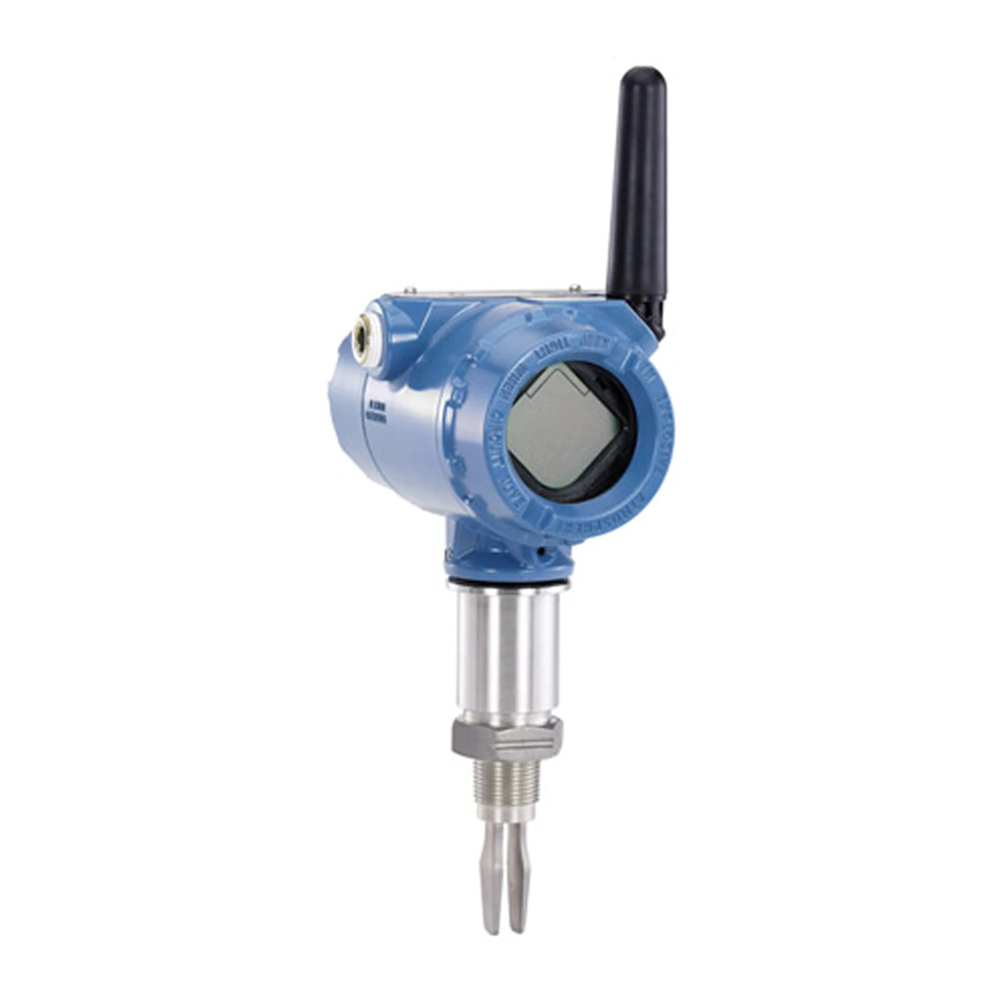
Reference Manual May 2022 00809-0100-4160 Components of the level detector Figure 2-1 shows the components of a Rosemount 2160. Figure 2-1: Rosemount 2160 Features A. Removable cover (no LCD fitted) B. Electronics housing C. LCD display (optional) D. Removable cover (battery compartment) E. - Page 13 2.5.2 Fork design The “fast drip” design allows the liquid to be quickly drawn away from the fork tip, making the Rosemount 2160 quicker and more responsive in high density or viscous liquid applications. Figure 2-2: “Fast drip” forks 2.5.3 Battery powered The device is powered by an integral battery.
-
Page 14: Emerson Wireless
Anti-Jamming, and Key Management ensures that data transmissions are secure and received only by the Gateway. The Rosemount 2160 is a member of the Emerson Wireless portfolio, whose wireless network experience totals billions of operating hours, hundreds of thousands of field devices, and tens of thousands of networks around the world. -
Page 15: Chapter 3 Installation
Ensure the level detector is handled carefully. If the process seal is damaged, gas might escape from the vessel (tank) or pipe. Installation considerations Before installing the level detector, review the safety, environmental, application, and pre- installation sections. Rosemount 2160 Wireless Level Detector... - Page 16 3.2.2 Application considerations The Rosemount 2160 is a wireless HART point level devices for use on open or closed vessels (tanks) and in pipework containing liquid mediums. For most liquids, including coating, aerated liquids and slurries, the function is virtually unaffected by flow, turbulence, bubbles, foam, vibration, solid particles, build-up, or properties of the liquid medium.
- Page 17 Emerson. Foams In almost all cases, the Rosemount 2160 is insensitive to foams (i.e. does not see the foam). However in rare occasions, some very dense foams may be seen as liquid; known examples of this are found in ice-cream and orange juice manufacturing.
- Page 18 Installation Reference Manual May 2022 00809-0100-4160 Switching point The switching point varies with different liquid densities. The switching point (SP) and hysteresis (HY) for water are shown in Figure 3-3. Figure 3-3: Switching Point in Inches (Millimeters) (2.5) (13) (13) Note When mounted vertically, a low density medium has a switching point closer to the process connection.
- Page 19 Figure 3-5: Make No Alterations Allow adequate space outside tank or pipe Mount the Rosemount 2160 so that it is removable and allow easy access to the replaceable battery. Ensure there is also enough room for replacing the battery. Clearances: •...
- Page 20 Ensure a proper seal by installing the electronics housing covers so that metal contacts metal. Always use Emerson's O-rings. Mounting orientation Mount the Rosemount 2160 at any angle that allows the level of the process medium to rise, fall, or flow through the fork gap. Related information...
- Page 21 Extra consideration is needed if the plant vibration is close to the 1400 Hz operating frequency of the fork. Required supports for extended fork Supporting the extended fork avoids long fork length vibration. Figure 3-7: Vertical Installation A. Maximum 3.28 ft. (1.0 m) B. 3.28 ft. (1.0 m) Rosemount 2160 Wireless Level Detector...
-
Page 22: Installation Procedures
Installation Reference Manual May 2022 00809-0100-4160 Figure 3-8: Horizontal Installation A. Maximum 3.28 ft. (1.0 m) B. 3.28 ft. (1.0 m) Installation procedures 3.3.1 Process connection seals Figure 3-9: Process Connection Seals A. PTFE tape B. NPT or BSPT (R) thread C. - Page 23 (Figure 3-11). Figure 3-11: Correct Fork Alignment for Vessel (Tank) Installation A. Tri Clamp process connections have a circular notch B. Threaded process connections have a groove C. Flanged process connections have a circular notch Rosemount 2160 Wireless Level Detector...
- Page 24 Installation Reference Manual May 2022 00809-0100-4160 3.3.3 Mounting the threaded version Threaded vessel (tank) or pipework connection Procedure 1. Seal and protect the threads. Use anti-seize paste or PTFE tape according to site procedures. A gasket may be used as a sealant for BSPP (G) threaded connections. 2.
- Page 25 2. Tighten the bolts and nuts with sufficient torque for the flange and gasket. 3. Seal and protect the threads. Use anti-seize paste or PTFE tape according to site procedures. A gasket may be used as a sealant for BSPP (G) threaded connections. Rosemount 2160 Wireless Level Detector...
- Page 26 Installation Reference Manual May 2022 00809-0100-4160 4. Screw the level detector into the flange thread. Note Tighten using the hexagon nut only. A. Gasket for BSPP (G) threaded connection Reference Manual...
- Page 27 00809-0100-4160 May 2022 3.3.4 Mounting the flanged version Procedure 1. Lower the level detector into the nozzle. A. Gasket (customer supplied) 2. Tighten the bolts and nuts with sufficient torque for the flange and gasket. Rosemount 2160 Wireless Level Detector...
- Page 28 A. Seal (supplied with Tri Clamp) 2. Fit the Tri Clamp. 3.3.6 Install the power module To install the battery that supplies all power to the Rosemount 2160: Procedure 1. Remove the power module cover. 2. Connect the power module.
- Page 29 The antenna should be positioned vertically, either straight up or straight down, and it should be approximately 3 ft. (1 m) from any large structure, building, or conductive surface to allow for clear communication to other devices. Figure 3-15: Antenna Positioned Vertically Rosemount 2160 Wireless Level Detector...
- Page 30 Installation Reference Manual May 2022 00809-0100-4160 3.3.8 Adjust LCD meter orientation If a device display is ordered, it will be shipped attached to the level detector. The display is ordered in the level detector model number, option code M5. Rotate the device display The device display can be rotated in 90-degree increments.
- Page 31 Reference Manual Installation 00809-0100-4160 May 2022 3. Re-tighten the set screw. Note Do not attempt to rotate the housing beyond the thread limit. Figure 3-17: Housing Rotation Torque 30 in-lb (3 Nm) H3/32 in. Rosemount 2160 Wireless Level Detector...
- Page 32 Installation Reference Manual May 2022 00809-0100-4160 Reference Manual...
-
Page 33: Chapter 4 Configuration
WARNING Process leaks could result in death or serious injury. Ensure the level detector is handled carefully. If the process seal is damaged, gas might escape from the vessel (tank) or pipe. Rosemount 2160 Wireless Level Detector... -
Page 34: Configuration Procedure
AMS Wireless Configurator The AMS Wireless Configurator is the recommended software tool for the wireless network devices, and is supplied with the Emerson Wireless Gateway. Configuration can be done by connecting to the wireless network devices either point-to- point using a HART modem as shown in... - Page 35 Procedure Download the latest DD at Emerson.com/DeviceInstallKits. Add the DD to AMS Wireless Configurator Prerequisites The Rosemount 2160 DD is typically installed together with AMS Wireless Configurator. Procedure 1. Close AMS Wireless Configurator. Rosemount 2160 Wireless Level Detector...
- Page 36 Handheld communicator This section describes how to prepare the handheld communicator to communicate with a Rosemount 2160. The handheld communicator can be used to configure the device with a point-to-point connection. Connect the leads on the handheld communicator to the communication terminals of the device.
-
Page 37: Join Device To Wireless Network
2. Enable Active Advertising on the Gateway to ensure that new devices join the network faster. Related information Install the power module Startup screen sequence The following screens will be displayed in sequence when the power module is first connected to the Rosemount 2160. Rosemount 2160 Wireless Level Detector... - Page 38 Configuration Reference Manual May 2022 00809-0100-4160 Table 4-1: Startup Screen Sequence Screen Sequence Description 1. All segments ON Used to visually determine if there are any bad segments on the device display. 2. Device identification Identification string used to determine the device type. 3.
- Page 39 Active Alerts screen in AMS Wireless Configurator or the handheld communicator. Some active alerts will be displayed on the LCD display as part of the diagnostic button screen sequence. Rosemount 2160 Wireless Level Detector...
- Page 40 Configuration Reference Manual May 2022 00809-0100-4160 4.4.2 Connect to device Procedure ® 1. Connect a handheld communicator or a HART modem to the communication terminals as shown in Figure 4-4. Figure 4-4: Connect to Device A. Communication terminals B. Handheld communicator C.
- Page 41 In order to communicate with the Wireless Gateway, and ultimately the host system, the Rosemount 2160 must be configured to communicate on the wireless network. This step is the wireless equivalent of connecting wires from a device to the host system.
- Page 42 • Using the handheld communicator If the Rosemount 2160 was configured with the Network ID and Join Key, and sufficient time has passed, the device should be connected to the network. It usually takes a few minutes for the device to join the network.
- Page 43 Network Active Search The device is actively searching for a network. n e t w k a - s r c h Rosemount 2160 Wireless Level Detector...
- Page 44 Configuration Reference Manual May 2022 00809-0100-4160 Table 4-2: Network Connection Status Screens (continued) Screen Status Description Network Passive Search The device is passively searching for a network. n e t w k p - s r c h Network Sleep The device couldn’t find the network and is in deep sleep mode to preserve battery power.
- Page 45 Figure 4-6: Network Connection Status Images Verify by Gateway Procedure 1. From the Emerson Wireless Gateway home page, navigate to the Devices page. This page shows whether the device has joined the network and if it is communicating properly. 2. Locate the device in question and verify all status indicators are good (green).
-
Page 46: Configure Device Using Guided Setup
Configuration Reference Manual May 2022 00809-0100-4160 Note In order to communicate with a handheld communicator, the device must be powered by the power module. Procedure 1. Connect the handheld communicator. 2. Select Service Tools → Communications. 3. Select Join Status. Configure device using guided setup The options available in the Basic Setup wizard include all items required for basic operation. -
Page 47: Chapter 5 Operation
The device display can be used to present different variables and a diagnostic screen sequence. 5.1.1 Variable screens The Rosemount 2160 can display the following variables: Figure 5-1: LCD Display Variables PV - Fork state SV - Fork frequency TV - Electronic temperature... -
Page 48: View Diagnostic Screens
Operation Reference Manual May 2022 00809-0100-4160 View diagnostic screens The diagnostic button screen sequence on the device display can be used to obtain detailed diagnostic information. Procedure 1. Unscrew the device display cover. 2. Press and hold the DIAG button until the first diagnostic button screen appears on the device display. - Page 49 5. Supply voltage Used to indicate the voltage of the battery. S u p l y 7. 2 1 v o l t s Related information Device display alerts Rosemount 2160 Wireless Level Detector...
-
Page 50: View Measurement Data
Operation Reference Manual May 2022 00809-0100-4160 View measurement data Current measurement data of the primary variables are presented on the Overview screen. To view all current measurement values: Procedure Select Service Tools → Variables. 5.3.1 Interpret measurement status A “Good” or “Bad” status next to a value is an indication of the reliability or integrity of the data being received, not an indication of whether or not the value is within the configured upper or lower ranges. - Page 51 At least one Maintenance Alert is Click the Investigate button to active (and no Failed alerts). open a window with Active Alerts together with recommended actions. Advisory At least one Advisory Alert is active (and no Failed or Maintenance Alerts). Rosemount 2160 Wireless Level Detector...
- Page 52 Operation Reference Manual May 2022 00809-0100-4160 Reference Manual...
-
Page 53: Service And Troubleshooting
Ensure the level detector is handled carefully. If the process seal is damaged, gas might escape from the vessel (tank) or pipe. Device display alerts The following active alert screens will show the device diagnostics depending on the state of the device. Rosemount 2160 Wireless Level Detector... - Page 54 Service and troubleshooting Reference Manual May 2022 00809-0100-4160 If the device display shows ALERT PRESNT but none of the following screens appear, then go to the Active Alerts screen in AMS Wireless Configurator or the handheld communicator for further information. For detailed information of the failure source and recommended actions, go to the Active Alerts screen in AMS Wireless Configurator or the handheld communicator.
- Page 55 Radio failure Screen Cause The wireless radio has detected a failure or stopped communicating. Recommended actions 1. Reset the device. 2. If the condition persists, contact your local Emerson representative. Related information Perform a device reset Rosemount 2160 Wireless Level Detector...
- Page 56 Service and troubleshooting Reference Manual May 2022 00809-0100-4160 6.2.5 Configuration failure Screen Cause Configuration of the device is invalid such that critical operation of the device may be affected. Recommended actions Check the extended configuration status to identify which configuration item(s) need to be corrected.
-
Page 57: Troubleshooting
Rotate the device display Display mode 6.3.2 Does not switch output state Possible cause There is no power. Recommended actions Check the power module is installed correctly. Try another power module. Possible cause Fork is damaged. Rosemount 2160 Wireless Level Detector... - Page 58 Service and troubleshooting Reference Manual May 2022 00809-0100-4160 Recommended actions Replace the device. Possible cause Thick encrustation on the forks. Recommended actions Clean the fork with care. 6.3.3 Incorrect switching of output state Recommended actions Check the configuration of frequency bands. Related information Calibration frequencies and switch points 6.3.4...
-
Page 59: Service And Troubleshooting Tools
Select Service Tools → Communications → Join Status. Obtain network join details Obtain detailed information about the network join, and configure how the device attempts to join the network. Procedure Select Service Tools → Communications. Rosemount 2160 Wireless Level Detector... - Page 60 Service and troubleshooting Reference Manual May 2022 00809-0100-4160 Network join details Table 6-1: Network Join Details Functions Term Description Join Mode This mode configures how the device attempts to join the network. Settable options are: • Don't Attempt to Join •...
- Page 61 Too Wet (Fault) 0.0 (Dry) Fault Zero 0.0 (Dry) Sensor Fault Delay delays the update of Sensor State when the operation mode is Enhanced. PV is not changed. PV is automatically changed to 0.0 (Dry process condition). Rosemount 2160 Wireless Level Detector...
- Page 62 Table 6-5: Calibration Frequencies and Switch Points Term Description Dry fork frequency This is the frequency recorded when the Rosemount 2160 was calibrated in dry conditions. Typically it is in the range 1.2 to 1.5 KHz. Dry to too dry Above this upper limit, a measured frequency is considered to be a fault by being outside of the normal dry fork range.
- Page 63 Reset/Preset Wet Count command. Calibration Count The Rosemount 2160 is calibrated under reference conditions at the factory. In special circumstances, it may be re-calibrated in the field and this will increment the calibration count.
- Page 64 Service and troubleshooting Reference Manual May 2022 00809-0100-4160 If the difference is greater than Allowable Change In Dry Fork Frequency, the re-calibration is rejected. Check the fork for damage, corrosion, or coating, and clean it if necessary before re-trying. When the calibration is successful, Dry Fork Frequency is set to the new dry frequency. Related information Allowable change in fork frequency Start the dry fork calibration...
- Page 65 2. Select Install New Power Module and follow the on-screen instructions. 6.4.8 Perform a device reset The Device Reset function re-starts electronics of the Rosemount 2160 without having to cycle the power. It preserves the user-configuration. Procedure 1. Select Service Tools → Maintenance, → Reset/Restore 2.
-
Page 66: Replace Power Module
A simulation is canceled by exiting the screen. It can also be cleared by the power cycling or using the Device Reset command. Replace power module Prerequisites Only use an Emerson approved power module designed for use with the Rosemount 2160. The power modules are only compatible with their respective covers. Procedure 1. Remove the cover. - Page 67 A. Keep cover tight Postrequisites Run the install new power module setup. Related information Emerson Wireless Black SmartPower Solutions Product Data Sheet Emerson Wireless Blue SmartPower Solutions Product Data Sheet Run the install new power module setup Rosemount 2160 Wireless Level Detector...
-
Page 68: Opening The Lid (Cover)
Service and troubleshooting Reference Manual May 2022 00809-0100-4160 6.5.1 Handling considerations The power modules with the wireless unit contains primary lithium/thionyl chloride batteries. Under normal conditions, the battery materials are self-contained and are not reactive as long as the batteries and the battery pack integrity are maintained. Care should be taken to prevent thermal, electrical or mechanical damage. -
Page 69: Service Support
Returned products must include a copy of the required Safety Data Sheet (SDS) for each substance. Emerson representatives will explain the additional information and procedures necessary to return goods exposed to hazardous substances. - Page 70 Service and troubleshooting Reference Manual May 2022 00809-0100-4160 Reference Manual...
-
Page 71: Appendix A Specifications And Reference Data
Emerson is not in a position to evaluate or guarantee the compatibility of the process fluid or other process parameters with the product, options, configuration, or materials of construction selected. -
Page 72: Performance Specifications
4.1 in. (105 mm) 118.1 in. (3000 mm) Maximum extended length of fork with hand-polished option is 39.4 in. (1000 mm). Performance specifications A.3.1 Electromagnetic Compatibility (EMC) All versions of the Rosemount 2160 meet all relevant requirements of EN 61326. Reference Manual... -
Page 73: Electrical Specifications
Reference conditions are 70 °F (21 °C), and routing data for three additional network devices. Continuous exposure to ambient temperature limits -40 °F or 185 °F (-40 °C or 85 °C) may reduce specified power module life by 20 percent. Rosemount 2160 Wireless Level Detector... -
Page 74: Functional Specifications
Specifications and reference data Reference Manual May 2022 00809-0100-4160 A.4.3 Handheld communicator connections Clips are permanently fixed to the terminal block. Functional specifications A.5.1 Outputs ® IEC 62591 (WirelessHART ) 2.4 GHz DSSS A.5.2 Radio frequency power output from antenna Maximum of 10 mW (10 dBm) EIRP A.5.3 Wireless update rate... -
Page 75: Environmental Specifications
EN1092-1 PN 100 100 barg ASTM stainless steel. At 100 °F (38 °C), the pressure rating decreases with an increasing process temperature. At 122 °F (50 °C), the pressure rating decreases with an increasing process temperature. Rosemount 2160 Wireless Level Detector... - Page 76 Specifications and reference data Reference Manual May 2022 00809-0100-4160 A.6.2 Maximum and minimum operating temperatures Figure A-2 for the maximum and minimum operating temperatures. Figure A-2: Operating Temperatures 176 (80) 176 (80) 122 (50) 149 (65) 2160***S 2160***E 32 (0) 32 (0) -40 (-40) -40 (-40)
-
Page 77: Dimensional Drawings
8.4 (212) 6.1 (154) 7.7 (196) (121) 90° 4.2 (107) 9.2 (233) A. LCD display (option M5) B. No LCD display C. Black Power Module cover (option WK1) D. Blue Power Module cover (option WK2) Rosemount 2160 Wireless Level Detector... - Page 78 Specifications and reference data Reference Manual May 2022 00809-0100-4160 Figure A-4: Threaded Process Connections (Standard Fork Length) (121) 2160***S 2160***E (172) 14.5 (369) (69) (44) A. 1.6 (40) A/F hexagon B. ¾- or 1-in. thread C. 0.5 (13) switchpoint (when mounted vertically) D.
- Page 79 F. Customer specified fork length (see Table A-1) Dimensions are in inches (millimeters). Table A-3: Tube Diameters Tube material Size Tube diameter in inches (mm) ¾-in. 316/316L 0.9 (22.9) 1-in. 1.125 (28.6) ¾-in. Alloy C/C-276 0.84 (21.4) 1-in. 1.050 (26.7) Rosemount 2160 Wireless Level Detector...
- Page 80 Specifications and reference data Reference Manual May 2022 00809-0100-4160 Figure A-6: Flanged Process Connections (Standard Fork Length) (121) 2160***S 2160***E (177) 13.8 (351) (102) (44) A. Ø0.9 (23) for 1-in. flange; Ø1.14 (29) for 1½-in. or larger flange B. 0.5 (13) switchpoint (when mounted vertically) C.
- Page 81 A. Ø0.9 (23) for 1-in. flange; Ø1.14 (29) for 1½-in. or larger flange B. 0.5 (13) switchpoint (when mounted vertically) C. 0.5 (13) switchpoint (when mounted horizontally) D. Customer specified fork length (see Table A-1) Dimensions are in inches (millimeters). Rosemount 2160 Wireless Level Detector...
- Page 82 Specifications and reference data Reference Manual May 2022 00809-0100-4160 Figure A-8: Tri Clamp Process Connections (Standard Fork Length) (121) 2160***S 2160***E (179) 14.7 (374) Ø0.9 (Ø23) (64) (44) A. ½-in. (38) or 2-in. (52) Tri Clamp B. 0.5 (13) switchpoint (when mounted vertically) C.
- Page 83 A. ½-in. (38) or 2-in. (52) Tri Clamp B. 0.5 (13) switchpoint (when mounted vertically) C. 0.5 (13) switchpoint (when mounted horizontally) D. Customer specified fork length (see Table A-1) Dimensions are in inches (millimeters). Rosemount 2160 Wireless Level Detector...
- Page 84 Specifications and reference data Reference Manual May 2022 00809-0100-4160 Reference Manual...
-
Page 85: Appendix B Configuration Parameters
Default update rate This defines how often the broadcast message is sent to the gateway. Faster update rates have an impact on the total communications traffic on the network, and power module life. Rosemount 2160 Wireless Level Detector... - Page 86 If, for example, there are waves in a tank, then the Rosemount 2160 may intermittently detect a change in process conditions. The sensor output delay ensures that the fork of the level detector is dry or wet for a period before switching.
- Page 87 The default setting is "60 ms". It can be set to a time in the range 20 to 1000 ms and is adjustable in 20 ms steps. Alternatively, the setting "AUTO" is for the Rosemount 2160 to automatically calculate a delay.
- Page 88 Configuration parameters Reference Manual May 2022 00809-0100-4160 • Supply Voltage variable If more than one variable is selected, the display will toggle between the values of those variables. B.1.4 Data logging The level detector can store a series of 12 data collection (sample) points for a chosen device variable.
- Page 89 Configures the device to take periodic measurements to conserve battery life, or to take continuous measurements. Note Always On mode is only recommended for devices connected to line power. Power source Optimizes the device to make use of the power source to which it is attached. Rosemount 2160 Wireless Level Detector...
-
Page 90: Alert Setup
Reference Manual May 2022 00809-0100-4160 Alert setup B.2.1 Process alerts Process alerts allow the Rosemount 2160 to indicate when a pre-set data point is exceeded. Alerts can be set for the following device variables: • Output State • Sensor Frequency •... - Page 91 E. Assigned value F. Alert "ON" Limit Alert set point (in same units as the variable). Deadband Hysteresis data point (in same units as the variable) for transition from deadband zone to new alert state. Rosemount 2160 Wireless Level Detector...
- Page 92 2022 Emerson. All rights reserved. Emerson Terms and Conditions of Sale are available upon request. The Emerson logo is a trademark and service mark of Emerson Electric Co. Rosemount is a mark of one of the Emerson family of companies. All other marks are the property...
Need help?
Do you have a question about the Rosemount 2160 and is the answer not in the manual?
Questions and answers