Emerson Rosemount 2140 Reference Manual
Level detectors, vibrating fork
Hide thumbs
Also See for Rosemount 2140:
- Reference manual (144 pages) ,
- Quick start manual (24 pages) ,
- Quick start manual (16 pages)

Related Manuals for Emerson Rosemount 2140


Summary of Contents for Emerson Rosemount 2140
- Page 1 Reference Manual 00809-0100-4140, Rev BA March 2022 ™ Rosemount 2140 and 2140:SIS Level Detectors Vibrating Fork...
- Page 2 The weight of a level detector with a heavy flange and extended fork length may exceed 37 lb. (18 kg). A risk assessment is required before carrying, lifting, and installing the level detector. For installations in hazardous locations, the level detector must be installed according to the Rosemount 2140 and 2140:SIS Level Detectors Product Certifications document.
- Page 3 Equipment ratings and certifications are no longer valid on any products that have been damaged or modified without the prior written permission of Emerson. Any continued use of product that has been damaged or modified without the written authorization is at the customer’s sole risk and expense.
-
Page 5: Table Of Contents
5.10 Security........................... 45 Chapter 6 Operation........................ 49 6.1 LCD display screen messages..................... 49 6.2 Set up the LCD display....................... 50 6.3 View measurement data......................50 6.4 Check device status........................51 6.5 Partial proof testing........................53 Rosemount 2140 and 2140:SIS Level Detectors... - Page 6 Contents Reference Manual March 2022 00809-0100-4140 Chapter 7 Service and troubleshooting..................57 7.1 Safety messages........................57 7.2 Diagnostic messages......................... 58 7.3 Troubleshooting the 4-20 mA/HART Output................68 7.4 Service and troubleshooting tools....................69 7.5 Opening the lid (cover)......................76 7.6 Service support..........................76 Appendix A Specifications and reference data................
-
Page 7: Chapter 1 Introduction
The sections in this manual provide detailed information on installing, operating, and maintaining the Rosemount 2140 and 2140:SIS Level Detectors. The sections are organized as follows: Level detector overview provides a description of the Rosemount 2140 and , and their basic principles. Mechanical installation contains mechanical installation instructions. -
Page 8: Namur Ne 53 Revision
Reference Manual March 2022 00809-0100-4140 NAMUR NE 53 revision The Rosemount 2140 meets the NAMUR recommendation NE 53. Table 1-1 provides the information necessary to ensure you have the correct device driver for your device. Table 1-1: Identification and Compatibility According to NAMUR NE 53... -
Page 9: Level Detector Overview
2.2.1 Liquid-to-sediment detection The Rosemount 2140 version of the level detector features settings to detect liquid-to- sediment interface, and this works on other solids sediment types (e.g. salts). Liquids as well as wet sediments are detected. All versions of the level detector have a Media Learn function to fine-tune the switching point even if the media characteristics are unknown. -
Page 10: Application Examples
Extended length versions require supports at regular spaced intervals. Application examples Applications for the Rosemount 2140 version of the level detector include overfill prevention (Figure 2-1), high and low level alarms, pump protection, and separation... -
Page 11: Components Of The Level Detector
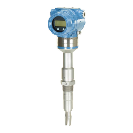
Reference Manual Level detector overview 00809-0100-4140 March 2022 Components of the level detector Figure 2-3 shows the components of a Rosemount 2140. Figure 2-3: Rosemount 2140 Features A. Terminal compartment B. Electronics housing C. LOI display (optional) D. ‘Fast drip’ forks E. - Page 12 2.5.2 Fork design The “fast drip” design allows the liquid to be quickly drawn away from the fork tip, making the Rosemount 2140 quicker and more responsive in high density or viscous liquid applications. Figure 2-4: “Fast drip” forks Reference Manual...
-
Page 13: Chapter 3 Mechanical Installation
37 lb. (18 kg). A risk assessment is required before carrying, lifting, and installing the level detector. For installations in hazardous locations, the level detector must be installed according to the Rosemount 2140 and 2140:SIS Level Detectors Product Certifications document. -
Page 14: Installation Considerations
Before installing the level detector, review the safety, environmental, application, and pre- installation sections. 3.2.1 Environmental considerations The Rosemount 2140 is weatherproof and protected against the ingress of dust, but must be protected from flooding. Avoid installing the level detector near heat sources. Reference Manual... - Page 15 Avoid process medium build-up on the forks Avoid situations where a drying and coating process medium may create an excessive build-up or implement preventative maintenance programs to ensure the build-up is not enough to impair performance (see Figure 3-2). Rosemount 2140 and 2140:SIS Level Detectors...
- Page 16 Up to 1000 cP (centiPoise) when operating in Enhanced mode. Foams In almost all cases, the Rosemount 2140 is insensitive to foams (i.e. does not see the foam). However in rare occasions, some very dense foams may be seen as liquid; known examples of this are found in ice-cream and orange juice manufacturing.
- Page 17 37 lb. (18 kg). A risk assessment is required to be done before carrying, lifting, and installing the level detector. Use both hands to carry the extended length and high temperature versions, and do not hold a level detector by the forks (see Figure 3-4). Rosemount 2140 and 2140:SIS Level Detectors...
- Page 18 Mechanical installation Reference Manual March 2022 00809-0100-4140 Figure 3-4: Handling Make no alterations to the level detector Never make any alterations to the mechanical or electrical features of the level detector (see Figure 3-5). Figure 3-5: Make No Alterations Allow adequate space outside tank or pipe Mount a level detector so that it is removable and allow both covers to be removed.
- Page 19 Ensure a proper seal by installing the electronics housing covers so that metal contacts metal. Always use Emerson's O-rings. Mounting orientation Mount the Rosemount 2140 at any angle that allows the level of the process medium to rise, fall, or flow through the fork gap. Related information...
- Page 20 Mechanical installation Reference Manual March 2022 00809-0100-4140 Other recommendations • Avoid: — Installing near to liquid entering the tank at the filling-point. — Heavy splashing on the forks. Increasing the sensor output delay reduces accidental detection caused by splashing. • Always ensure: —...
- Page 21 Reference Manual Mechanical installation 00809-0100-4140 March 2022 Figure 3-8: Horizontal Installation A. Maximum 3.28 ft. (1.0 m) B. 3.28 ft. (1.0 m) Rosemount 2140 and 2140:SIS Level Detectors...
-
Page 22: Installation Procedures
Mechanical installation Reference Manual March 2022 00809-0100-4140 Installation procedures 3.3.1 Process connection seals Figure 3-9: Process Connection Seals A. PTFE tape B. NPT or BSPT (R) thread C. Gasket D. BSPP (G) thread E. Tri Clamp F. The Tri Clamp seal is supplied in an accessory kit Reference Manual... - Page 23 The fork is correctly aligned by positioning the groove or notch as indicated (Figure 3-11). Figure 3-11: Correct Fork Alignment for Pipe Installation A. Tri Clamp process connections have a circular notch B. Threaded process connections have a groove Rosemount 2140 and 2140:SIS Level Detectors...
- Page 24 Mechanical installation Reference Manual March 2022 00809-0100-4140 3.3.3 Mounting the threaded version Threaded vessel (tank) or pipework connection Procedure 1. Seal and protect the threads. Use anti-seize paste or PTFE tape according to site procedures. A gasket may be used as a sealant for BSPP (G) threaded connections. 2.
- Page 25 2. Tighten the bolts and nuts with sufficient torque for the flange and gasket. 3. Seal and protect the threads. Use anti-seize paste or PTFE tape according to site procedures. A gasket may be used as a sealant for BSPP (G) threaded connections. Rosemount 2140 and 2140:SIS Level Detectors...
- Page 26 Mechanical installation Reference Manual March 2022 00809-0100-4140 4. Screw the level detector into the flange thread. Note Tighten using the hexagon nut only. A. Gasket for BSPP (G) threaded connection 3.3.4 Mounting the flanged version Procedure 1. Lower the level detector into the nozzle. A.
- Page 27 2. Tighten the bolts and nuts with sufficient torque for the flange and gasket. 3.3.5 Mounting the Tri Clamp version Procedure 1. Lower the level detector into the flange face. A. Seal (supplied with Tri Clamp) Rosemount 2140 and 2140:SIS Level Detectors...
-
Page 28: Adjust Display Orientation (Optional)
Mechanical installation Reference Manual March 2022 00809-0100-4140 2. Fit the Tri Clamp. Adjust display orientation (optional) To improve field access to wiring or to better view the optional LCD display: Procedure 1. Loosen the set screw until the level detector housing can rotate smoothly. Do not unscrew all the way. -
Page 29: Chapter 4 Electrical Installation
4.1.6 Load limitations ® For HART communications, a minimum load resistance of 250 Ω is required. The maximum loop resistance is determined by the voltage level of the external power supply (see Figure 4-1). Rosemount 2140 and 2140:SIS Level Detectors... - Page 30 Electrical installation Reference Manual March 2022 00809-0100-4140 Figure 4-1: Load Limitations 1400 1392 1200 1000 10.5 16.3 42.4 Maximum loop resistance = 43.5 × (external power supply voltage - 10.5) A. Loop resistance in Ohms (Ω) B. External power supply voltage (Vdc) 4.1.7 Wiring diagram ®...
- Page 31 The level detector can withstand electrical transients of the energy level usually encountered in static discharges or induced switching transients. However, high-energy transients, such as those induced in wiring from nearby lightning strikes, can damage the level detector. Rosemount 2140 and 2140:SIS Level Detectors...
-
Page 32: Connect Wiring And Power Up
Electrical installation Reference Manual March 2022 00809-0100-4140 A transient protection terminal block can be ordered as an installed option (code T1). The lightning bolt symbol in identifies the transient protection terminal block. Note The transient protection terminal block does not provide transient protection unless the housing is properly grounded. - Page 33 3. Remove the plastic plugs. 4. Pull the cable through the cable gland/conduit. Identification of thread size and type: ½-14 NPT M20 x 1.5 5. Connect the cable wires. Torque 7 in-lb (0.8 Nm) 6. Ensure proper grounding. Rosemount 2140 and 2140:SIS Level Detectors...
- Page 34 Electrical installation Reference Manual March 2022 00809-0100-4140 7. Tighten the cable gland. Apply PTFE tape or other sealant to the threads. Note Make sure to arrange the wiring with a drip loop. 8. Plug and seal the unused conduit connection to avoid moisture and dust accumulation inside the housing.
- Page 35 Turn the cover jam screw counterclockwise until it contacts the cover. M2.5 b) Turn the jam screw an extra ½ turn counterclockwise to secure the cover. c) Verify that the cover cannot be removed. 11. Connect the power supply. Rosemount 2140 and 2140:SIS Level Detectors...
- Page 36 Electrical installation Reference Manual March 2022 00809-0100-4140 Reference Manual...
-
Page 37: Chapter 5 Configuration
37 lb. (18 kg). A risk assessment is required before carrying, lifting, and installing the level detector. For installations in hazardous locations, the level detector must be installed according to the Rosemount 2140 and 2140:SIS Level Detectors Product Certifications document. -
Page 38: Configuration Tools
Configuration Reference Manual March 2022 00809-0100-4140 WARNING Electrical shock could cause death or serious injury. Avoid contact with the leads and terminals. High voltage that may be present on leads can cause electrical shock. Ensure the power to the level detector is off, and the lines to any other external power source are disconnected or not powered while wiring the level detector. -
Page 39: Local Operator Interface (Loi)
LOI menu use multiple screens to complete their configuration. Any data entered is saved on a screen-by-screen basis, and the LOI indicates this by flashing “SAVED” on the LCD display each time. Rosemount 2140 and 2140:SIS Level Detectors... -
Page 40: Confirm Correct Device Driver
ENTER Confirm correct device driver Procedure 1. Verify that the correct FDI/DD/DTM Package is loaded on your systems to ensure proper communication. 2. Download the latest FDI/DD/DTM Package at Emerson.com/DeviceInstallKits FieldCommGroup.org. Related information NAMUR NE 53 revision ® Confirm HART... -
Page 41: Configure Device Using Guided Setup
Verify configuration using a handheld communicator Table 5-2 lists the configuration parameters to be reviewed before using the level detector live in a process. From the HOME screen of the handheld communicator, enter the fast key sequences as listed. Rosemount 2140 and 2140:SIS Level Detectors... - Page 42 Configuration Reference Manual March 2022 00809-0100-4140 Table 5-2: Verifying Configuration (Fast Key Sequences) Parameter Fast key sequence HART 7 HART 5 1, 8, 1, 2 1, 8, 1, 1 Model 1, 8, 1, 3 1, 8, 1, 3 Primary Variable 3, 2, 1, 1 3, 2, 1, 1 Sensor Operating Mode...
-
Page 43: Multidrop Communication
Multidropping refers to the connection of several devices to a single communications transmission line. Communication between the host device and another device takes place digitally with the analog output of the level detector deactivated. Figure 5-3 shows a typical multidrop network. Rosemount 2140 and 2140:SIS Level Detectors... -
Page 44: Hart Burst Mode
Configuration Reference Manual March 2022 00809-0100-4140 Figure 5-3: Typical Multidrop Network A. HART modem B. Power supply Multidrop installation requires consideration of the update rate necessary from each device, the combination of different device types, and the length of the transmission line. Communication with devices can be accomplished with HART modems and a host implementing the HART protocol. -
Page 45: Security
Security switch The security switch is set to the Locked position to prevent configuration changes using ® the optional Local Operator Interface (LOI) or HART interfaces. Figure 5-4 shows the security switch inside the housing. Rosemount 2140 and 2140:SIS Level Detectors... - Page 46 Configuration Reference Manual March 2022 00809-0100-4140 Figure 5-4: Alarm Level and Security Switches With LOI display Without LOI display A. Alarm level switch B. Security switch 5.10.2 Set the position of the security switch When the security switch is set to the locked position ( ) , all configuration requests made using HART, LOI, or local configuration buttons are rejected.
- Page 47 Set the LOI password using the LOI Procedure 1. Press any LOI configuration button to activate the menu. 2. Scroll down ( ) and then select EXTENDED MENU ( ) Rosemount 2140 and 2140:SIS Level Detectors...
- Page 48 Configuration Reference Manual March 2022 00809-0100-4140 3. Scroll down ( ) and then select PASSWORD ( ) . 4. Enable the LOI password protection. 5. Enter a 4-digit number as the password. 6. Exit the menu system by either waiting one minute for the EXIT MENU? prompt, or scrolling down menus to find and select BACK TO MENU and EXIT MENU.
-
Page 49: Chapter 6 Operation
DEG F / DEG C The live temperature at the electronics. Temperature Supply Voltage The live voltage at the terminals. Analog Output The live analog output current. Default parameter displayed. Not available for Rosemount 2140:SIS. Rosemount 2140 and 2140:SIS Level Detectors... -
Page 50: Set Up The Lcd Display
Operation Reference Manual March 2022 00809-0100-4140 Set up the LCD display It is possible to specify the variables to be presented on the optional LCD display. Procedure 1. Select Configure → Manual Setup → Display. 2. Select the desired variables to be displayed on the LCD display. 6.2.1 Set up the LCD display using the LOI It is possible to specify the variables to be presented on the optional LCD display. -
Page 51: Check Device Status
2. If status is anything other than Good, select the button in the device status image to open a window with Active Alerts. Active Alerts can also be obtained via Service Tools → Alerts. Related information Diagnostic messages Rosemount 2140 and 2140:SIS Level Detectors... - Page 52 Operation Reference Manual March 2022 00809-0100-4140 6.4.1 Device status images Table 6-2: Presentation of Device Status Images as per NAMUR NE 107 – AMS Device Manager Device status image Category Description Action Good No active alert. Failure At least one Failure alert is Click the Troubleshoot button active.
-
Page 53: Partial Proof Testing
For Safety Instrumented System (SIS) applications, the Rosemount 2140:SIS must be tested at regular intervals. This is to detect any failures not automatically detected by the device self-test at start-up and the continuous fork sensor diagnostics when operating in Enhanced mode. - Page 54 Operation Reference Manual March 2022 00809-0100-4140 6.5.2 Start the local partial proof test By default, the partial proof testing sequence is not started at every power-up. It can be started by an operator using the Local Operator Interface (LOI). Procedure In the menu system, select TEST →...
- Page 55 The analog output current is overridden to the High Alarm level (as configured). Note Setting a value of “0 s” (zero seconds) results in the analog output not being exercised during the proof-test. Only a diagnostic check of the device is performed in this case. Rosemount 2140 and 2140:SIS Level Detectors...
- Page 56 Operation Reference Manual March 2022 00809-0100-4140 Reference Manual...
-
Page 57: Service And Troubleshooting
37 lb. (18 kg). A risk assessment is required before carrying, lifting, and installing the level detector. For installations in hazardous locations, the level detector must be installed according to the Rosemount 2140 and 2140:SIS Level Detectors Product Certifications document. -
Page 58: Diagnostic Messages
Service and troubleshooting Reference Manual March 2022 00809-0100-4140 WARNING Electrical shock could cause death or serious injury. Avoid contact with the leads and terminals. High voltage that may be present on leads can cause electrical shock. Ensure the power to the level detector is off, and the lines to any other external power source are disconnected or not powered while wiring the level detector. - Page 59 BOARD Cause A failure has been detected in the electronics circuit board. Recommended actions 1. Reset the device. 2. If the condition persists, contact your local Emerson representative. Related information Reset the device Memory error Category Failure – Fix Now...
- Page 60 A fault has been detected in the vibrating fork sensor. This may be due to serious corrosion, coating, physical damage or an internal fault. Recommended actions 1. Inspect the fork sensor for damage and clean if necessary. 2. If the condition persists, contact your local Emerson representative. 7.2.2 Function check Analog output fixed...
- Page 61 The device is in simulation mode and may not be reporting actual information. Recommended actions 1. Verify that simulation is no longer required. 2. Disable simulation mode in Service Tools. 3. Perform a device reset. Related information Simulation mode Reset the device Rosemount 2140 and 2140:SIS Level Detectors...
- Page 62 The instrument electronics temperature is outside the operating range of the device. Recommended actions 1. Check the ambient temperature conditions are within limits. 2. If the condition persists, contact your local Emerson representative. Related information Maximum and minimum operating temperatures...
- Page 63 The sensor frequency is beyond the operating range of the fork sensor. Recommended actions 1. Check the condition of the fork sensor. 2. Reset the device. 3. If the condition persists, contact your local Emerson representative. Related information Reset the device Rosemount 2140 and 2140:SIS Level Detectors...
- Page 64 Service and troubleshooting Reference Manual March 2022 00809-0100-4140 Output state alert Category Out of Specification – Fix Soon LOI screen OUTPUT ALERT Cause The output state has gone beyond the configured trip points. Recommended actions Verify that the configuration of the trip points is as intended and expected. Related information Alert setup Sensor state alert...
- Page 65 LOI screen TEMPERAT ALERT Cause The electronics temperature has gone beyond the configured trip points. Recommended actions Verify that the configuration of the trip points is as intended and expected. Related information Alert setup Rosemount 2140 and 2140:SIS Level Detectors...
- Page 66 A fault has been detected in the non-volatile memory of this device. Recommended actions 1. Reconfirm all configuration items of the device. 2. Reset the device. 3. If the condition persists, contact your local Emerson representative. Related information Reset the device Reference Manual...
- Page 67 One of the keys on the LOI is detected as stuck in the active position. Recommended actions 1. Check the keys for obstructions. 2. Reset the device. 3. If the condition persists, contact your local Emerson representative. Sensor frequency unstable Category Maintenance Required...
-
Page 68: Troubleshooting The 4-20 Ma/Hart Output
Service and troubleshooting Reference Manual March 2022 00809-0100-4140 Troubleshooting the 4-20 mA/HART Output 7.3.1 Device milliamp reading is zero Recommended actions 1. Verify power is applied to signal terminals. 2. Verify power supply voltage is adequate at signal terminals. 3. Check power wires for reversed polarity. 4. -
Page 69: Service And Troubleshooting Tools
Sensor Fault Delay does not delay the update of Sensor State when the operation mode is Normal. Note If the operation mode is Normal, Sensor State cannot indicate Too Dry, Too Wet, or Zero, and the Sensor Status always indicates a Valid state. Rosemount 2140 and 2140:SIS Level Detectors... - Page 70 Service and troubleshooting Reference Manual March 2022 00809-0100-4140 Table 7-2: Enhanced Mode, Fault = Wet Sensor status Sensor state Current output PV (output state) operating mode Valid Wet on Off (0.0) Valid Dry on On (1.0) Fault Too Dry Wet on On (1.0) Valid Wet on...
- Page 71 Table 7-4: Calibration Frequencies and Switch Points Term Description Dry fork frequency This is the frequency recorded when the Rosemount 2140 was calibrated in dry conditions. The frequency is typically 1260 to 1500 Hz. The default dry fork frequency is established at the point of manufacture.
- Page 72 Service and troubleshooting Reference Manual March 2022 00809-0100-4140 7.4.3 Reset to factory settings The function resets the user-configuration to the ex-factory settings. Procedure 1. Select Service Tools → Maintenance → Reset/Restore. 2. Select Factory Reset and follow the on-screen instructions. 7.4.4 Dry fork calibration This command starts the on-site calibration of the fork sensor in dry process conditions.
- Page 73 Use this function to calibrate the analog output by comparing the actual output current with the nominal 4 mA and 20 mA currents. Prerequisites Calibration is done at factory and the analog output does not normally need to be recalibrated. Rosemount 2140 and 2140:SIS Level Detectors...
- Page 74 Service and troubleshooting Reference Manual March 2022 00809-0100-4140 A reference meter (ammeter) is a required for measuring the actual output current at 4 mA and 20 mA. If a resistor is added to the loop, ensure that the power supply is sufficient to power the level detector to a 20 mA output with that additional loop resistance.
- Page 75 Terminal Voltage The Terminal Voltage device variable can be temporarily overridden with an entered voltage value. Note Simulations are canceled by exiting a screen. They also be cleared by a power re-cycle or device reset. Rosemount 2140 and 2140:SIS Level Detectors...
-
Page 76: Opening The Lid (Cover)
• No rain can enter into the housing. Service support To expedite the return process outside of the United States, contact the nearest Emerson representative. Within the United States, call the Emerson Instrument and Valve Response Center using the 1-800-654-RSMT (7768) toll-free number. This center, available 24 hours a day, will assist you with any needed information or materials. - Page 77 Returned products must include a copy of the required Safety Data Sheet (SDS) for each substance. Emerson Instrument and Valve Response Center representatives will explain the additional information and procedures necessary to return goods exposed to hazardous substances.
- Page 78 Service and troubleshooting Reference Manual March 2022 00809-0100-4140 Reference Manual...
-
Page 79: Appendix A Specifications And Reference Data
Applications Point level detection in liquid process mediums, including coating liquids, aerated liquids, and slurries. Suitable for horizontal and vertical installation. Functional safety The Rosemount 2140:SIS is IEC 61508 certified to: • Type B low-demand device • SIL 2 @ HFT = 0 •... -
Page 80: Electrical Specifications
Digital process variable is superimposed on 4–20 mA signal, available to any host that conforms to HART protocol. Table A-1: Current Output Availability Current Output operating types Rosemount 2140 Rosemount 2140:SIS (profile option code A) (profile option code F) 8/16 mA HART switched output... -
Page 81: Environmental Specifications
The final rating depends on the process-wetted connection. Threaded connection Figure A-1. Tri Clamp connection 435 psig (30 barg) Flanged connection The maximum operating pressure is the lower of the process pressure (Figure A-1) and flange pressure rating (see Table A-2). Rosemount 2140 and 2140:SIS Level Detectors... - Page 82 32 (0) 32 (0) -40 (-40) -40 (-40) (-40) (-70) (80) (260) (80) (180) A. Ambient Temperature, °F (°C) B. Process Temperature, °F (°C) See the Rosemount 2140 Product Certifications document for operating temperature limits required by approvals. Reference Manual...
-
Page 83: Physical Specifications
Emerson is not in a position to evaluate or guarantee the compatibility of the process fluid or other process parameters with the product, options, configuration or materials of construction selected. -
Page 84: Dimensional Drawings
59.1 in. (1500 mm) and 39.4 in. (1000 mm) respectively. Dimensional drawings Refer to the Type 1 Drawings on the Rosemount 2140 web page for dimensions of the O- ring seal (BSPP) versions. Reference Manual... - Page 85 G. Conduit/cable entry M20 x 1.5 or ½-in. ANPT H. Housing rotation set screw. Do not unscrew all the way. Rotating the housing, without this screw in place, can damage the internal wiring Dimensions are in inches (millimeters). Rosemount 2140 and 2140:SIS Level Detectors...
- Page 86 Specifications and reference data Reference Manual March 2022 00809-0100-4140 Figure A-4: ¾- and 1-in. Threaded Process Connection (Mid Temperature Range) 9.1 (235) 9.9 (253) 2.7 (69) 1.7 (44) 1.7 (44) A. Standard length fork B. Extended length fork C. 1.6 (40) A/F hexagon D.
- Page 87 F. 0.5 (13) switching point when mounted vertically G. 0.5 (13) switching point when mounted horizontally H. Ø1.14 (29) for 1-in. thread; Ø0.9 (23) for ¾-in. thread I. Customer specified fork length (see Table A-3) Dimensions are in inches (millimeters). Rosemount 2140 and 2140:SIS Level Detectors...
- Page 88 Specifications and reference data Reference Manual March 2022 00809-0100-4140 Figure A-6: 2-in. Threaded Process Connection (Mid Temperature Range) 9.1 (232) (232) 10.1 (257) 5.2 (131) 1.7 (44) 1.7 (44) Ø1.14 (29) Ø1.14 (29) A. Standard length fork B. Extended length fork C.
- Page 89 E. Ø0.9 (23) for up to 1-in. flange; Ø0.95 (24) for up to 1-in. coated flange; Ø1.14(29) for 1½-in. or larger flange F. Customer specified fork length (see Table A-3) Dimensions are in inches (millimeters). Rosemount 2140 and 2140:SIS Level Detectors...
- Page 90 Specifications and reference data Reference Manual March 2022 00809-0100-4140 Figure A-8: Flanged Process Connection (High Temperature Range) 16.1 (410) 16.1 (410) 4 (102) 1.7 (44) 1.7 (44) A. Standard length fork B. Extended length fork C. Thermal tube D. 0.5 (13) switching point when mounted vertically E.
- Page 91 C. 1½- or 2-in. Tri Clamp D. 0.5 (13) switching point when mounted vertically E. 0.5 (13) switching point when mounted horizontally F. Customer specified fork length (see Table A-3) Dimensions are in inches (millimeters). Rosemount 2140 and 2140:SIS Level Detectors...
- Page 92 Specifications and reference data Reference Manual March 2022 00809-0100-4140 Figure A-10: Tri Clamp Process Connection (High Temperature Range) 17.0 (433) 17.3 (440) Ø1.6 (39) 2.5 (64) 1.7 (44) 1.7 (44) Ø1.14 (29) A. Standard length fork B. Extended length fork C.
-
Page 93: Appendix B Configuration Parameters
0.5 – 0.9 SG 500 to 900 kg/m 0.8 – 1.3 SG 800 to 1300 kg/m 1.2 – 3.0 SG 1200 to 3000 kg/m Only available when the Sensor Operating Mode is set to Normal. Rosemount 2140 and 2140:SIS Level Detectors... - Page 94 Configuration parameters Reference Manual March 2022 00809-0100-4140 Additional options are available when the Sensor Operating Mode is set to Normal: • Low compacted sediment • Medium compacted sediment • High compacted sediment • Extreme compacted sediment Calculated switching points for a process media The measured frequency of the fork, when immersed in process medium, can be affected by liquid density variations.
- Page 95 Allowable change in dry fork frequency When the level detector is re-calibrated in the field, a comparison is made between the new dry fork frequency and original factory-set Dry Fork Frequency value. If the difference Rosemount 2140 and 2140:SIS Level Detectors...
- Page 96 The default setting is 5 seconds. It can be set to a value in the range 0 to 3600 seconds. Note When the Rosemount 2140 is operating in Normal mode, a fork sensor fault is not detected and Sensor State continues to indicate a valid state.
- Page 97 PV dynamic variable. The limits are used for scaling gauges in a Host system and for validating the Analog Output range points. Table B-5: Sensor Limits for Device Variables Device Variable PV Lower Limit PV Upper Limit Output State Sensor State Sensor Frequency 250.0 Hz 1800.0 Hz Rosemount 2140 and 2140:SIS Level Detectors...
- Page 98 Configuration parameters Reference Manual March 2022 00809-0100-4140 Table B-5: Sensor Limits for Device Variables (continued) Device Variable PV Lower Limit PV Upper Limit Electronics Temperature –40 °C 85 °C Terminal Voltage 10.5 V 42.4 V Scaled Variable Defined by sensor frequency limits and scaling data. By default, the Output State is mapped to the PV.
- Page 99 Scaled output 1 The first scaled variable value which will be associated with the first frequency value. Frequency input 2 The second frequency value which will be associated with the second scaled variable value. Rosemount 2140 and 2140:SIS Level Detectors...
- Page 100 Configuration parameters Reference Manual March 2022 00809-0100-4140 Scaled output 2 The second scaled variable value which will be associated with second first frequency value. Linear offset The user entered offset which is added or subtracted from the calculated scaled variable output.
- Page 101 By default, this security is not enabled. The configuration button lock disables all local button functionality. LOI password By default, this security is not enabled. A Local Operator Interface password can be set to disable the review and modification of configuration data. Related information Security Rosemount 2140 and 2140:SIS Level Detectors...
- Page 102 Configuration parameters Reference Manual March 2022 00809-0100-4140 B.1.8 Frequency profiling There are two frequency profiling functions supported: • Minimum deviation • Maximum deviation Both functions monitor the fork sensor frequency changes. Figure B-3: Frequency Profile Definition 1800 • Fork frequency (Hz) •...
- Page 103 The date field can be used for any purpose, for example to save the date of the last configuration change. Descriptor The 16-character descriptor field can be used for any purpose. Message The 32-character message field can be used for any purpose, such as providing details of the last configuration change. Rosemount 2140 and 2140:SIS Level Detectors...
-
Page 104: Alert Setup
Configuration parameters Reference Manual March 2022 00809-0100-4140 Alert setup B.2.1 Process alerts Process alerts allow the level detector to indicate when a pre-set data point is exceeded. Alerts can be set for the following device variables: • Output State • Sensor State •... - Page 105 It is not possible to predict and detect all types of electrical failures on the 4-20 mA analog output. Therefore, Emerson cannot absolutely warrant or guarantee that Power Advisory will accurately detect failures under all circumstances.
- Page 106 Severe changes in the electrical loop may inhibit HART communication or the ability to reach alarm values. Therefore, Emerson cannot absolutely warrant or guarantee that the correct failure alarm level (high or low) can be read by the host system at the time of annunciation.
- Page 107 This requires the user to acknowledge and clear the alert or alarm. The four Power Advisory diagnostic actions are: • None • Alert latched • Alarm unlatched • Alert unlatched Rosemount 2140 and 2140:SIS Level Detectors...
- Page 108 Configuration parameters Reference Manual March 2022 00809-0100-4140 Reference Manual...
-
Page 109: Appendix C Local Operator Interface (Loi) Menu Trees
(*2) Only visible when the Primary Variable (“PV”) is mapped to the Sensor Frequency or Scaled Variable variables. (*3) Alarm level and saturation level depend on the Alarm Level switch setting and the ordered Alarm Level option code. (*4) Not available for Rosemount 2140:SIS. Rosemount 2140 and 2140:SIS Level Detectors... - Page 110 SIMULATE SIMULATE OUTPUT HART REV SIMULATE STATE HART7 REV SIMULATE FREQ HART5 REV (*1) SIMULATE SCALED BACK TO MENU SIMULATE TEMP EXIT MENU SIMULATE VOLTAG END SIMUL BACK TO MENU EXIT MENU (*1) Not available for Rosemount 2140:SIS. Reference Manual...
-
Page 111: Appendix D Signal Processing
K. Sensor state simulation L. Sensor state simulation enabled M. Output state simulation N. Output state simulation enabled O. Scaled variable calculation P. Scaled variable simulation Q. Scaled variable R. PV selection S. Rosemount 2140 version only Rosemount 2140 and 2140:SIS Level Detectors... - Page 112 2022 Emerson. All rights reserved. Emerson Terms and Conditions of Sale are available upon request. The Emerson logo is a trademark and service mark of Emerson Electric Co. Rosemount is a mark of one of the Emerson family of companies. All other marks are the property...
Need help?
Do you have a question about the Rosemount 2140 and is the answer not in the manual?
Questions and answers