Emerson Rosemount 2160 Quick Start Manual
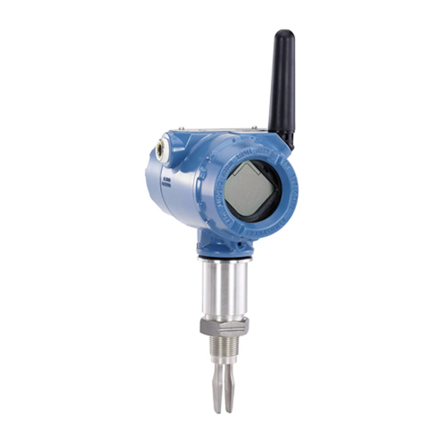
Wireless level detector
Hide thumbs
Also See for Rosemount 2160:
- Reference manual (92 pages) ,
- Quick start manual (36 pages) ,
- Quick installation manual (21 pages)

Related Manuals for Emerson Rosemount 2160


Summary of Contents for Emerson Rosemount 2160
- Page 1 Quick Start Guide 00825-0100-4160, Rev CC February 2021 ™ Rosemount 2160 Wireless Level Detector Vibrating Fork...
- Page 2 Quick Start Guide February 2021 Contents About this guide...........................3 Installation........................... 6 Configuration..........................16 Product certifications......................... 30 Rosemount 2160 Wireless Level Detector...
-
Page 3: About This Guide
February 2021 Quick Start Guide About this guide This Quick Start Guide provides basic guidelines for the Rosemount 2160. Refer to the Rosemount 2160 Reference Manual for more instructions. The manual and this guide are also available electronically at Emerson.com/ Rosemount. - Page 4 In explosion-proof/flameproof and non-incendive/type n installations, do not remove the housing covers when power is applied to the level detector. Both housing covers must be fully engaged to meet flameproof/explosion- proof requirements. Rosemount 2160 Wireless Level Detector...
- Page 5 February 2021 Quick Start Guide WARNING Process leaks could result in death or serious injury. Ensure the level detector is handled carefully. If the process seal is damaged, gas might escape from the vessel (tank) or pipe. WARNING Physical access Unauthorized personnel may potentially cause significant damage to and/or misconfiguration of end users’...
-
Page 6: Installation
(Figure 2-2). Figure 2-2: Correct Fork Alignment for Vessel (Tank) Installation A. Tri Clamp process connections have a circular notch B. Threaded process connections have a groove C. Flanged process connections have a circular notch Rosemount 2160 Wireless Level Detector... - Page 7 February 2021 Quick Start Guide Mounting the threaded version 2.3.1 Threaded vessel (tank) or pipework connection Procedure 1. Seal and protect the threads. Use anti-seize paste or PTFE tape according to site procedures. A gasket may be used as a sealant for BSPP (G) threaded connections. 2.
- Page 8 2. Tighten the bolts and nuts with sufficient torque for the flange and gasket. 3. Seal and protect the threads. Use anti-seize paste or PTFE tape according to site procedures. A gasket may be used as a sealant for BSPP (G) threaded connections. Rosemount 2160 Wireless Level Detector...
- Page 9 February 2021 Quick Start Guide 4. Screw the level detector into the flange thread. Note Tighten using the hexagon nut only. A. Gasket for BSPP (G) threaded connection Quick Start Guide...
- Page 10 Quick Start Guide February 2021 Mounting the flanged version Procedure 1. Lower the level detector into the nozzle. A. Gasket (customer supplied) Rosemount 2160 Wireless Level Detector...
- Page 11 February 2021 Quick Start Guide 2. Tighten the bolts and nuts with sufficient torque for the flange and gasket. Quick Start Guide...
- Page 12 Quick Start Guide February 2021 Mounting the Tri Clamp version Procedure 1. Lower the level detector into the flange face. A. Seal (supplied with Tri Clamp) 2. Fit the Tri Clamp. Rosemount 2160 Wireless Level Detector...
- Page 13 February 2021 Quick Start Guide Install the power module To install the battery that supplies all power to the Rosemount 2160: Procedure 1. Remove the power module cover. 2. Connect the power module. 3. Replace the power module cover and tighten to safety specification (metal-to-metal).
- Page 14 3. Rotate the display to the desired orientation, and snap the display into place. Note If the device display four-pin connector is inadvertently removed from the interface board, carefully re-insert the connector before snapping the device display back into place. Rosemount 2160 Wireless Level Detector...
- Page 15 February 2021 Quick Start Guide Adjust housing orientation The housing can be rotated for optimal viewing of the optional LCD display and to get the best antenna position. Procedure 1. Loosen the set screw until the level detector housing can rotate smoothly.
-
Page 16: Configuration
3.2.1 AMS Wireless Configurator The AMS Wireless Configurator is the recommended software tool for the wireless network devices, and is supplied with the Emerson Wireless Gateway. Configuration can be done by connecting to the wireless network devices either point-to-point using a HART modem as shown in... - Page 17 The Device Descriptor (DD) is a configuration tool that is developed to assist the user through the configuration. Procedure Download the latest DD at Emerson.com/DeviceInstallKits. Add the DD to AMS Wireless Configurator Prerequisites The Rosemount 2160 DD is typically installed together with AMS Wireless Configurator. Quick Start Guide...
- Page 18 4. In the drop-down list select Wireless Network and then select Install. 5. Follow the on-screen instructions. Need help? In the Network Configuration application, select the Help button for more information on how to complete this operation. Rosemount 2160 Wireless Level Detector...
- Page 19 Handheld communicator This section describes how to prepare the handheld communicator to communicate with a Rosemount 2160. The handheld communicator can be used to configure the device with a point-to-point connection. Connect the leads on the handheld communicator to the communication terminals of the device.
- Page 20 Quick Start Guide February 2021 Startup screen sequence The following screens will be displayed in sequence when the power module is first connected to the Rosemount 2160. Table 3-1: Startup Screen Sequence Screen Sequence Description 1. All segments ON Used to visually determine...
- Page 21 February 2021 Quick Start Guide Table 3-1: Startup Screen Sequence (continued) Screen Sequence Description 5. Secondary Variable (PV) Fork (switch) frequency. - Fork frequency 6. Tertiary Variable (TV) - Temperature value of Electronic temperature device electronics. 7. Quaternary Variable Voltage reading of the (QV) - Supply voltage power module.
- Page 22 Turn on the handheld communicator and connect to the device. 3.3.3 Configure update rate The Update Rate is the frequency at which a new measurement is transmitted over the wireless network. The default update rate is 1 minute. Rosemount 2160 Wireless Level Detector...
- Page 23 Obtain network ID and join key In order to communicate with the Wireless Gateway, and ultimately the host system, the Rosemount 2160 must be configured to communicate on the wireless network. This step is the wireless equivalent of connecting wires from a device to the host system.
- Page 24 • Using the handheld communicator If the Rosemount 2160 was configured with the Network ID and Join Key, and sufficient time has passed, the device should be connected to the network. It usually takes a few minutes for the device to join the network.
- Page 25 February 2021 Quick Start Guide Network connection status screens When joining the wireless network, there is a sequence of status changes until the network is finally joined. Table 3-2 presents the different network connection status screens. Table 3-2: Network Connection Status Screens Screen Status Description...
- Page 26 AMS Wireless Configurator window as illustrated in Figure 3-5. Figure 3-5: AMS Wireless Configurator Screen Figure 3-6 presents the different network connection status images that are shown in the AMS Wireless Configurator Overview screen. Rosemount 2160 Wireless Level Detector...
- Page 27 February 2021 Quick Start Guide Figure 3-6: Network Connection Status Images Verify by Gateway Procedure 1. To use the Wireless Gateway's integrated web interface, navigate to the Explorer → Status page as shown in Figure 3-7. This page shows whether the device has joined the network and if it is communicating properly.
- Page 28 Start guided basic setup using AMS Wireless Configurator The options available in the Basic Setup wizard include all items required for basic operation. Procedure 1. Start AMS Wireless Configurator. 2. Select View → Device Connection View. Rosemount 2160 Wireless Level Detector...
- Page 29 February 2021 Quick Start Guide 3. Double-click the device icon. 4. Select Configure → Guided Setup. 5. Select Basic Setup and follow the on-screen instructions. 3.4.2 Start guided basic setup using a handheld communicator The options available in the Basic Setup wizard include all items required for basic operation.
-
Page 30: Product Certifications
All wireless devices require certification to ensure that they adhere to regulations regarding the use of the RF spectrum. Nearly every country requires this type of product certification. Emerson is working with governmental agencies around the world to supply fully compliant products and remove the risk of violating country directives or laws governing wireless device usage. - Page 31 February 2021 Quick Start Guide U.S.A. 4.7.1 I5 Intrinsic Safety (IS), Non-Incendive (NI), Dust Ignition-proof (DIP) Certificate FM17US0357X Standards FM Class 3600:2011; FM Class 3610:2010; FM Class 3611:2004; FM 3810:2005; ANSI/ISA 61010-1:2012; ® ANSI/ISA 60079-11:2013; ANSI/NEMA 250:1991; ANSI/IEC 60529:2004 Markings IS: Class I/II/III, Division 1, Groups A, B, C, D, E, F, and G IS: Class I, Zone 0, AEx ia IIC T4 (Ta = -58 °F to +158 °F / -50 °C to +70 °C)
- Page 32 2. The Rosemount 2160 enclosure is made of aluminum alloy and given a protective epoxy coating; however, care should be taken to protect it from impact or abrasion if located in a Zone 0.
- Page 33 2. The Rosemount 2160 enclosure is made of aluminum alloy and given a protective epoxy coating; however, care should be taken to protect it from impact or abrasion if located in a Zone 0.
- Page 34 2160X**E***********I7****** (“*” indicates options in construction, function, and materials). 1. The Rosemount 2160 may be used in a hazardous area with flammable gases and vapors with apparatus groups IIC, IIB and IIA, and temperature classes T1 to T5. The temperature class of the installation will be determined from the highest process or ambient temperature.
- Page 35 To avoid electrostatic charge build-up, it must not be rubbed or cleaned with solvents or a dry cloth. c. The Rosemount 2160 enclosure is made of aluminum alloy and given a protective epoxy coating; however, care should be taken to protect it from impact or abrasion if located in an area where Equipment Protection Level Ga is required (Zone 0 locations).
- Page 36 Minimum ambient air temperature (T ) = –58 °F (–50 °C) Minimum process temperature (T ) = –94 °F (–70 °C) d. Materials: Refer to the Rosemount 2160 Product Data Sheet. e. Year of manufacture: Printed on the product label.
- Page 37 February 2021 Quick Start Guide 4.17 EU Declaration of Conformity Figure 4-1: EU Declaration of Conformity Quick Start Guide...
- Page 38 Quick Start Guide February 2021 Rosemount 2160 Wireless Level Detector...
- Page 39 February 2021 Quick Start Guide Quick Start Guide...
- Page 40 For more information: www.emerson.com © 2021 Emerson. All rights reserved. Emerson Terms and Conditions of Sale are available upon request. The Emerson logo is a trademark and service mark of Emerson Electric Co. Rosemount is a mark of one of the Emerson family of companies.
Need help?
Do you have a question about the Rosemount 2160 and is the answer not in the manual?
Questions and answers