WisyCom MCR42 User Manual
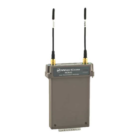
Single-dual true diversity camera receiver
Hide thumbs
Also See for MCR42:
- Quick start manual (5 pages) ,
- Manual (4 pages) ,
- User manual (45 pages)

Related Manuals for WisyCom MCR42


Summary of Contents for WisyCom MCR42
- Page 1 MCR41/MCR42 User Manual Single-Dual True Diversity Camera Receiver SN: ________________ rev.14 (rif. FW 3.21) Date: 24 November 2017...
-
Page 2: Brief Description
MCR41/42 is a high performance microphone receiver suitable for broadcast and high professional applications. Thanks to Wisycom movable filter technology, MCR42 is able to work in a bandwidth up to 230 MHz, still keeping an exceptional selectivity and intermodulation immunity. -
Page 3: Safety Instruction
WARNING: when operating thru battery pack always replace ALL BATTERIES. DO NOT operate the device with some new and some old batteries. When MCR42 is setup to “automatically turn on”, DO CHANGE ALL OF USED BATTERIES after automatic low batteries shutdown. -
Page 4: Main Features
High audio performances and flexibility with analog or digital processors High reliability and durability One of the milestones in the design of the MCR42 is high reliability: most of the circuitry of the receiver is independent one from each other. - Page 5 The high speed audio algorithms implemented in assembler into the MCR42 maintains the audio delay at about 1.3 milliseconds, making it ideally for live events and to keep audio delay as short as possible. The DSP unit also filters and demodulates the data carrier and communicates all the parameters and informations to the supervisor micro controller.
-
Page 6: New Display
A & B SMA antenna Connector: MCR42 is supplied with a couple of antenna tuned on 400 MHz bandwidth suitable to be used with MCR42-N, MCR42-M, MCR42-L, MCR42-H version. RGB Leds: Each of the 2 receivers has a dedicated set of LED’s to give a clear indication of its status. - Page 7 During menu navigation push this button to exit from current menu (escape function). E “Arrow up/sync” BUTTON Push and keep this button to start a synchronization with a Wisycom transmitter (follow instructions on display). Before starting synchronization IRDA must be enabled on Wisycom transmitter.
-
Page 8: Display Menu
MCR41/MCR42 User Manual Display menu Using navigation buttons it is possible to quick & easy navigate through the MCR42 menu: - SEL/Exit to enter or exit a level - Arrow up/down to circle on the same level - To save the modified parameters press and hold the SEL /MENU button ( ) until appears the message "SAVED!". - Page 9 MCR41/MCR42 User Manual...
-
Page 10: Status Menu
MCR41/MCR42 User Manual STATUS MENU Group Frequency Channel Status Screen Modulation bar Squelch Level RF bar (from -42 to 0 dB) (8 steps of 10dBµV, TX battery Peak deviation ≥ 56KHz from 10 to 80 dBµV) Level Quick Menu From FW version 3.0, pushing “Arrow down/scan” button or “Arrow up/sync”... - Page 11 Pushing SEL button it’s possible to change freq/GR/CH. From FW 3.0 and above, it’s possible to assign a name and an Expander to a channel using the Wisycom MCR4x Manager v.1.0.1 or above (to understand how to do it, read...
- Page 12 - AES max lev: -30÷0 dBFS - COM max lev: -18÷12 dBu (only with BPA42-PTT) MAIN MENU Infrared: By activating the infrared, you can connect the MCR42 to other devices (such as a UPK300) Preset: The preset menu has the following two submenus: ...
- Page 13 In the info menu the following information are displayed: Info description example Power: Supply voltage measured 12.0Volt MCR42 dual rx / MCR41 MCR42 dual rx Model: Serial: The serial number composed by 1 letter+7 numbers S3536539 Frequency range according to the MCR band:...
-
Page 14: Advanced Menu
Power on (only for MCR42, not MCR41) Allow to enable both the receivers: Only receiver 1 (Rx1), only receiver (Rx2) or (Rx1 + Rx2). Edit RX (MCR42 has the same menu for RX1 and RX2) Selecting this sub-menu most of RX1 or RX2 setups are configurable. - Page 15 NB: The compander of the receiver must be the same as the transmitter MCR42 core is a power digital audio processor that, besides an unbeatable audio quality and flexibility, can emulate most expanders systems on the market. On this menu you can setup the audio expanding chipset emulation.
- Page 16 MCR41/MCR42 User Manual Edit RX: Tone Squelch MCR42 is able to detect a digital tone squelch generated by a Wisycom transmitters (ex. MTH400/MTH300/MTP40/ MTP30). Tone squelch ON: when the tone squelch is enabled the audio is muted unless the correct carrier is detected. Tone...
- Page 17 Edit RX: Audio Out In Audio Out it’s possible to set the maximum audio output. For MCR42 with Hardware version ≥ 21, the max audio level of the RX1/RX2 output can be set from -30dBu to -10 dBu (in the first selection appears “MIC max lev”) and from -8dBu to +12 dBu (in the first selection appears “LINE max lev”)
-
Page 18: Line Mode
SYNC and SCAN buttons), making easier to pick up the best one. NOTE: As per Wisycom standard, group 00 and group 01 or 09 are special; respectively the “center frequency” (474,482/... MHz) and the intergap frequency (i.e. 470/478/486/... MHz). A scan on... - Page 19 MCR41/MCR42 User Manual Headphones (only for BPA42-HPN) Cycle through menu’s with up/down arrow to get your desired configuration then confirm with SEL. Volume: It is possible to set the desired output level from Max (+6 dB) to min (-24 dB) in 1 dB step.
- Page 20 After the selection of the desiderate receiver that you want to synchronize (RX1 or RX2 for MCR42), pull the infrared sensors of the 2 devices and wait for it to synchronize. At the end of this operation the 2 devices will...
-
Page 21: Error List
MCR41/MCR42 User Manual RROR LIST When an error occurs, the receiver shows a message on the display and for some error types increases the errors counter in the info menu inserts the error type and code on the error list in the info menu... -
Page 22: Troubleshooting
RX2 copy2 invalid CRC-16 check of RX2 data (copy 2) automatically replace the detects error. corrupt copy2 with copy1) - send to repair at Wisycom PLL unlocked Error during frequency tuning Repair Centre During the MTK952 initialization phase, - send to repair at Wisycom... -
Page 23: Accessories And Parts
MCR41/MCR42 User Manual ACCESSORIES AND PARTS MCR42 has 4 main audio sources: Audio Line 1&2 AES3 (audio 1&2, 48kHz 24bit) PTT (push to talk) COM1 & COM2 Headphone (left/right) which can be bring on TOP FEED and/or on BASE (slot-in or stand alone panel). - Page 24 TOP FEED OPTIONS Top feed can bring on top on a mini-XLR 5M connector two balanced audio outputs. MCR42-Exx can then be in factory configure to connect on top (LINE1/2 or COM 1/2) the audio source you need. Line 1 & 2 to XLR MCR42-EL2: Audio Line 1 &...
- Page 25 NOTE: With this option, it’s not possible to use the AES3 output in the standalone socket and it’s not guaranteed the correct functionality of the AES3 Option indicated in the label output in the top feed. BPA42-K "Stand-alone" KIT for MCR42 BPA42PTT + 2 x CAM 50-2 + CDC34...
- Page 26 MCR41/MCR42 User Manual BPA42BAG: Stand alone socket LINE2 LINE1 Line1 (pigtail) • Analogue audio output electronically balanced, adjustable in a one dB step between -30/-18dBu (depending on the Hardware version) and +6 dBu (nominal) and MAX +12 dBu (peak deviation) •...
-
Page 27: Slot In Sockets
MCR41/MCR42 User Manual SLOT IN SOCKETS To transform MCR42 in slot-in compatible for a specific camera you need to use a kit with a rear panel and a flange. Under the item BASE of the submenu INFO you can see the type of rear panel "Slot-in"... - Page 28 MCR41/MCR42 User Manual UFLA42-IK-OP Ikegami flange compatible with new PSC Six Pack STAND ALONE HARNESS CABLE- DB25 (to MCR42,Ikegami/Panasonic slot-in compatible)- 2 CAU42-IKSS XLR-3M (line output) + USB (power and management with SLK42-IKSS/2) STAND ALONE HARNESS CABLE- DB25 (to MCR41, Ikegami/Panasonic slot-in compatible)- 1...
- Page 29 MCR41/MCR42 User Manual AF cable (50 cm), mini XLR-5F / 1 XLR-3M connectors CAM50-42 Line 2 feed XL3-M (TO BE USED FOR AES3 CAMERA INPUT) External power feeding cable, hirose/raw wires (50 CDC34 AF cable (40cm), mini XLR-3F / XLR-3M (line output...
- Page 30 NOTE: BPA42-PTT (or -HPN) must be installed FLA42 FLA42-SX Screw-disassemble back-panel Screw-disassemble back-panel For camera-hardware mounting (not drilled) For camera-hardware mounting (for Sony cameras) BCL42 VAP42 Belt clip factory mounted on FLA42 Carrying case for MCR41/42 Eng Systems. MCRMNT CAMERA SHOE MOUNT for MCR41/MCR42...
-
Page 31: Stand Alone Mounting
MCR41/MCR42 User Manual Stand Alone Mounting MCR42: Line1 is configured to AES3 output (audio 1 & 2) and PTT - CAM50-2: Line 1 (digital audio 1&2) connected to XLR-3F AES3 (digital input of the camera) - CAM50-3: PTT 1&2 connected to 2 XLR-3F intercom/audio inputs of the camera - CD34: connected to camera power source (if not using the battery pack) MCR42: Line1&2 are configured to analogue output and PTT... - Page 32 Using CAM50-41 or CAM50-42 or CAM50-3 it is possible to connect also additional PTT outputs to use your microphones as intercom to your camera-man or your control-room. MCR42 with the stand alone socket BPA42-HPN can support also top headphone output for special applications or standalone usage.
- Page 33 USB drivers must be installed on the PC, for further info check on the Download area of the Programmers (UPKxx) on Wisycom website. Check if the version of Wisycom Manager in your PC is the latest version otherwise download the latest version from Wisycom website (http://www.wisycom.com/www3/products/product/mcr42#4...
- Page 34 MCR41/MCR42 User Manual Push Connect button present in the under part of MRC4x device panel to connect MCR41/42 to the PC How change the name of Receivers Insert the name on the Name box presents in the MCR41/42 device panel (12 characters available) and push the Write button underlying.
- Page 35 MCR41/MCR42 User Manual How assign a name and an expander to a Channel Click and then Right click on a name/expander box presents in a Channel column on the grid and select Edit channel name/exp to change name and expander of the channel (a combo box appears with the list of the expanders present on the device).
- Page 36 Push Channels button Read: Push the button Read from device: this operation permits to read the channels memory in the MCR42 and show it in the central grid . The boxes in the grid can be: - Green: Free the frequency can be modified on the device - Orange: Locked the frequency can’t be modified on the device...
- Page 37 MCR41/MCR42 User Manual Read: Push the button Read from file or select the File>Read from file menu and select the .wdf file to load. This operation loads the channels configuration in the central grid (local). In order to load the channels configuration in the MCR41/42, after a Load operation, it is necessary to do a Write operation.
-
Page 38: How To Update The Firmware
MCR41/MCR42 User Manual How to update the firmware: Push FW upgrade button Download the .upf file and load the file using Select button. Click on Start FW upgrade Confirm start FW upgrade pushing Yes... - Page 39 MCR41/MCR42 User Manual 5. Put MRC41/42 in bootloader mode pushing 6. Firstly the program erases the flash memory and later it writes the flash memory. A green bar below the panel shows the progress of this process. Take care do not disconnect the IR...
-
Page 40: Technical Specification
< 2 nW (typical = 0.1 pW). • Noise Reduction system ENR / ENR-1.2 (Wisycom Extended-NR) , noise optimized ENC / ENC-1.2 (Wisycom Extended-NC), voice optimized & with reduced pre-emphasis ⇒ Others, compatible with most systems, thru an internal DSP emulation of SA572, SA575 and Rms envelope compander chip set, fully user programmable •... - Page 41 : Electronically balanced on two 3 pin mini-XLR Female connector • Audio line-output level : Adjustable 1 dB step between (peak dev level): -30dBu [MCR42S/S2/S3] /-18dBu [MCR42] +12dBu [MCR42/S/S2] / +18dBu [MCR42S3] • Audio line-output imped. : ≤ 200 ohm.
-
Page 42: Fcc Conformity
MCR41/MCR42 User Manual FCC Conformity This device complies with part 15 of the FCC Rules. Operation is subject to the following two conditions: (1) This device may not cause harmful interference, and (2) This device must accept any interference received, including interference that may cause undesired operation. - Page 43 MCR41/MCR42 User Manual...
- Page 44 MCR41/MCR42 User Manual Via Spin 156 I-36060 Romano d’Ezzelino Italy Tel. +39 -0424 -382605 Fax +39 - 0424 - 382733 www.wisycom.com e-mail: sales@wisycom.com...
Need help?
Do you have a question about the MCR42 and is the answer not in the manual?
Questions and answers