WisyCom MCR41 User Manual
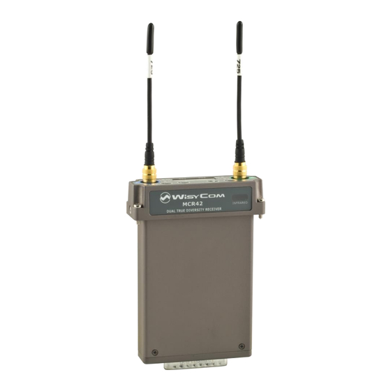
Single-dual true diversity camera receiver
Hide thumbs
Also See for MCR41:
- User manual (45 pages) ,
- Instruction manual (12 pages) ,
- User manual (37 pages)
Table of Contents
Advertisement
Quick Links
Download this manual
See also:
Instruction Manual
Advertisement
Table of Contents

Related Manuals for WisyCom MCR41


Summary of Contents for WisyCom MCR41
- Page 1 MCR41-MCR42 User Manual Single-Dual True Diversity Camera Receiver SN: ________________ rev.10 (rif. FW 3.1) Date: 10 November 2014...
- Page 2 MCR41-MCR42 User Manual rev.10...
-
Page 3: Brief Description
MCR41/42 is a high performance microphone receiver suitable for broadcast and high professional applications. Thanks to Wisycom movable filter technology, MCR42 is able to work in a bandwidth up to 230 MHz, still keeping an exceptional selectivity and intermodulation immunity. -
Page 4: Safety Instruction
MCR41-MCR42 User Manual rev.10 AFETY INSTRUCTION Read this safety instruction and the manual first Follow all instructions and information. Do not lose this manual. Do not use this apparatus under the rain or near the water. -
Page 5: Main Features
Push to Talk (PTT) function with additional audio output signals (patented) (*) Note MCR41 is the version with only one diversity RX board mounted. It supports all features of MCR42 and is compatible with MCR42 Firmware. It is also possible to mount the second Rx board to upgrade a MCR41 to an MCR42. - Page 6 MCR41-MCR42 User Manual rev.10 Above a schematic with an overview of main receiver functions. For each antenna the RF signal is split in the receiver 1 and in the receiver 2 (antenna A and antenna B) with a wide band splitter. In this way any one receiver could be tuned in any frequency of the switching range (typ.
-
Page 7: New Display
MCR41-MCR42 User Manual SER GUIDE NEW DISPLAY Front Panel MCR42 allows an easy and quick configuration using buttons, RGB LED’s and an OLED display. The front panel is functionally divided in the following section: A & B SMA antenna Connector: MCR42 is supplied with a couple of antenna tuned on 400 MHz bandwidth suitable to be used with MCR42-N, MCR42-M, MCR42-L, MCR42-H version. - Page 8 During menu navigation push this button to exit from current menu (escape function). E “Arrow up/sync” BUTTON Push and keep this button to start a synchronization with a Wisycom transmitter (follow instructions on display). Before starting synchronization IRDA must be enabled on Wisycom transmitter.
-
Page 9: Display Menu
HW (HW rev / Options/ Top / Display) / Errors Volume -23÷5dB (step 1 dB) Headphones RX1(L+R)/RX2(L+R)/RX1+RX2(L+R)/RX1(L);RX2(R)/RX1(R);RX2(L) Signal LINE/TSQ>LINE Power On RX1+RX2/ /RX1 Only MCR42 (not MCR41) Only for Slot-in Name (12 characters) BPA42HPN GR: 0÷39 Gr-Ch CH: 0÷59 N: 470.000÷700.000 Frequency M: 566.000÷798.000... -
Page 10: Status Menu
MCR41-MCR42 User Manual rev.10 Using navigation buttons it is possible to quick & easy navigate through the MCR42 menu: - SEL/Exit to enter or exit a level - Arrow up/down to circle on the same level - To save the modified parameters press and hold the SEL /MENU button ( ) until appears the message "SAVED!". - Page 11 Pushing SEL button it’s possible to change freq/GR/CH. From FW 3.0 and above, it’s possible to assign a name and an Expander to a channel using the Wisycom MCR4x Manager v.1.0.1 or above (to understand how to do it, read...
-
Page 12: Main Menu
Restore: that allows to reload 3 different presets (PRESET_1, 2, 3) earlier saved or a Factory preset (a preset load in the Wisycom factory) Save: that allows to save 3 different presets (PRESET_ 1, 2, Each saved preset consists of all user parameters indicated... - Page 13 In the info menu the following information are displayed: Info description example Supply voltage measured 12.0Volt Power: MCR42 dual rx / MCR41 MCR42 dual rx Model: The serial number composed by 1 letter+7 numbers S3536539 Serial: Frequency range according to the MCR band:...
-
Page 14: Advanced Menu
Tone Squelch is not detected. Power on (only for MCR42, not MCR41) Allow to enable both the receivers: Only receiver 1 (Rx1), only receiver (Rx2) or (Rx1 + Rx2). - Page 15 On this menu you can setup the audio companding chipset emulation. ENR is emulating the Philips™ SA572 and PTT digital data of Wisycom transmitters. Other setups can be loaded on request.
- Page 16 Edit RX: Tone Squelch MCR42 is able to detect a digital tone squelch generated by a Wisycom transmitters (ex. MTH400/MTH300/MTP40/ MTP30). Tone squelch ON: when the tone squelch is enabled the audio is muted unless the correct carrier is detected. Tone...
- Page 17 MCR41-MCR42 User Manual Edit RX: Audio Out In Audio Out it’s possible to set the maximum audio output. For MCR42 with Hardware version ≥ 21, the max audio level of the RX1/RX2 output can be set from -30dBu to -10 dBu (in the first selection appears “MIC max lev”) and from -8dBu...
- Page 18 SYNC and SCAN buttons), making easier to pick up the best one. NOTE: As per Wisycom standard, group 00 and group 01 or 09 are special; respectively the “center frequency” (474,482/... MHz) and the intergap frequency (i.e. 470/478/486/... MHz). A scan on...
- Page 19 If Off timeout is set to OFF the display never turn off automatically. Sync: With the MCR41/42 you can synchronize your device with others via the sync function. After the selection of the desiderate receiver that you...
-
Page 20: Error List
MCR41-MCR42 User Manual rev.10 RROR LIST When an error occurs, the receiver shows a message on the display and for some error types increases the errors counter in the info menu inserts the error type and code on the error list in the info menu... -
Page 21: Troubleshooting
RX2 copy2 invalid CRC-16 check of RX2 data (copy 2) automatically replace the detects error. corrupt copy2 with copy1) - send to repair at Wisycom PLL unlocked Error during frequency tuning Repair Centre During the MTK952 initialization phase, - send to repair at Wisycom... -
Page 22: Accessories And Parts
MCR41-MCR42 User Manual rev.10 ACCESSORIES AND PARTS TOP FEED OPTIONS & SLOT IN MCR42 has 4 main audio sources: Audio Line 1&2 AES3 (audio 1&2, 48kHz 24bit) PTT (push to talk) 1&2 Headphone (left/right) Top feed can bring on top on a mini-XLR 5M connector two balanced audio called line1 and line2. - Page 23 MCR41-MCR42 User Manual STAND-ALONE - ACCESSORIES BCA42 FLA42 MCR42 Back Panel Batt. pack Line out 1 / AES3 Line out 2 Headphone Power BPA42-HPN BPA42BAG CDC34 CAM50-2 Power (Hirose) Line out 2 BPA42-PTT PTT out 1 & 2 Line out 1 / AES3...
-
Page 24: Rear Panel
MCR41-MCR42 User Manual rev.10 REAR PANEL The standalone socket BPA42-PTT, BPA42-HPN and BPA42BAG supply the following connections. BPA42-PTT: Stand alone socket BPA42-HPN: Stand alone socket Line 1 AES3 (Line 1 & 2) Line 2 Power Headphone COM pin: 1) GND... - Page 25 MCR41-MCR42 User Manual BPA42BAG: Stand alone socket LINE2 LINE1 Line1 (pigtail) • Analogue audio output electronically balanced, adjustable in a one dB step between -30/-18dBu (depending on the Hardware version) and +6 dBu (nominal) and MAX +12 dBu (peak deviation) •...
-
Page 26: Slot In Sockets
MCR41-MCR42 User Manual rev.10 SLOT IN SOCKETS To transform MCR42 in slot-in compatible for a specific camera you need to use a kit with a rear panel and a flange. Under the item BASE of the submenu INFO you can see the type of rear panel... - Page 27 CAMERA INPUT) CAP51-IK CAP52-IK STAND ALONE HARNESS CABLE STAND ALONE HARNESS CABLE - DB25 (to MCR41) - DB25 (to MCR42) - 1 XLR-3M (isolated with audio tranformer) + - 2 XLR-3M (line output isolated with audio hirose (to camera) tranformer) + hirose (power from camera)
- Page 28 MCR41-MCR42 User Manual rev.10 “Stand-alone" KIT BPA42-K "Stand-alone" KIT for MCR42 BPA42PTT + 2 x CAM 50-2 + CDC34 NOTE: to be used with proper back-panel (i.e. FLA42 or FLA42-SX) ANTENNAS AWN42RA AWM42RA Whip Antenna plastic case 90 deg sma...
- Page 29 NOTE: BPA42-PTT (or -HPN) must be installed FLA42 FLA42-SX Screw-disassemble back-panel Screw-disassemble back-panel For camera-hardware mounting (not drilled) For camera-hardware mounting (for Sony cameras) BCL42 VAP42 Belt clip factory mounted on FLA42 Carrying case for MCR41/42 Eng Systems. MCRMNT CAMERA SHOE MOUNT for MCR41/MCR42...
-
Page 30: Stand Alone Mounting
MCR41-MCR42 User Manual rev.10 Stand Alone Mounting MCR42: Line1 is configured to AES3 output (audio 1 & 2) and PTT - CAM50-2: Line 1 (digital audio 1&2) connected to XLR-3F AES3 (digital input of the camera) - CAM50-3: PTT 1&2 connected to 2 XLR-3F intercom/audio inputs of the camera - CD34: connected to camera power source (if not using the battery pack) MCR42: Line1&2 are configured to analogue output and PTT... - Page 31 MCR41-MCR42 User Manual Slot-in Mounting MCR42: Analogue Audio 1 & 2 audio thru internal slot in Check if your camera is supporting double internal audio! MCR42-EL2 or MCR42-ELC: Digital Audio 1 & 2 thru external AES3 camera input (XLR- - CAM50-41: Top feed Line 1 (digital audio 1&2) connected to XLR-3F AES3 (digital input of the...
- Page 32 USB drivers must be installed on the PC, for further info check on the Download area of the Programmers (UPKxx) on Wisycom website. Check if the version of Wisycom Manager in your PC is the latest version otherwise download the latest version from Wisycom website (http://www.wisycom.com/www3/products/product/mcr42#4...
- Page 33 Push Connect button present in the under part of MRC4x device panel to connect MCR41/42 to the PC How change the name of Receivers Insert the name on the Name box presents in the MCR41/42 device panel (12 characters available) and push the Write button underlying.
- Page 34 MCR41-MCR42 User Manual rev.10 How assign a name and an expander to a Channel Click and then Right click on a name/expander box presents in a Channel column on the grid and select Edit channel name/exp to change name and expander of the channel (a combo box appears with the list of the expanders present on the device).
- Page 35 (click right mouse button) NOTE : The modifications are applied only to the local channels configuration. In order to save them in the MCR41/42 it is necessary to do a Write operation or click right mouse button (write to device)
- Page 36 Select the Channels memory menu and select Clear. This operation clears only the channels memory showed in the grid (local). In order to clear the channels memory in the MCR41/42, after a Clear operation, it is necessary to do a Write operation.
-
Page 37: How To Update The Firmware
MCR41-MCR42 User Manual How to update the firmware: Push FW upgrade button Download the .upf file and load the file using Select button. Click on Start FW upgrade Confirm start FW upgrade pushing Yes... - Page 38 A green bar below the panel shows the progress of this process. Take care do not disconnect the IR communication power MCR41/42 during this process. At the end the new firmware version will be showed on the MCR41/42 device panel.
-
Page 39: Technical Specification
• Noise Reduction ENR (Wisycom Extended-NR) , noise optimized system ENC (Wisycom Extended-NC), voice optimized & with reduced pre-emphasis ⇒ Others, compatible with most systems, thru an internal DSP emulation of SA572, SA575 and Rms envelope compander chip set, fully user programmable •... - Page 40 MCR41-MCR42 User Manual rev.10 - fast blinking, at 12.5% battery capacity. • POWER LEDs 1 multicolour RGB LEDs to easy indicate Rx1 & Rx2 power status: (NEWdisplay) - GREEN/PALE GREEN if "Receivers ON" with external power supply/battery; - GREEN blinking/PALE GREEN blinking if low power supply/ low battery level - RED blinking indicates power supply status of transmitter: ...
- Page 41 MCR41-MCR42 User Manual WISYCOM srl Via Spin 156 I-36060 Romano d’Ezzelino Italy Tel. +39 -0424 -382605 Fax +39 - 0424 - 382733 www.wisycom.com e-mail: sales@wisycom.com...
- Page 42 MCR41-MCR42 User Manual rev.10 ITALY ONLY Obblighi di informazione agli utilizzatori Modello di informazioni agli utenti dei prodotti di tipo “professionale” INFORMAZIONE AGLI UTENTI ai sensi dell’art. 13 del Decreto Legislativo 25 luglio 2005, n. 151 “Attuazione delle Direttive 2002/95/CE, 2002/96/CE e 2003/108/CE, relative alla riduzione dell’uso di sostanze pericolose nelle apparecchiature...
- Page 43 MCR41-MCR42 User Manual...
- Page 44 MCR41-MCR42 User Manual rev.10 Wireless System Communications Via Spin 156 I-36060 Romano d’Ezzelino Italy Tel. +39 -0424 -382605 Fax +39 - 0424 - 382733 www.wisycom.com e-mail: sales@wisycom.com...
Need help?
Do you have a question about the MCR41 and is the answer not in the manual?
Questions and answers