
Related Manuals for Kubota U17-3a


Summary of Contents for Kubota U17-3a
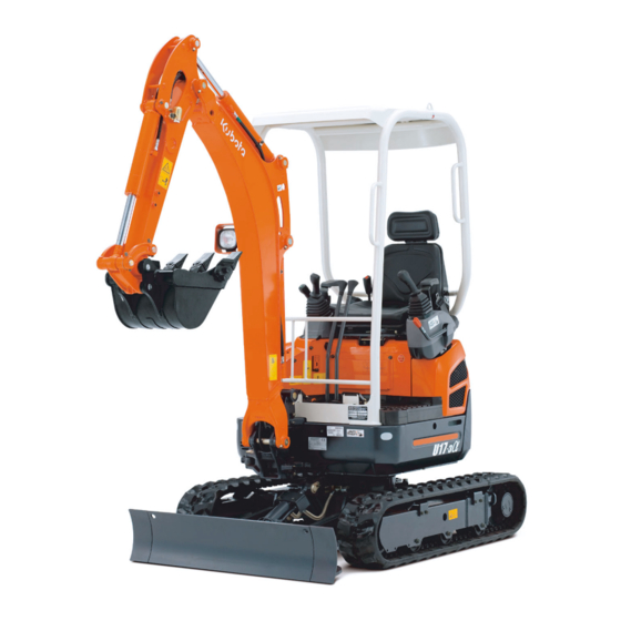
- Page 1 MINI EXCAVATOR MODEL U17-3α Valid as of serial # 25831 OPERATING INSTRUCTIONS W9232-8135-6 - Original - 12/2015...
- Page 2 "Duties, liability and warranty" section (page 14). This documentation neither extends nor re- stricts the contractual warranty. KUBOTA Baumaschinen GmbH reserves the right to change the information contained in this document with re- spect to future technical development without altering the basic characteristics of the excavators described herein and without amending this document.
-
Page 3: Table Of Contents
Tables Table of contents TABLE OF CONTENTS........................3 Abbreviations ............................8 General symbols ............................. 9 GENERAL INFORMATION ......................11 Foreword ..............................11 EC Declaration of Conformity ......................11 Date of issue of the operating instructions ..................12 Operating personnel ..........................12 Location of the operating instructions.................... - Page 4 Tables Other equipment to be found on the machine ..................47 Main battery............................47 Return change valve for direct return flow..................47 Tank filler neck ........................... 47 Main fuses ............................48 Coolant radiator and hydraulic oil radiator..................48 Hydraulic system........................... 49 Engine compartment ..........................
- Page 5 Tables Operating the auxiliary port......................84 Return change valve for direct return flow ..................86 Depressurising the hydraulic system ....................87 Placing out of operation ........................87 Operating other equipment at the operator's place ................88 Operating the rotary beacon (accessories) ..................88 Operating the 12 V plug ........................
- Page 6 Constructive calculation of lifting capacity ..................141 Lifting attachment ..........................142 Load suspension device ........................143 Max. lifting capacity when rotating up to 360°.................. 144 ACCESSORIES ..........................147 KUBOTA Rotary beacon ........................147 KUBOTA pipe safety valve ......................... 147 Note on use ..........................148 W9232-8135-6 12/2015...
- Page 7 Tables KUBOTA quick coupling systems and attachments................ 148 KUBOTA bucket accessories......................148 W9232-8135-6 12/2015...
-
Page 8: Abbreviations
Tables Abbreviations percent kilovolt ° degrees kilowatt °C degree Celsius litre 1/min revolutions per minute l/min litres per minute Ampere noise level operator's place acc. according measured sound power level American Petroleum Institute metre approx. approximately m/s² metre per square second ASTM American Society for Testing and Materials m³... -
Page 9: General Symbols
Tables General symbols Warning light Swivel boom (left) Fuel indicator Swivel boom (right) Engine oil indicator Dozer up Charge indicator Dozer down Glow indicator Lever direction Hydraulic oil Control lever direction Travel speed Rotary beacon Low speed Display selector switch Forward travel Auxiliary port indicator Backward travel... - Page 10 Tables W9232-8135-6 12/2015...
-
Page 11: General Information
General information Foreword These operating instructions apply only to the KUBOTA excavator U17-3α, which complies with the fol- lowing EC Declaration of Conformity (page 11). The safety instructions and the rules and regulations for the use of excavators given in these operating instructions apply to the excavators mentioned in this documentation. -
Page 12: Date Of Issue Of The Operating Instructions
General information Date of issue of the operating instructions The date of issue of the operating instructions is printed on the bottom right of the front page of the book. Operating personnel The duties of personnel with respect to operation, servicing, repairs and safety inspections must be clearly defined by the owner. -
Page 13: Spare Parts
When ordering spare parts, please always provide the following information: Serial # of the excavator and year of construction (see type plate) Designation/type of spare part (see original KUBOTA spare parts catalogue) Part number of the spare part (see original KUBOTA spare parts catalogue) Quantity required Customer number For written orders, please provide this information exactly, or for telephone orders, please have this information ready before calling. -
Page 14: Safety Rules
Safety rules Safety rules Basic safety instructions The EC Use of Work Equipment Directive (2009/104/EC) from 16/09/2009 applies to the operation of the aforementioned excavator. The information in these operating instructions applies for maintenance and repairs. National rules and regulations apply where applicable. Duties, liability and warranty A basic prerequisite for the safe handling and problem-free operation of the excavator is the knowledge of the safe- ty instructions and safety regulations. -
Page 15: Safety Symbols
Safety rules It is the responsibility of the owner to ensure that The safety rules are observed (page 14) Unapproved use (page 16) and unauthorised operation are prevented The excavator is used properly (page 16) and is operated in accordance with the contractual conditions of use. -
Page 16: Approved Use
Safety rules Approved use The excavators specified in these operating instructions may only be used for loosening, excavating, lifting, trans- porting and dumping soils, rocks and other materials, as well as for work with the dozer or with a breaker. The load may be transported largely without driving the excavator. -
Page 17: Special Duties Of The Owner
Disposal must be undertaken in an appropriate way, according to legally prescribed pollution control and safety regulations. If you have questions about the proper disposal or storage of refuse and toxic waste, contact your KUBOTA dealer or a local waste management contractor. -
Page 18: Noise Emission And Vibration
Safety rules Noise emission and vibration The values specified in these operating instructions were identified during the test cycle on an identical machine and are valid for a machine with the standard equipment. The determined values are specified in the Technical Data (page 37). -
Page 19: Safety Instructions On The Excavator
Safety rules Safety instructions on the excavator Keep the safety instructions (labels) on the excavator clean and legible, replacing them if necessary. The positioning of the safety instructions is illustrated in the following figures. Code #: RD517-5788-0 Danger due to electric current! When working in the vicinity of overhead power lines without a suffi- cient safe distance between them and the machine, the electricity can jump onto the machine. - Page 20 Safety rules Code #: RC418-5737-0 Danger of cutting from rotating components! The rotary fan can cut into the extremities. Danger of crushing from rotating components! The rotary belt drive can draw in limbs and crush them. Do not reach into rotating components. Code #: TC030-4958-0 Risk of burns from hot components! Surfaces can be hot and lead to burns.
- Page 21 Safety rules Code #: RC108-5796-0 Attachment point for lifting gear Code #: RG158-5722-0 Mortal danger by crushing! Low safe distance to the excavator and to obstacles can prevent an emergency exit from the danger zone. Crushing by excavator results in severe injury or death.
- Page 22 Safety rules Code #: RD517-5754-0 Risk of fire from inflammable diesel fuel! Inflammatory vapours can occur in the fuel tank, which may go up in flames as a result of an ignition source. Do not use open flames in the vicinity of the fuel tank. Code #: RA238-5744-0 4...
- Page 23 Safety rules Code #: RA011-5753-0 Swivel frame lock Code #: RG138-5717-0 Risk of damage to components! When using a wider or deeper bucket, take good care when swinging or retracting the front attachments to make sure that the bucket does not hit the canopy.
- Page 24 Safety rules Code #: RA118-5776-0 Danger of being crushed by swinging boom! When swinging the boom, there is a danger of getting stuck between the boom and the protective structure or swivel frame. Do not step beyond the front part of the boom swing pedal. Code #: 69198-5784-0 Risk of accidents due to incorrect operation! Improper operating can lead to damage to the excavator, to serious ac-...
-
Page 25: Safety Devices
Safety rules Safety devices Before starting the excavator, all safety devices must be installed properly and operational. No manipulation of safety devices, e.g. the bypassing of limit switches, is allowed. Protective devices may only be removed once the excavator is standing still and the engine is stopped and secured against restarting (starter switch in STOP position and key removed). - Page 26 Safety rules Open the cap on the fuse holder (1) and pull out the fuse. W9232-8135-6 12/2015...
-
Page 27: Protective Structure Of Canopy
The seat belt must be fastened while the excavator is being operated. Do not make any structural changes to the protective structure. In the event of damage, please contact your KUBOTA dealer. (Do not repair!) Never operate the excavator without the protective structure. -
Page 28: Fire Protection
Safety rules Fire protection The excavator components and attachments (in particular the engine and the exhaust system) reach high temperatures even under normal working conditions. An electric installation that is damaged or STOP not properly serviced may lead to flashovers and/or electric arcs. The following fire protection guide- lines may help you ensure the maintenance and efficiency of your equipment and minimise fire haz- ards. -
Page 29: Recovery, Loading And Transport
Recovery, loading and transport Recovery, loading and transport Safety rules for recovery For recovery of the excavator, a towing vehicle of at least the same weight class as the excavator must be used. A tow bar must be used for the recovery. If a tow rope is used, an additional vehicle must also be attached to brake the excavator. -
Page 30: Safety Rules For Transport
Recovery, loading and transport Safety rules for transport The ramps must have a sufficient load-bearing capacity for bearing the weight of the excavator. They must be placed securely on the transport vehicle and fastened. Support the loading area at the rear of the transport vehicle with sufficiently dimensioned supports. The ramps must be wider than the track of the excavator and have footboards on the sides. -
Page 31: Recovery
Recovery, loading and transport Recovery Adhere to the safety rules (page 14) and the safety STOP rules for recovery (page 29). A recovery is only allowed over a short distance and at walking speed (0.5 m/s ~ 1.0 m/s). Attach the tow bar or tow rope to the attachment point (1) on the excavator and to the towing vehicle. - Page 32 Recovery, loading and transport Attach the lifting gear with shackles to the lifting eyes (1) on each side of the dozer. Attach the lifting gear with shackles to the lifting eyes (1) on each side of the boom. Verladen-Kran_U25-4 As soon as the lifting gear is attached to the excavator, press towels between the lifting gear and the excava- tor to protect the excavator.
-
Page 33: Transport On A Flat Bed Trailer
Recovery, loading and transport Transport on a flat bed trailer Adhere to the safety rules (page 14) and the safety STOP rules for transport (page 30). Place the loading ramps on the transport vehicle at an angle of 10° to 15°. Observe the track width. Safely attach the ramps to the transport vehicle to make sure they cannot slide while driv- ing upwards. - Page 34 Recovery, loading and transport For safe attachment, fully retract the arm and bucket and lower the boom until the bucket linkages touch the loading area. Secure the chains and the dozer with wooden beams (2). Secure the excavator against sliding on the transport vehicle with chocks or chains (1) (note the vehicle weight).
-
Page 35: Description Of The Excavator
Description of the excavator Description of the excavator Dimensions The dimensions of the model U17-3α can be found in the following figures and table. W9232-8135-6 12/2015... - Page 36 Description of the excavator All dimensions in mm U17-3a 3540 2440 2310 1910 1440 2750 3545 3840 3900 990/ 990/ 2340 2630 280 1240 1240 3610 2520 2460 2010 1480 2760 3555 3970 4030 Arm version Name Type Arm 950 mm...
-
Page 37: Specifications
Description of the excavator Specifications The specifications for this series are as follows. KUBOTA Excavator Model name U17-3α Canopy Type Rubber crawler Machine weight* 1625 Operating weight** 1700 Capacity (CECE) m³ 0.04 Bucket Width with teeth (without teeth) (400) Water-cooled three-cylinder... -
Page 38: Identification Of The Excavator
Max. pulling capacity at the towing eye Max. vertical load at the towing eye Product ID number PIN Year of construction Engine performance Operating weight Model name KUBOTA Baumaschinen GmbH STEINHAUSER STR. 100 Manufacturer 66482 ZWEIBRÜCKEN GERMANY MODEL SERIAL NO. OPERATING MASS INCL. -
Page 39: Standard Equipment
Description of the excavator Standard equipment This model includes the following standard equipment: Operating instructions Spare parts catalogue Protective cover Filter wrench Grease gun Spare fuse (50 A)\ Guarantee Spare parts catalogue and guarantee can be kept together with the operating instructions (page 12). W9232-8135-6 12/2015... -
Page 40: Assembly And Functions
Assembly and functions Assembly and functions Component overview Swivel frame Dozer cylinder Track frame Dozer Boom Dozer enlargement Arm cylinder Swing block Working lights (canopy, optional) Boom cylinder Canopy Bucket Operator's place Working light (boom) Engine compartment cover Drive sprocket Bucket cylinder Drive unit Idler... -
Page 41: Operator's Place
Assembly and functions Operator's place The operator's place is located in the middle of the machine. It in- cludes the following control elements: Left control console Drive levers and control pedals Right control console Operator's seat Left control console The left control console includes the following components: Left control lever Wrist rest Control lever lock... -
Page 42: Drive Levers And Control Pedals
Assembly and functions Control lever lock To enter and leave the operator’s place, the console must be raised by pulling up on the control lever lock. The engine can only be started if the console is raised. The control levers and the drive levers are only oper- ational when the console is lowered and the control lever lock is in the "Down"... - Page 43 Assembly and functions Description of the components of the right control console Right control lever The right control lever is used to move the boom and the buck- The figure, in conjunction with the following table, shows the functions of the right control lever. Position of control lever Movement Lower boom Raise boom...
-
Page 44: Display And Control Unit
Assembly and functions Display and control unit The display and control unit contains the following displays, buttons 15 16 and indicators: Fuel gauge Charge indicator Coolant temperature indicator Coolant temperature gauge Display Display selector switch Menu button Warning light Set clock indicator Servicing indicator Auxiliary port indicator Pull out key indicator... - Page 45 Assembly and functions Display and control unit - description Fuel gauge The fuel gauge indicates the relative amount of fuel in the tank. Charge indicator The charge indicator lights up when the charging circuit voltage is too low. Coolant temperature indicator The coolant temperature indicator lights up if the temperature in the cooling circuit is elevated.
-
Page 46: Other Equipment At The Operator's Place
Assembly and functions Other equipment at the operator's place Other equipment located at and around the operator's place is described below. Cup holder A cup holder (1) is located on the right-hand rail of the canopy. 12-V socket A 12-V electrical outlet (1) for the connection of an external electric device is located on the right-hand side control console. -
Page 47: Other Equipment To Be Found On The Machine
Assembly and functions Other equipment to be found on the machine Other equipment located on and around the machine is described below. Main battery The vehicle battery (1) is on the left-hand side of the vehicle under the side cover. Return change valve for direct return flow According to the mode of operation of a given attachment, the return flow of the hydraulic oil must occur either via the control valve (indi-... -
Page 48: Main Fuses
Assembly and functions Main fuses The main fuses (1) are located on the left-hand side of the engine compartment, above the coolant expansion reservoir. Coolant radiator and hydraulic oil radiator The coolant radiator and the hydraulic oil radiator are located behind the left side cover. The fill opening for the coolant radiator is located beneath the operator's seat. -
Page 49: Hydraulic System
Assembly and functions Hydraulic system The controls, except the dozer control lever, the boom swing pedal, the auxiliary port pedal and the drive levers, activate a hydraulic oil pilot circuit. The accumulator (figure below/1) makes it possible to lower the boom and the arm in the event of engine failure. The hydraulic oil tank contains the suction filter and the return filter. -
Page 50: Engine Compartment
Assembly and functions Engine compartment The engine compartment (figure below) is positioned at the rear of the swivel frame; it is covered by a lockable hinged cover. Main fuse Fuel filter Fuse box Engine Coolant expansion reservoir Oil dipstick Water separator Oil filter Air filter Engine stop knob... -
Page 51: Operation
Operation Operation Safety rules for operation The safety instructions (page 14) must be followed. The excavator may only be operated according to its approved use (page 16). The excavator may only be operated by trained personnel (page 12). Do not operate the excavator when under the influence of drugs, medication or alcohol. Stop operation when getting tired. -
Page 52: Safety For Children
Operation Safety for children Children are normally attracted to machines and their operation. If children are in the vicinity of the machine and are not at a suitable distance and in the field of vision of the operator, this can lead to STOP serious accidents or even death of the children. -
Page 53: Working In The Vicinity Of Overhead Power Lines
Operation Working in the vicinity of overhead power lines When working with the excavator in the vicinity of overhead power lines and tram lines, a minimum distance as specified in the following table must be maintained between the excavator and its attachments and the power line. Rated voltage [V] Safe distance [m] up to 1 kV... -
Page 54: Getting On The Excavator
Operation Getting on the excavator Risk of injury when entering or leaving the machine! When entering or leaving the machine without a secure halt, you can slip and fall down. STOP - Do not jump up or down the excavator. - Always hold the hand rail tightly with one hand. -
Page 55: Setting The Clock
Operation Setting the clock Turn the starter switch to the RUN position. Press menu button (2). Press display selector switch (1) until the clock is selected on the display (3). By pressing and holding of the display selector switch (1) the follow- ing are selected in this order: year, month, day, 12 or 24 hour indi- cator, hours and minutes for adjusting. -
Page 56: Running In The Excavator
Operation Running in the excavator During the first 50 hours of operation, the following points should be adhered to in all cases: Warm up the excavator at an average engine speed and with a low load; do not let it warm up at idling position. Do not overload the excavator. -
Page 57: Dust Valve - Clean
Operation Dust valve - clean Empty the dust valve (1) on the air filter cover (2) by pressing it together several times. If it is very dirty, remove the air filter and clean it (page 123). Engine oil level - check Pull out the oil dipstick (1) and wipe it with a clean cloth. -
Page 58: Coolant Radiator And Oil Cooler - Check
Operation Coolant radiator and oil cooler - check Walk-around inspection of coolant radiator (1) and oil cooler (2) for tightness and dirt. If there is any dirt etc. on the radiators: Clean coolant radiator (1) and oil coolers (2) from the engine with a water jet or a compressed air gun. -
Page 59: Hydraulic Oil - Check
Operation Hydraulic oil - check All hydraulic cylinders must be extended half way in order to determine the exact hydraulic oil level. Check the oil level in the sight glass (1). The oil level should be half way up the sight glass. Refill hydraulic oil, if necessary (page 132). -
Page 60: Bucket Bolt And Bucket Linkage Bolt - Grease
Operation Bucket bolt and bucket linkage bolt - grease Start the engine (page 66). Position arm and bucket as shown in the figure. Stop the engine (page 67). Lubricate all greasing points (see figure to the right) – see the "Recommended lubricants"... -
Page 61: Other Greasing Points - Grease
Operation Other greasing points - grease Start the engine (page 66). Lower the bucket and the dozer onto the ground. Stop the engine, remove the key. Refer to the "Operating the controls during excavation work" section (page 78). Lubricate all greasing points with grease – see the "Recommended lubricants" section (page 112) – until fresh grease emerges. -
Page 62: Fuel Level - Check
Operation Fuel level - check The fuel gauge (1) indicates the relative amount of fuel in the tank. The less fuel that is left in the fuel tank, the lower the needle of the gauge. Turn the starter switch to the RUN position. Check fuel situation by looking at the fuel gauge on the display and control unit. -
Page 63: Setting Up The Workplace
Operation Setting up the workplace Adjusting the operator's seat Adjust the operator's seat so that fatigue-free and comfortable working is possible. It should be pos- sible to operate all controls safely. Horizontal seat adjustment (seat stand-off) Pull the horizontal seat adjustment lever (1) up and move the seat to the desired position by moving it forward or back, then release the lever. -
Page 64: Seat Belt
Operation Seat belt Buckle up the seat belt (1). Check that the seat belt is fastened tightly. Do not operate the excavator without the seat belt fas- STOP tened. W9232-8135-6 12/2015... -
Page 65: Operating The Excavator
Operation Operating the excavator To operate the excavator safely, see the following sections. Safety instructions for starting the engine The excavator is equipped with an anti-theft system (page 97). When starting the excavator for the first time on a work day, carry out the pre-operational services (page 56). -
Page 66: Starting The Engine
Operation Starting the engine Push throttle lever (1) in the following direction Insert the key into the starter switch (2) and turn it to the RUN position. The excavator is equipped with an anti-theft system. If the excavator is started with the wrong key, the indica- tor “Pull out key”... -
Page 67: Stopping The Engine
Operation The display selector switch (7) allows you to switch between the in- dication of time, engine speed or hours of operation on the display (8). The time (1) indicates the current time of day in hours and minutes. The speed indicator display indication (2) indicates the current en- gine speed. -
Page 68: Observation Of The Displays After Starting And During Operation
Operation Observation of the displays after starting and during operation The operator must observe the display indicators and displays after starting and during operation. The warning light (1) flashes red when a system fault or technical malfunction occurs. Stop the engine im- mediately! The warning light flashes yellow when the system issues a warning. - Page 69 Operation Check if the air intake in the side panel, the radiator, and the oil cooler are very dirty. If necessary: Clean the radiator (page 58). When the machine is being operated at or close to full capacity, the temperature of the coolant can rise a little higher than normal. The coolant temperature indicator (1) flashes and the message appears on the display as shown in the figure on the right.
- Page 70 Operation Also stop the engine immediately if The engine speed rises or drops suddenly Abnormal noises are heard The excavating devices do not respond to the control lever as expected The exhaust fumes are black or white When the engine is still cold, white smoke for a short time is normal. W9232-8135-6 12/2015...
-
Page 71: Adjusting Of The Track Width
Operation Adjusting of the track width Caution - risk of tipping! When carrying out excavating work using the narrow track width, the excavator will be more unstable. STOP The narrow track width should be used only for passing through narrow areas. - As a general rule, perform any excavator work using the standard track width (A). -
Page 72: Adjusting The Dozer Width
Operation Adjusting the dozer width Set blade width to narrow track width Pull out locking bolt (1). Fold away dozer enlargement (2) behind dozer. Reinsert locking bolt (1). Carry out this activity on both sides of the dozer. Set blade width to standard track width Pull out locking bolt (1). -
Page 73: Driving The Excavator
Operation Driving the excavator Adhere to the general safety rules (page 14) and the safety rules for operation (page 51). Carry out the pre-operational services (page 56). Start the engine (page 66). Observe the displays and indicators (page 68). Ensure that the boom and the dozer are in the direc- tion of travel as shown in the figure. - Page 74 Operation Driving If the machine is equipped with a driving warning buzzer (optional), then the buzzer will sound when the drive lever is actuated and while the machine is moving. Push both drive levers forward simultaneously to drive the excavator straight ahead. Releasing the drive le- vers stops the excavator immediately.
- Page 75 Operation Turning Turns are described for the forward direction of travel with the dozer at the front. If the dozer is posi- STOP tioned at the rear, the steering movements should be in the opposite direction. When making turns, be sure nobody is standing within the swing area of the excavator. STOP During driving Pull the left drive lever to neutral, leave the right drive lever...
-
Page 76: Driving Uphill And Downhill
Operation Driving uphill and downhill Exercise extreme caution when driving up and down a STOP slope. Do not use the travel speed button. When driving on gradients, raise the bucket approx. 200 to 400 mm (A) above the ground (see figure). When driving on gradients, let the bucket slide over the ground if the terrain allows it. -
Page 77: Notes For Rubber Crawler Operation
Operation Notes for rubber crawler operation Driving or turning on sharp objects or over steps causes exces- sive wear on the rubber crawlers and will lead to breaking of the rubber crawler or cause the crawler running surface and the steel inserts to be cut. -
Page 78: Excavation Work (Operating The Controls)
Operation Excavation work (operating the controls) Always observe the following safety instructions when working with the excavator. STOP Never crush concrete or boulders by swinging the side boom with the bucket. Do not use the dropping action of the bucket for excavation. Never fully extend the cylinders. -
Page 79: Operating The Dozer
Operation Operating the dozer When working with the dozer, operate both drive le- vers with the left hand and the dozer control lever with the right hand. Push the dozer/extendable track width selector lever (1) all the way down (A). To lift the dozer, pull the dozer control lever (1) back. -
Page 80: Overview Of Control Lever Functions
Operation Overview of control lever functions The figure shows, in connection with the following table, the func- tions of the left and right control levers. Control lever Movement Right control lever Lower boom Raise boom Bucket crowd Bucket dump Left control lever Arm crowd Arm dump Swivel frame to the left... -
Page 81: Operating The Arm
Operation Operating the arm To dump the arm, push the left control lever forward (figure/ ). To crowd the arm, pull the left control lever back (figure/ ). The arm moves as shown in the figure. W9232-8135-6 12/2015... -
Page 82: Operating The Bucket
Operation Operating the bucket To crowd (digging) the bucket, move the right control lever to the left (figure/ ). To dump (empty) the bucket, move the right control lever to the right (figure/ ). When crowding the bucket, take care that the teeth do not hit the dozer. -
Page 83: Swivelling The Swivel Frame
Operation Swivelling the swivel frame No person is allowed to stand in the swivel area during STOP the movement. Swivel carefully to avoid any contact of the front at- tachments with adjacent objects. To turn anticlockwise, move the left control lever to the left (fig- ure/ ). -
Page 84: Operating The Auxiliary Port
Operation Operating the auxiliary port The auxiliary port serves for operating attachments. Only attachments approved by KUBOTA may be used. The attachments must be operated in accord- STOP ance with the operating instructions supplied with them. When using a breaker or other attachment for demolition work where material (e.g. asphalt) is re-... - Page 85 Operation The auxiliary port pedal (1) can be secured against in- advertent operation. If the auxiliary port pedal is not being used, flip the pedal up. When operating the right pedal part (figure/ ) there is an oil flow at the connector B (figure below). When operating the left pedal part (figure/ ) there is an oil flow at the connector A (figure below).
-
Page 86: Return Change Valve For Direct Return Flow
Operation Return change valve for direct return flow The change valve has two settings. When "direct return flow" (3) is enabled, the return flow is directed from the attachment to the hydraulic oil tank via the return filter. The return flow only occurs via the right auxiliary port connector on the arm. -
Page 87: Depressurising The Hydraulic System
Operation Depressurising the hydraulic system Lower front attachments and dozer completely. Turn the starter switch to the STOP position. Wait until the engine has come to a standstill. Turn the starter switch to the RUN position. Do not start the engine! Lower the left control console (1) and make sure that the con- trol lever lock (2) engages. -
Page 88: Operating Other Equipment At The Operator's Place
Operation Operating other equipment at the operator's place Operating the rotary beacon (accessories) The starter switch is in the RUN position. Press the rotary beacon switch (1) to the ON position. The rotary beacon operates as long as the switch remains in this po- sition. -
Page 89: Cold Weather Operation
Operation Cold weather operation Operating the excavator at an ambient temperature below 5 °C is considered cold weather operation. Necessary preparations prior to the winter season If necessary, replace the engine oil and hydraulic oil with those of the viscosities specified for winter. Only use regular diesel fuel with winter additives. -
Page 90: Jump-Starting The Excavator
Operation Jump-starting the excavator Only a vehicle or starting device with a 12 V power supply may be used. A voltage > 12 Volts leads STOP to serious damage to the excavator electronic system. When servicing a battery, always wear suitable protective gloves and eye protection. The operator must remain seated on the operator's place, the battery jumper cables must be con- nected by a second person. -
Page 91: Operating In Emergency Situations
Operation Operating in emergency situations In case of emergency, you can switch off the engine and lower the boom manually. Engine stop knob If the engine cannot be stopped with the key, it can be stopped man- ually. The engine can only be switched off with the starter switch if the throttle lever has been pulled back (idling speed). -
Page 92: Maintenance
Operation Maintenance Refilling the coolant Open the engine compartment cover (page 114). Check the antifreeze content with an antifreeze tester that is qualified for -25 °C. The antifreeze portion of the coolant should not ex- ceed 50 %. Open the coolant expansion reservoir cap when the engine is cool and fill pre-mixed coolant up to the FULL mark (1). -
Page 93: Refuelling The Excavator
Operation Refuelling the excavator When refuelling the excavator, smoking, an open flame, or other sources of ignition are not allowed. The danger zone has to be clearly marked with signs. A fire extinguisher must be kept at hand in the danger zone. -
Page 94: Replacing The Fuses
Observe the following fuse box layout! Check the component function after replacing the fuse. If the fault still persists, contact your KUBOTA specialist dealer. After finishing the work, install the cover on the fuse box and close the engine compartment cover. -
Page 95: Fuse Layout Of The Fuse Box
Operation Fuse layout of the fuse box 1 Horn switch 9 Working light button 2 Engine cut-off switch 30 A 10 Control unit (AC) 10 A 3 Display and control unit (+B) 11 Fuel pump 4 Working lights 15 A 12 Control lever lock 5 Horn 10 A... -
Page 96: Cleaning The Excavator
Operation Cleaning the excavator Before cleaning, shut down the engine and secure it against starting. STOP If a steam cleaner is used for cleaning the excavator, do not direct the steam jet at electric compo- nents. Do not direct a water jet into the intake opening of the air filter. Do not clean the excavator with inflammable liquids. -
Page 97: Replacing The Bucket
Operation Replacing the bucket When replacing the bucket, make sure to wear eye protection, a helmet and protective gloves. STOP During attaching and detaching, chippings and burrs may appear on the bolts or bushings. These STOP may cause severe injuries. Never use your fingers for the alignment of the components (linkage, bucket, arm). -
Page 98: Black (Individual) Key
Use only the special KUBOTA key ring. Other key rings can lead to signal failures between the key and starter switch, and the engine can possibly not start or a key registration cannot be performed. -
Page 99: Registering A Black Key For The Machine
Operation Registering a black key for the machine Register a black key only under the following conditions: Make sure that there are no persons within the excavator's working area. It is essential to warn per- STOP sons in the vicinity of the excavator by briefly honking the horn. Make sure that all operational controls are in the neutral position. - Page 100 Operation Pull out the red key. The insert key indicator blinks. Insert black key into the starter switch. Do not turn the key at this point. If the key is in the RUN position, turn it back to the STOP position. After a short moment, the pull out key indicator blinks.
-
Page 101: Troubleshooting
In the POSSIBLE CAUSE column you will find the possible causes for the malfunction. The REPAIR column indi- cates the required remedial measure. If the fault cannot be remedied by the measure indicated in the REPAIR column, please consult your KUBOTA dealer. Safety rules for troubleshooting Adhere to the general safety rules (page 14) and the safety rules for operation (page 51). -
Page 102: Troubleshooting: Operation
(page 134). Dirty radiator Clean radiator (page 58). Radiator cap (venting) is defective Replace it; consult your KUBOTA dealer if necessary. Engine oil level is too low Check the engine oil level, add en- gine oil if necessary (page 128). -
Page 103: Troubleshooting: Display Indications
Troubleshooting Troubleshooting: Display indications If the machine develops a fault, one of the following messages will appear on the display. In the event of problems please inform your KUBOTA dealer immediately. Display Indicator Problem/Malfunc- Preliminary measure Solution tion CAN system error... - Page 104 No display (yellow) Oil pressure too The engine oil Stop the engine imme- Inform your pressure is too low. diately. The engine KUBOTA dealer im- may have developed mediately. a fault. (red) Overheat The machine is Allow the machine to...
- Page 105 Lever lock system The electrical sys- The engine can be Inform your error tem in the control started but the ma- KUBOTA dealer im- lever lock has de- chine cannot be set in mediately. veloped a fault. motion. (red) Travel speed sys-...
-
Page 106: Maintenance
Careful maintenance of the excavator will guarantee functional safety and a longer service life. Failure to perform the servicing will void the warranty and any liability by KUBOTA. Only use spare parts that are recommended by the manufacturer. Non-approved spare parts of inferior quality or wrong classification result in an increased risk of accidents. -
Page 107: Repair Work On The Machine
The maintenance interval indicator can only be reset by hand. If the maintenance interval indicator has to be replaced because of a defect, the meter is set back to "0". Ask your KUBOTA dealer about this. W9232-8135-6 12/2015... -
Page 108: Operator Maintenance Chart
Maintenance Operator maintenance chart Hours of operation indicator Mainte- Check item Tasks nance in- Page 100 150 200 250 300 350 400 450 500 tervals Walk-around inspection Check Daily Dust valve Cleaning Daily Engine oil level Check Daily Coolant level Check Daily Coolant radiator and oil... - Page 109 Maintenance Hours of operation indicator Mainte- Check item Tasks nance in- Page 550 600 650 700 750 800 850 900 950 1000 tervals Walk-around inspection Check Daily Dust valve Cleaning Daily Engine oil level Check Daily Coolant level Check Daily Coolant radiator and oil Check Daily...
-
Page 110: Skilled Personnel Maintenance Chart
1000 h suction filter In-line filter Change 1000 h Fuel injection - Check Please contact your KUBOTA dealer. 1500 h fuel injector pressure Oil in idler and track roller Change Please contact your KUBOTA dealer. 2000 h Alternator and starter motor Check Please contact your KUBOTA dealer. - Page 111 1000 h suction filter In-line filter Change 1000 h Fuel injection - Check Please contact your KUBOTA dealer. 1500 h fuel injector pressure Oil in idler and track roller Change Please contact your KUBOTA dealer. 2000 h Alternator and starter mo- Check Please contact your KUBOTA dealer.
-
Page 112: Recommended Lubricants
G048 freeze. SAE J1034 LLC-N-50F Always follow the rec- Coolant MB 325.0 KUBOTA mixing ratio ommendations of the ASTM D3306 / 50 % coolant manufacturer D4985 for the mixing ratio. Do not mix with other coolants. - Page 113 Maintenance Recommendation Filled at the factory Note Ambient temper- Quality stand- Viscosity Brand Type ature conditions For preparing the ex- cavator for use in win- ter, fill the fuel tank with winter diesel and ASTM D975 allow the engine to Diesel EN 590 run for a few minutes.
-
Page 114: Make The Maintenance Points Accessible
Maintenance Make the maintenance points accessible Tilting the operator's seat Pull the lever (1) forward and tilt the seat forward. Make sure the seat engages with an audible click when repositioning it. Opening and closing the engine compartment cover Insert the ignition key (1) in the lock (3) of the engine compart- ment cover (2) and turn it clockwise (B). -
Page 115: Opening And Closing The Left Service Cover
Maintenance Opening and closing the left service cover Open the engine compartment cover (page 114). Remove rubber mat and open floor cover (1). Remove the wing nuts (1). Open the left side cover (2). To close the side cover, fold it down and screw it in with the wing nuts. -
Page 116: Attaching And Removing The Engine Compartment Cover Below The Operator's Seat
Maintenance Attaching and removing the engine compartment cover below the operator's seat Tilt the operator's seat (page 114). Unscrew the fastening screws (1) and remove the engine com- partment cover (2). To attach the engine compartment cover, place it into position and tighten the fastening screws. -
Page 117: Maintenance Work For The Operator
Maintenance Maintenance work for the operator Adhere to the instructions for regular servicing to keep the excavator in good condition. Every 50 hours of operation Battery service The battery can become damaged or may explode if the following instructions are not observed. - Never charge or use the battery when the battery electrolyte level is below the minimum mark. -
Page 118: Battery - Load
Maintenance Battery - load Battery acid is very caustic. Avoid contact with battery acid under all circumstances. If clothing, skin or eyes have come into contact with battery acid, rinse the affected parts immediately with water. If the eyes are affected, immediately seek medical attention! Neutralise spilled battery acid immediate- When servicing a battery, always wear suitable protective gloves and eye protection. -
Page 119: Battery - Change
Maintenance Battery - change When disconnecting and connecting the battery, always observe the specified order Risk of short STOP circuit. Open the left side cover (page 115). Remove the negative terminal cover and take off the cable clamp (3). Move the clamp to the side so as to avoid contact with the negative terminal. -
Page 120: Crawler Tension - Check/Adjust
Maintenance Crawler tension - check/adjust When parking an excavator with rubber crawlers, ensure that the ∞ seam ( ) is on top, half way between the idler and the sprocket (see figure/1, "Crawler tension - check", page 120). Clean all parts of the running gear, paying particular attention to stones between the crawler and sprocket or idler. -
Page 121: Crawler Tension - Adjust
Maintenance Crawler tension - adjust Tightening the crawlers Position the grease gun on the grease nipple (1). Pump the grease gun until the specified crawler tension is ob- tained. Loosening the crawlers Loosen the pressure valve (2) carefully. Do not unscrew the pressure valve too quickly or com- pletely. - Page 122 Maintenance Empty the cup (4) and clean with clean diesel fuel. Replace the oil ring (2) and lubricate it with diesel fuel. Assemble the components 1 to 4 in this exact order. Do not forget the red plastic ring (1). Tighten retainer (3) manually, do not use tools.
-
Page 123: Every 200 Hours Of Operation
Maintenance Every 200 hours of operation Swivel bearing - grease Fill grease through the grease nipple (1) with a grease gun. Grease at each 90° position of the swivel bearing. Us- ing the grease gun, apply 5 shots at every position. Refer to the "Recommended lubricants"... -
Page 124: Coolant Hoses And Clamps - Check
Maintenance Clean the outer filter element with compressed air (max. 5 bar) from the inside out without damaging the filter element. Wear eye protection for this service. Insert the outer air filter element and the cover with the TOP mark facing up. Then lock the braces. Close the engine compartment cover. -
Page 125: Fuel Tank - Drain
Maintenance Every 500 hours of operation Fuel tank - drain The drain plug (1) for draining the fuel tank is located underneath the swivel frame, at the front right. Place a container with a minimum capacity of 25 litres under the fuel drain plug. -
Page 126: Servicing By Skilled Personnel
Maintenance Servicing by skilled personnel Every 250 hours of operation V-belt - adjust Remove engine compartment cover under the operator's seat (page 116). Press in the V-belt (1) at position "A". The V-belt must give way for approx. 8 mm. Check condition of the V-belt, it must not have any cracks or other damage. -
Page 127: Every 500 Hours Of Operation
Maintenance Every 500 hours of operation Engine oil and engine oil filter - change The engine oil change must be carried out while the engine is warm. Caution: The engine oil and the oil filter are very hot Risk of scalding. STOP Place an oil pan with a capacity of approx. -
Page 128: Engine Oil - Fill
Maintenance Engine oil - fill Filling capacity (with oil filter): 3.6 l Remove the oil filler cap (1) and fill engine oil. See the "Recom- mended lubricants" section (page 112). Screw in the oil filler cap. Start the engine (page 66). The engine oil pressure indicator must go out as soon as the engine has started. -
Page 129: Fuel Filter Cartridge - Change
Maintenance Remove the drain plug (2) and let the oil drain out completely. Install the drain plug with a new sealing ring on it. Unscrew the filler plug (1). Fill oil as specified in the "Recommended lubricants" section (page 112). The oil level is the lower edge of the thread. Capacity: approx. -
Page 130: Return Filter - Change
Maintenance Return filter - change Pay attention to utmost cleanliness when servicing the hydraulic system. This service may only be carried out after the hydraulic STOP oil has cooled down. The return filter (1) is located in the hydraulic oil tank. Remove the right side cover. -
Page 131: Every 1000 Hours Of Operation
Maintenance Every 1000 hours of operation Hydraulic oil - fill/change Pay attention to utmost cleanliness when servicing the hydraulic system. This service may only be carried out after the hydraulic oil has cooled down. STOP The suction filter must be changed along with the hydraulic oil. The hydraulic oil drain plug (1) is located underneath the swivel frame on the right. -
Page 132: Hydraulic Oil - Fill
Maintenance Hydraulic oil - fill Filling quantity with oil change: approx. 13 l Total hydraulic system capacity: 21 l Remove the oil filler cap (2). Insert a clean funnel with a strainer into the filler port. Fill hydraulic oil to half way up the sight glass (1). Screw in the oil filler cap. -
Page 133: In-Line Filter - Change
Maintenance In-line filter - change Pay attention to utmost cleanliness when servicing the hydraulic system. The replacement procedures are explained with the LH control lever as an example; the RH control lever fil- ter replacement should be performed in the same manner. -
Page 134: Every 2 Years
Maintenance Every 2 years Coolant - change Drain only when engine is cold, otherwise there is a risk of scalding! STOP Capacity: approx. 2.4 l Open the engine compartment cover (page 114). Remove engine compartment cover under the operator's seat (page 116). Remove the radiator cap (1) by turning it anticlockwise. - Page 135 Maintenance Remove the coolant expansion reservoir (1) and drain it, clean- ing it if necessary. Refit the reservoir. Dispose of old coolant according to the applicable en- vironmental protection regulations. Fill the premixed coolant into the radiator and expansion reser- voir.
-
Page 136: Check Bolted Joints
Maintenance Check bolted joints The table below contains the torques for nuts and bolts. These may only be tightened with a torque wrench. Miss- ing torques can be requested from KUBOTA. Tightening torque for screws Nm ( kgf m 4 T (4.6) 7 T (8.8) -
Page 137: Tightening Torque For Hydraulic Pipes
Maintenance Tightening torque for hydraulic pipes Wrench size Torque in Nm Pipe size Thread 30-35 M12x1.5 30-35 M14x1.5 40-45 10x1.5 M16x1.5 60-65 12x1.5 M18x1.5 75-80 15x1.5 M22x1.5 90-100 16x2 M24x1.5 110-120 18x2 M26x1.5 130-140 22x2 M30x2 140-160 25x2.5 M36x2 M22x1.5 60-65 15x1.5 for ED-2 only... -
Page 138: Safety Inspection
Safety inspection Safety inspection All safety inspections are based on the national worker's protection regulations, safety regulations and technical specifications applicable to the country in which the machine is operated. The owner (operator) (page 14) should arrange for the safety inspections to be performed at specified intervals according to national rules and regulations. -
Page 139: Taking Out Of Service And Storage
Taking out of service and storage Taking out of service and storage If the excavator is taken out of service for up to six months, the measures before, during and after taking it out of service must be carried out as described below. If the vehicle is to be taken out of service for a period of over six months, contact the manufacturer for additional measures. -
Page 140: Start-Up After Taking Out Of Service
Taking out of service and storage Start-up after taking out of service If necessary, clean the excavator thoroughly (page 96). Check the hydraulic oil for condensate water. Replace the oil if necessary (page 131). Remove the grease from the piston rods of the hydraulic cylinders. Install the battery (page 119). -
Page 141: Lifting Capacity Of The Excavator
Lifting capacity of the excavator Lifting capacity of the excavator Constructive calculation of lifting capacity The lifting capacity of the excavator is based on ISO 10567 and does not exceed 75 % of the static tipping load or 87 % of the hydraulic lifting capacity of the machine. The lifting capacity is measured at the front bolt of the arm with the arm fully extended. -
Page 142: Lifting Attachment
Load suspensions (e.g. hooks) may only be welded on by suitably skilled personnel. For this type of work, please contact your KUBOTA dealer. At every point of the attachment or the boom, the lifting attachment must withstand a load of two-and-a-half- times its rated lifting load. -
Page 143: Load Suspension Device
Lifting capacity of the excavator Load suspension device A load suspension device with all the characteristics listed below is required: The system must withstand a load two-and-a-half times its rated lifting load, regardless of the point at which that load is applied. The system must be designed in such a way as to practically prevent any objects that have been lifted from falling from the lifting attachment, for example by means of a protective attachment designed for this purpose. -
Page 144: Max. Lifting Capacity When Rotating Up To 360
Lifting capacity of the excavator Max. lifting capacity when rotating up to 360° U17-3α (Canopy) / arm 950 mm and 1100 mm 4 3 60° 3 CW 1 = 1 7 5 kg CW 2 = 2 2 5 kg 2... - Page 145 Lifting capacity of the excavator Lifting capacity over front end, dozer down, only with pipe safety valve on the dozer cylinder MODEL U17-3α SPECIFICATION CANOPY VERSION ARM 950 mm kN (t) LIFT POINT RADIUS (mm) LIFT POINT HEIGHT Mini- Maxi- 1500 2000 2500...
- Page 146 Lifting capacity of the excavator Lifting capacity over front end, dozer down, only with pipe safety valve on the dozer cylinder MODEL U17-3α SPECIFICATION CANOPY VERSION ARM 1100 mm kN (t) LIFT POINT RADIUS (mm) LIFT POINT HEIGHT Mini- Maxi- 1500 2000 2500...
-
Page 147: Accessories
Any manipulation can result in substantial personal in- STOP juries, even death, and is therefore strictly prohibited. The manipulation and repair of the pipe safety valves is prohibited. They may only be replaced by your KUBOTA dealer as a kit. W9232-8135-6... -
Page 148: Note On Use
These factors must be made known to the attachment manufacturer when ordering attach- ments, and be observed by the operator when operating the excavator. Various attachments are nev- ertheless of limited use only. KUBOTA bucket accessories For further bucket accessories, please contact your KUBOTA dealer or authorised retailer. W9232-8135-6 12/2015... - Page 149 Accessories W9232-8135-6 12/2015...
Need help?
Do you have a question about the U17-3a and is the answer not in the manual?
Questions and answers