
Related Manuals for Kubota Super Series 2 KX 91-3


Summary of Contents for Kubota Super Series 2 KX 91-3
- Page 1 OPERATOR'S MANUAL MODELS · U 91-3 35-3 · English (Australia) Code No. RC468-8131-4 1BAAGABAP0280 1BAAGABAP0290 READ AND SAVE THIS MANUAL © PRINTED IN JAPAN KUBOTA Corporation 2007...
- Page 2 LIST OF ABBREVIATION KUBOTA Corporation is ··· Since its inception in 1890, KUBOTA Corporation has grown to rank as one of the major firms in Japan. Abbreviations Description To achieve this status, the company has through the years American Petroleum Institute...
- Page 3 GENERAL SYMBOLS The instruments and operation elements have been marked with a series of symbols in order to simplify the operation of excavator. These symbols are listed below with the respective descriptions. Safety alert Symbol Boom swing (left) Warning lamp ''Fuel level too low'' Boom swing (Right) System lamp Dozer raise...
- Page 4 FOREWORD You are now the proud owner of a KUBOTA Excavator. This excavator is a product of KUBOTA quality engineering and manufacturing. It is made of fine materials and under a rigid quality control system. It will give you long, satisfactory service. To obtain the best use of your excavator, please read this manual carefully.
-
Page 5: Table Of Contents
CONTENTS SAFE OPERATION ....................1 DEALER SERVICE...................... 1 TECHNICAL DATA...................... 2 DESCRIPTION OF MACHINE PARTS................ 3 INSTRUMENT PANEL AND CONTROL ELEMENTS..........4 CHECKS BEFORE START ..................6 DAILY CHECKS....................... 6 CAB TYPE MACHINES ................... 6 Wiper/Washer Switch(CAB type only) ................6 Interior Lamp(CAB type only) ................... - Page 6 CONTENTS TURNS........................22 Pivot Turn ........................22 Spin Turn ........................23 UP AND DOWNHILL DRIVING................23 OPERATION OF THE DOZER ................24 TWO PATTERN SELECTION SYSTEM(TPSS) ............ 24 Pattern Change....................... 24 OPERATION OF THE BOOM................25 OPERATION OF THE ARM................... 26 OPERATION OF THE BUCKET ................
- Page 7 CHANGING THE BUCKET ..................63 FUSES ........................63 Replacing Fuses ......................63 Fuse Capacities and Circuits ..................63 Auxiliary Electric ......................64 Slow Blow Fuse ......................64 TROUBLESHOOTING....................65 KUBOTA I.C.S. NAVIGATION LIST OF MESSAGES ........... 67 OPERATION UNDER COLD WEATHER CONDITIONS .......... 69...
- Page 8 CONTENTS PREPARATION FOR OPERATION IN COLD WEATHER ........69 PROCEDURE AFTER DONE WORK..............69 LONG STORAGE ...................... 70 RECOMMENDED OILS..................... 72 APPENDICES......................73 MAIN DIMENSIONS ....................73 LIFTING CAPACITY ....................74...
- Page 9 Structures, Falling Objects Protective Structures.) with fatigued. a seat belt is installed by KUBOTA. Always use the 7. Check the surroundings carefully before using the seat belt when the machine is equipped with a ROPS/ excavator or when attachments are being attached.
- Page 10 11. Check mechanical parts for correct adjustments and wear. Replace worn or damaged parts immediately. 12. Keep your excavator clean. Heavy soiling, grease, dust and grass can cause fires, accidents or injuries. 13. Use only KUBOTA authorized attachments.
- Page 11 SAFE OPERATION AFTER OPERATION Before leaving the machine, A Park the excavator on a firm, flat and level surface. A Lower the attachments and the dozer blade to the ground. A Stop the engine. A Release pressure trapped in the hydraulic system. A Lock all control levers.
- Page 12 SAFE OPERATION 5. MAINTENANCE SAFE LOADING AND TRANSPORT OF THE EXCAVATOR Before doing maintenance work on the excavator, place the machine on even solid ground, lower the attachments 1. Observe all regulations concerning the transport of to the ground, stop the engine , release pressure trapped excavators on public roads.
- Page 13 The assembly must be done according to the work shop manual of KUBOTA (W.S.M.) for the product involved. 16. KUBOTA uses no parts which are lined with asbestos. Do not use these kind of parts even if they are available and can be installed.
- Page 14 SAFE OPERATION 6. DANGER, WARNING AND CAUTION LABELS...
- Page 15 SAFE OPERATION...
- Page 16 SAFE OPERATION...
- Page 17 SAFE OPERATION...
- Page 18 SAFE OPERATION...
- Page 19 SAFE OPERATION...
- Page 20 SAFE OPERATION...
-
Page 21: Safe Operation
DEALER SERVICE DEALER SERVICE Your KUBOTA dealer is always ready to help so that your excavator offers the best performance. After having carefully read these instruction, you will realize that much of the routine maintenance can be done by yourself. Your KUBOTA dealer is responsible for servicing and the delivery of spare parts. -
Page 22: Technical Data
TECHNICAL DATA TECHNICAL DATA KUBOTA EXCAVATOR Model name KX91-3S2 U35-3S2 Type Canopy Canopy Operating weight (including operator's) 3225 3325 3640 3750 Type Water cooled 4 cycle diesel engine with 3 cylinder KUBOTA KUBOTA Model name D1703-M-E3-BH-US2 D1703-M-E3-BH-US1 Engine Total displacement... -
Page 23: Description Of Machine Parts
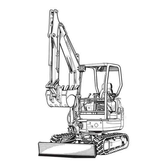
DESCRIPTION OF MACHINE PARTS DESCRIPTION OF MACHINE PARTS DEPICTED CONTENTS (1) Bucket cylinder (10) Boom (2) Arm (11) Arm cylinder (3) Bucket link 2 and 3 (12) Working light (4) Bucket link 1 (13) Canopy (5) Bucket (14) Drive sprocket (6) Boom cylinder (15) Front idler (7) Swing bracket... -
Page 24: Instrument Panel And Control Elements
INSTRUMENT PANEL AND CONTROL ELEMENTS INSTRUMENT PANEL AND CONTROL ELEMENTS B Instrument Panel, Switches DEPICTED CONTENTS (1) Cup holder (U35-3S2) (10) Switch for Auto idle control (2) Service port switch (11) Heater switch (CAB type only) (3) Horn switch (12) Emergency engine stop knob (4) Breaker lock switch (13) Cup holder (KX91-3S2) (5) Travel speed switch... - Page 25 INSTRUMENT PANEL AND CONTROL ELEMENTS B Control Pedals and Levers DEPICTED CONTENTS (1) Drive lever (left) (2) Lock lever (left)* (3) Control lever for front attachments (left) (4) Drive pedal (5) Drive lever (right) (6) Lock lever (right) [Only Canopy type]* (7) Control lever for front attachments (right) (8) Dozer control lever (9) Throttle potentiometer...
-
Page 26: Checks Before Start
CHECKS BEFORE START CHECKS BEFORE START DAILY CHECKS In order to avoid damage, it is important to check the condition of the excavator before starting. To avoid personal injury: A Do maintenance work on the excavator only on level ground with the engine off and the lock lever in the "Lock"... -
Page 27: Heater Switch(Cab Type)
CHECKS BEFORE START BHeater Switch(CAB type) Turn the starter switch to position "RUN" and turn the heater switch clockwise, the heater fan will be activated and the CAB will start to warm up. The heater has two positions - "Low" and "High" -. (1) Heater valve (A) Open (B) Close... -
Page 28: Opening/Closing Of Cab Door(Cab Type Only)
CHECKS BEFORE START BOpening/Closing of CAB Door(CAB type BOpening/Closing of Front CAB only) Window(CAB type only) 1. Unlock the CAB door and pull the knob. Open the CAB door fully until fixed into place. 2. To close the CAB door, push the release lever down To avoid personal injury: and close the door. -
Page 29: Working Light Switch
CHECKS BEFORE START BWorking Light Switch To turn on the working light, set the starter switch to the "RUN" position and press the working light switch. (1) Lock lever 4. To close the window, take the reverse steps 3, 2 and 1. (1) Working light switch BEmergency Hammer(CAB type only) To avoid personal injury:... -
Page 30: Operation Of The Engine
OPERATION OF THE ENGINE OPERATION OF THE ENGINE STARTING THE ENGINE To avoid personal injury: A Read "SAFE OPERATION" at the beginning of To avoid personal injury: this operator's manual. A The operator should not depend solely on the A Obey the danger, warning and caution labels warning lamps, but should always conduct the on the excavator. -
Page 31: Display Selector Switch
OPERATION OF THE ENGINE 4. Insert the key into the starter switch and turn it to the position "RUN". The LCD display shows the figure BDisplay Selector Switch below. The glow lamp will light up while the engine is Press the display selector switch while the engine is preheated and will go out automatically after running. -
Page 32: Charge Lamp
OPERATION OF THE ENGINE BCharge Lamp BLCD Display for Normal Operation This warning lamp lights up if the charging system fails C Fuel gauge while the engine is running. When the starter switch is turned "ON" with the engine off, the lamp lights up, and when the engine gets started, the lamp goes out. -
Page 33: Lcd Display For Warning
OPERATION OF THE ENGINE C Hour-meter Indicates the total operating hours of the machine. To avoid personal injury: How the indicator works A If the fuel is poured too fast, the buzzer may not A The meter advances one hour after an hour of sound according to the fueling process. -
Page 34: Warning Lamp
KUBOTA dealer. (1) Warning lamp (red, yellow) (2) LCD display A Do not just look at the meter, but also carry out the inspection and correction accordingly. A Let your KUBOTA dealer inform you of details concerning care and maintenance. -
Page 35: Starting The Engine Under Cold Conditions
(1) Emergency engine stop knob A If the engine does not stop with the key, contact your KUBOTA dealer. -
Page 36: Starting With An Auxiliary Battery
OPERATION OF THE ENGINE STARTING WITH AN AUXILIARY BATTERY To avoid personal injury: A Battery gases can explode. Do not smoke and keep sparks and flames away. A Do not start the engine with an auxiliary battery if excavator battery is frozen. A Do not connect the black jumper cable to the negative (-) terminal of the excavator battery. -
Page 37: Excavator Operation
EXCAVATOR OPERATION EXCAVATOR OPERATION RUNNING-IN OF THE NEW EXCAVATOR STARTING The operation and care of the new excavator influences its life span. Your new excavator has been carefully checked and tested before leaving the factory. In spite of Adjusting the Operator's Position. this, all movable components must run-in during the first 50 work hours. -
Page 38: Lock Lever
EXCAVATOR OPERATION After starting the engine, bring the lock levers into the "Unlock" position to use drive lever or control lever for front attachments. BLock Lever To avoid personal injury: A To avoid injuries, check safety features all around the excavator. A With the lock lever pulled down, the engine fails to start. -
Page 39: Working Light Switch
EXCAVATOR OPERATION DRIVING BWorking Light Switch When the starter switch is in position "RUN", the light(s) can be switched on by pressing the switch. To avoid personal injury or death: A Before starting the engine, make sure that no one is near the excavator. A Before operating the excavator, check the track direction. -
Page 40: Drive Levers(Right,Left)
EXCAVATOR OPERATION 3. Activate the dozer control lever to raise the dozer. 1. Adjust the engine speed from idling to an intermediate (1) Dozer control lever (A) "Raise" speed. (B) "Lower" 2. Unlock the lock levers and pull in the bucket and hold the bucket about 20 to 40cm above the ground. -
Page 41: Travel Speed Switch
EXCAVATOR OPERATION BTravel Speed Switch To avoid personal injury: A When activating the travel speed switch, it must be pushed down completely. Travel speed will increase when this switch is pushed down. Switching the dual travel speed: 1. Press the travel speed switch. The buzzer beeps and the travel speed changes from first speed to second. -
Page 42: Turns
EXCAVATOR OPERATION (A) "Rotate to remove sand (A) "Travelling forward" (N) "Neutral position" and gravel" 2. While travelling backwards, bring the left drive lever into the neutral position; the excavator will turn to the right. To avoid serious injury or death: A Do not work under the machine in this condition. -
Page 43: Spin Turn
While traveling uphill, keep the lower edge of the bucket approx. 20 to 40cm above the ground. Although the KUBOTA excavator will not slip easily because of the tracks, it is safer to let the bucket slide over the ground while traveling downhill. -
Page 44: Operation Of The Dozer
EXCAVATOR OPERATION OPERATION OF THE DOZER TWO PATTERN SELECTION SYSTEM(TPSS) 1. To raise the dozer, pull back the control lever. Pushing the control lever forwards, lowers the dozer. To avoid personal injury: A Study control lever pattern A and pattern B. Then choose the one which is most familiar A Position the pattern selector lever (located on the right side of operator's seat) in either the... -
Page 45: Operation Of The Boom
EXCAVATOR OPERATION OPERATION OF THE BOOM To raise the boom, pull the attachment control lever back. The boom is equipped with a cushion cylinder which helps prevent excavated material in the bucket from falling out. Low hydraulic oil temperature, (e.g. after starting the engine in cold weather) the cushioning function will be effected for a short period of time (approx. -
Page 46: Operation Of The Arm
EXCAVATOR OPERATION OPERATION OF THE ARM OPERATION OF THE BUCKET Pull back the attachment control lever and the arm will be To dig using the bucket, move the right attachment control pulled in. To move the arm out, push the control lever lever from the neutral position, left. -
Page 47: Unit Swing And Boom Swing Operation
EXCAVATOR OPERATION UNIT SWING AND BOOM SWING BBoom Swing Operation OPERATION 1. Tilt the pedal rearward. 2. Step on the left side of the pedal to swing the boom to the left. To avoid personal injury: 3. Step on the right side of the pedal to swing the boom A When working in groups, always let the others to the right. -
Page 48: Service Port Operation
EXCAVATOR OPERATION SERVICE PORT OPERATION To avoid personal injury: A In the limited flow volume mode, be careful not to get the arm relieved. The service port will otherwise get fully open. A When the lock lever is raised, the service port activation switch is off. A Let the engine warm up after start-up for approx. - Page 49 EXCAVATOR OPERATION C Usual settings A Action mode of service port operation It is possible to select from four action modes of the service port operation by pushing the service port activation switch. Each time the service port activation switch is pushed, the action mode changes from 1 through 4. A When turning the starter key to the "RUN"...
- Page 50 EXCAVATOR OPERATION A Setting of limited flow volume Max. flow volume right and left can be adjusted in 15 stages independently.
- Page 51 EXCAVATOR OPERATION A Service Port Max. Flow Volume KX91-3S2 63.0 Max. Flow Volume (Theoretical L /min.) U35-3S2 60.0 KX91-3S2 23.5 (240) Max. Pressure (kgf/cm ) U35-3S2 24.5 (250)
-
Page 52: One Way Flow Operation
EXCAVATOR OPERATION A When the service port is not used for a long period, dirt particles can settle in the lower part of the service port lines. When the plugs on the service port lines are removed to connect attachments, drain approx. 100 cc (3.4 oz) of oil per side before making connections. -
Page 53: 1-Way Or 2-Way Circuit Selection Valve Operation
EXCAVATOR OPERATION 1-way or 2-way CIRCUIT SELECTION VALVE OPERATION To avoid personal injury: A selection valve which selects 1-way or 2-way circuit of A Stop the engine before removing/changing the service port has been installed on the hydraulic tank. equipment. A Release pressure in the hydraulic system 1. -
Page 54: Auto Idle (Ai) Operation
EXCAVATOR OPERATION AUTO IDLE (AI) OPERATION IMPORTANT INFORMATION ON EXCAVATOR OPERATION 1. Throttle Potentiometer With this potentiometer the operator can adjust the A Do not try to crush concrete or boulders using side engine speed when the Auto Idle control is activated. swings with the bucket. -
Page 55: How To Release Pressure Trapped In The Hydraulic System
EXCAVATOR OPERATION HOW TO RELEASE PRESSURE TRAPPED IN THE HYDRAULIC SYSTEM A Lower the attachments and the dozer blade to the ground. A Turn the key to "STOP" position and shut off the engine. A After stopping the engine, turn the key to "RUN" position. -
Page 56: Transporting The Excavator On A Vehicle
TRANSPORTING THE EXCAVATOR ON A VEHICLE TRANSPORTING THE EXCAVATOR ON A VEHICLE B Transporting on a truck To avoid personal injury or death: A No directional changes should be made when To avoid personal injury or death: the excavator is on the ramp. Should a change A After loading the machine on the truck, lower of direction be necessary, drive off the ramp the bucket and dozer onto the truck bed. - Page 57 TRANSPORTING THE EXCAVATOR ON A VEHICLE 4. Completely align the ramps and the tracks and then drive the excavator slowly up the ramps with the dozer in the front. After ensuring that the tracks are completely on the bed, swing the upper body around to the back of the vehicle.
-
Page 58: Lifting Of The Excavator
LIFTING OF THE EXCAVATOR LIFTING OF THE EXCAVATOR B Lifting Procedure for the Excavator To avoid serious injury or death: A The correct instructions for safe handling are described here. Read these instructions To avoid personal injury or death: carefully before moving the machine. Make A Do not use the hooks on the roof of canopy and sure that the operating personnel read the CAB for lifting the excavator. - Page 59 LIFTING OF THE EXCAVATOR 3. Tackle The weights of the excavators and the recommended tackle for lifting these loads are mentioned in the following table. Choose components having enough strength. KX91-3S2 U35-3S2 Excavator 3330 3750 Weight* 12560 11174 Load / Cable (kgf) (1286) (1139)
-
Page 60: Maintenance
MAINTENANCE MAINTENANCE MAINTENANCE INTERVALS Hour meter indicator Ref. Check points Measures Interval page check Daily check Coolant change every 2 years Fuel check Daily check check Daily check Engine oil every 250 hrs change or every 1 year check Daily check Hydraulic oil change every 1000 hrs... - Page 61 Before operation, make sure that the oil level is between the upper and lower limits of the oil level gauge. Add oil as required. To avoid a shortened service life or burn-out of the engine, use a Kubota-specified oil...
- Page 62 *4 Consult your local KUBOTA Dealer for this service. A The items listed above (@ marked) are registered as emission related critical parts by KUBOTA in the U.S.EPA non- road emission regulation. As the engine owner, you are responsible for the performance of the required...
-
Page 63: Opening And Closing Of Parts
MAINTENANCE OPENING AND CLOSING OF PARTS BOpening/Closing of the Engine Hood BOpening and Closing of the Fuel Tank Cap 1. Open the tank cap cover, insert the starter key and turn counterclockwise. Then turn the tank cap counter- To avoid personal injury: clockwise to open. -
Page 64: Where To Store The Tool And The Grease Gun
MAINTENANCE BWhere to store the Tool and the Grease [KX91-3S2] 1. Remove the mat and the cover of left side step. 2. Store the tools or grease gun in the storage box. (1) Tool box To avoid personal injury: A Stop the engine and remove the key before tilting the seat. -
Page 65: Daily Checks
MAINTENANCE DAILY CHECKS BChecking Fuel Level For your own safety and to assure the long life of your machine, a careful check should be made before each operation. To avoid personal injury: A Stop the engine and remove the key before fuelling. -
Page 66: Checking Engine Oil Level
MAINTENANCE BChecking Hydraulic Oil Level A See "Opening and Closing of the Fuel Tank Cap" and "LCD Display for Normal Operation." To avoid personal injury: A Stop the engine and remove the key before checking the oil level. A Before filling oil, wipe away all sand and dust from around the oil port. -
Page 67: Lubrication Points
MAINTENANCE BLubrication Points To avoid personal injury: A First lower all attachments to the ground then stop the engine and remove the key. A While greasing, take caution not to step on the bucket teeth. A When doing excavation work water, generously grease the following points. -
Page 68: Checking Radiator And Oil Cooler
MAINTENANCE BChecking Radiator and Oil Cooler BChecking Washer Liquid(only for CAB type) If the windows washer is switched on with the washer liquid tank empty, the motor may be damaged. Always To avoid personal injury: keep the tank filled. A Always stop the engine and remove the key before checking the radiator. -
Page 69: Regular Checks And Maintenance Work
REGULAR CHECKS AND MAINTENANCE WORK REGULAR CHECKS AND MAINTENANCE WORK EVERY 50 SERVICE HOURS BDraining Fuel Tank To avoid personal injury: A Before draining the fuel tank, be sure to stop the engine and remove the key. A Do not smoke during inspection. 1. -
Page 70: Battery Charging
REGULAR CHECKS AND MAINTENANCE WORK A Always wear eye protection when working with A When filling battery fluid or distilled water,clean the battery. trash,dust,etc off the top of battery before opening 1. Remove the mat and cover of left side step, check the the battery cap. -
Page 71: Greasing Swing Bearing Teeth
REGULAR CHECKS AND MAINTENANCE WORK BGreasing Swing Bearing Teeth 1. Pump grease with grease gun through the grease nipple (at the right end side). 2. Grease at each 90 (1.58 rad.) position of the swing frame. 3. Fill with approx. 50g of grease (approx. 20 to 30 pumps with the grease gun at each position). -
Page 72: Inspection And Cleaning Air Filter Element
REGULAR CHECKS AND MAINTENANCE WORK BInspection and Cleaning Air Filter Element Open the engine cover and remove the dust cover. Take out only outer element, clean the element, case interior and reassemble. During reassembly, take care to install the dust cover with facing the TOP mark upwards. Do not remove the inner element (safety element). -
Page 73: Air Filter Maintenance
REGULAR CHECKS AND MAINTENANCE WORK BAir Filter Maintenance BGreasing Swing Bearing 1. Fill with grease through the respective grease nipple. 2. Grease at each 90 (1.58 rad.) position of the swing frame. To avoid personal injury: A Wear eye protection. (1) Grease nipple The quickest and safest method of maintenance is the exchange of the paper cartridge. -
Page 74: Checking Fuel Line And Intake Air Line
REGULAR CHECKS AND MAINTENANCE WORK EVERY 250 SERVICE HOURS BChecking Fuel Line and Intake Air Line Do all 50 hour servicing at the same time. 1. Check to see that all lines and hose clamps are tightened and not damaged. BChanging Engine Oil(First Engine Oil 2. -
Page 75: Every 500 Service Hours
REGULAR CHECKS AND MAINTENANCE WORK A Regardless of the service hours, an engine oil change BDrive unit Oil Change(First Oil Change at is due every six months. 100 hours) EVERY 500 SERVICE HOURS Do all 50 and 250 hour servicing at the same time. To avoid personal injury: A Lower to the ground, stop the engine and BReplacing Engine Oil Filter(Replace the... -
Page 76: Replacing Fuel Filter Cartridge
REGULAR CHECKS AND MAINTENANCE WORK BReplacing Fuel Filter Cartridge BReplacing Hydraulic Return Filter Element(first replacement after 250 service hours) To avoid personal injury: A Keep fire away. To avoid personal injury: 1. Remove the filter with the supplied filter wrench. A Remove the oil filter only after the oil in the 2. -
Page 77: Every 1000 Service Hours
REGULAR CHECKS AND MAINTENANCE WORK EVERY 1000 SERVICE HOURS BHydraulic Oil Change(Including Replacing Do all 50, 100, 200, 250 and 500 hour servicing at the Suction Filter and Breather Filter Element same time. in Hydraulic Tank) BHydraulic Oil Check for Machines with Hydraulic Breakers To avoid personal injury: The hydraulic oil change after 1000 operating hours in the... -
Page 78: Replacing Hydraulic Pilot Filter Element
EVERY 1500 SERVICE HOURS BChecking Fuel Injection Nozzle(Injection Pressure) Consult your local KUBOTA Dealer for this service. EVERY 2000 SERVICE HOURS Do all 50, 200, 250, 500 and 1000 hour servicing at the same time. -
Page 79: Every 3000 Service Hours
REGULAR CHECKS AND MAINTENANCE WORK EVERY 3000 SERVICE HOURS BChecking Injection Pump Consult your local KUBOTA Dealer for this service. ANNUAL SERVICE BElectrical Wiring and Fuses Check the terminals periodically for proper connections. Loose wiring or damaged cables can cause improper functioning or short circuiting of the electrical system. -
Page 80: Replacing Fuel Hose
REGULAR CHECKS AND MAINTENANCE WORK 4. The machine has been shipped filled with 50% anti- A To fill the radiator system and the reserve tank, use freeze solution. fresh water and anti-freeze fluid. A When the anti-freeze is mixed with water, the anti- freeze mixing ratio must be less than 50% A Tighten the radiator cap properly. -
Page 81: Other Adjustments And Replacements
OTHER ADJUSTMENTS AND REPLACEMENTS OTHER ADJUSTMENTS AND REPLACEMENTS PURGING FUEL SYSTEM 3. Tension the track in the lifted position, so that the distance "A" (clearance between the center track roller 1. Fill up the excavator with fuel. and the track surface of the track) is 10 to 15 mm (see 2. -
Page 82: Special Information When Using Rubber Tracks
OTHER ADJUSTMENTS AND REPLACEMENTS 3. To check the track tension, the track must be lifted A Track seam from the ground as shown. The track tension is correct The ends of the rubber track are joined with a seam. if the clearance between the outer end of the track When adjusting the tracks, the seam must be roller and the track interior surface corresponds to the positioned on the top midway between the idler and... -
Page 83: Changing The Bucket
Kubota specified bucket. After adjustment is completed: Using the socket wrench, tighten the grease nipple. FUSES Tightening torque must be between 1000 to 1100 kgf-cm. A If the tracks are too tight, wear is increased. -
Page 84: Auxiliary Electric
OTHER ADJUSTMENTS AND REPLACEMENTS BSlow Blow Fuse Slow blow fuse is provided to protect the electrical circuits. If the fusible link is blown, check the electrical circuits for trouble and then replace with a new compatible slow blow fuse. (1) Fuse box (2) Auxiliary electric A (1) Slow blow fuse (50 A) (1) Fuse box... -
Page 85: Troubleshooting
TROUBLESHOOTING TROUBLESHOOTING If the mini-excavator does not show the desired performance, or when trouble arises, refer to the table below and undertake appropriate measures. Trouble Cause Countermeasure Lock levers in "UNLOCK" * Bring lock lever into "LOCK" position. position * Check fuel tank and filter. Fuel is too viscous. - Page 86 TROUBLESHOOTING Trouble Cause Countermeasure Cylinder head gasket is * Replace. damaged (Coolant loss). Water Engine oil level too low * Fill to prescribed level. temperature Engine in red zone Maladjustment of fuel * Readjust ignition timing. (Overheating) injection Use of poor fuel * Use prescribed fuel.
-
Page 87: Kubota I.c.s. Navigation List Of Messages
TROUBLESHOOTING KUBOTA I.C.S. NAVIGATION LIST OF MESSAGES If an error occurs with the machine, one of the following messages appears in the LCD display. In case of a trouble, immediately contact your local dealer for inspection and repair. Warning Problem or failure... - Page 88 A When the key is turned from OFF to RUN repeatedly 10 times, the message disappears. C In case the service hour meter replaced due to any trouble with it, the meter is set to "0". Contact your KUBOTA dealer...
-
Page 89: Operation Under Cold Weather Conditions
OPERATION UNDER COLD WEATHER CONDITIONS OPERATION UNDER COLD WEATHER CONDITIONS PREPARATION FOR OPERATION IN COLD PROCEDURE AFTER DONE WORK WEATHER Clean the excavator thoroughly after work and wipe dry. Otherwise mud and earth on the tracks could freeze if the 1. -
Page 90: Long Storage
LONG STORAGE LONG STORAGE To avoid personal injury: A Do not clean the excavator with the engine running. A To avoid the danger of exhaust fume poisoning, do not operate the engine in a closed building without proper ventilation. A When storing, remove the key from the starter switch to avoid unauthorized persons from operating the excavator and getting injured. - Page 91 Control valve - Pipe, Boom Hydraulic hose (Service port) Pipe, Boom - Pipe, Boom Pipe, Boom - Pipe, Arm Hydraulic hose (Swivel motor) Control valve - Swivel motor To prevent serious damage to the hydraulic system, use only a KUBOTA genuine hydraulic hose.
-
Page 92: Recommended Oils
RECOMMENDED OILS RECOMMENDED OILS 1. Before delivery the hydraulic oil used was an ISO 46 viscosity grade. 2. Use engine oil API service classification CF. 3. Use SAE 90 (API, CLA/GL5) as drive unit oil for all seasons. Application Viscosity Shell Mobil Exxon... -
Page 93: Appendices
APPENDICES APPENDICES MAIN DIMENSIONS With rubber track. Dimensions in parentheses: CAB type models mm KX91-3S2 1550 4940 3530 3185 2390 1310 3485 5245 4945 3525 U35-3S2 1700 3140 2230 3665 5260 [4720] [3315] KX91-3S2 2440 1550 5135 1310 4795 1440 1900 2015 U35-3S2... -
Page 94: Lifting Capacity
LIFTING CAPACITY LIFTING CAPACITY 1. The lifting capacities are based on ISO 10567 and do not exceed 75% of the static tilt load of the machine or 87% of the hydraulic lifting capacity of the machine. 2. The strokes are as follows. (1) The load point corresponds to the front bolt part of the arm. - Page 95 LIFTING CAPACITY...
- Page 96 LIFTING CAPACITY...
- Page 97 LIFTING CAPACITY...
- Page 98 LIFTING CAPACITY...
Need help?
Do you have a question about the Super Series 2 KX 91-3 and is the answer not in the manual?
Questions and answers
hydraulics pressure causing loos to throttle,
Hydraulic pressure issues affecting throttle performance in a Kubota KX 91-3 could be caused by incorrect limited flow volume settings, especially if the engine rpm is not adjusted properly during the setting process. If the flow is limited without matching engine rpm, service port speed may drop, leading to poor attachment performance. Additionally, improper operation of the circuit selection valve or failure to release pressure in the hydraulic system before changing equipment may also contribute to hydraulic pressure problems.
This answer is automatically generated
How can I delete the Engine oil pressure code?