
Related Manuals for Kubota U17-3 Tier4


Summary of Contents for Kubota U17-3 Tier4
- Page 1 MODEL U17-3 English (Australia) 1BAABBKAP0260 Code No. RA238-8130-3 © KUBOTA Corporation 2008 PRINTED IN JAPAN...
-
Page 2: English (Australia)
LIST OF ABBREVIATION Abbreviations Description American Petroleum Institute ASTM American Society for Testing and Materials, USA CECE Commitee for European Construction Machinery German Institute for Standards, Federal Republic of Germany European Standard FOPS Falling Object Protection System Front “Front” means the front view towards the boom and dozer High speed International Organization for Standardization... - Page 3 GENERAL SYMBOLS The instruments and operation elements have been marked with a series of symbols in order to simplify the operation of your excavator. These symbols are listed below with the respective descriptions. Bucket dump “ Safety alert Symbol Boom swing (left) ”...
- Page 4 FOREWORD You are now the proud owner of a KUBOTA excavator. This excavator is a product of KUBOTA quality engineering and manufacturing. It is made of the fi ne materials and under rigid quality control systems. It will give you long, satisfactory service. To obtain the best use of your excavator, please read this manual carefully.
- Page 5 SAFETY FIRST This symbol, the industry’s “Safety Alert Symbol”, is used throughout this manual and on labels on the machine itself to warn of the possibility of personal injury. Read these instructions carefully. It is essential that you read the instructions and safety regulations before you attempt to assemble or use this unit.
-
Page 6: Table Of Contents
CONTENTS TWO PATTERN SELECTION SAFE OPERATION ..... 1 SYSTEM (TPSS) ......31 OPERATION OF THE BOOM ..32 DEALER SERVICE ......13 OPERATION OF THE ARM ..32 OPERATION OF BUCKET ...33 TECHNICAL DATA ......14 SWIVEL (UNIT SWING) OPERATION ......33 Operating Instructions BOOM SWING OPERATION ..34 BOOM SWING PEDAL ....34 DESCRIPTION OF OPERATION OF... - Page 7 EVERY 250 SERVICE HOURS ..56 EVERY 500 SERVICE HOURS ..59 EVERY 1000 SERVICE HOURS ...62 EVERY 1000 SERVICE HOURS OR ONCE A YEAR ......63 EVERY 2000 SERVICE HOURS ..63 ANNUAL SERVICING ....64 BIENNIAL SERVICING ....64 OTHER SERVICING ....65 OTHER ADJUSTMENTS AND REPLACEMENTS .......66 PURGING OF THE FUEL SYSTEM .........66...
-
Page 9: Safe Operation
3. For your safety, ROPS/FOPS (Roll-Over Protective Structures, Falling Objects Protective Structures.) with a seat belt is installed by KUBOTA. Always use the seat belt when the machine is equipped with a ROPS/FOPS. If ROPS is loosened or removed for any reason, make certain all parts are reinstalled correctly. - Page 10 6. Track can be set at the narrow width 39in. (990mm) and the standard width 49in. (1240mm). (for details see “OPERATION OF TRACK WIDTH CHANGE AND DOZER”) Do not operate in narrow track width 39in. (990mm), it makes risk of the excavator tipping over, operate always in standard track width 49in.
- Page 11 2. Start and control the excavator only from 14. Use only KUBOTA authorized the operator’s seat. The driver should not attachments. lean out of his seat when the engine is 15.
- Page 12 6. Do not run the engine in closed or badly 5. Never allow children to operate the ventilated rooms. Carbon monoxide is machine even under adult supervision. 6. Never allow children to play on the colourless, odourless and deadly. machine or on the attachments. Use extra caution when backing up.
- Page 13 5. Do not brake abruptly with the excavator 4. SAFE LOADING AND TRANSPORT loaded. Mortal accidents could happen. OF THE EXCAVATOR 6. If the excavator is used to tow another Observe all regulations concerning the machine, the load must be smaller than transport of excavators on public roads.
- Page 14 Always use safety struts or other appropriate supports. 16. KUBOTA uses no parts which are lined with asbestos. Do not use these kind of parts even if they can be installed.
- Page 15 6. DANGER, WARNING AND CAUTION LABELS (1) Code No. RA238-5748-2 (2) Code No. RA228-5733-1...
- Page 16 (1) Code No. RC418-5753-2 (2) Code No. RA228-5762-1 (3) Code No. RD517-5795-2 [Both sides]...
- Page 17 (1) Code No. RC418-5728-4 (2) Code No. RC418-5727-4 (3) Code No. RD809-5736-1 (4) Code No. RD809-5738-2 (5) Code No. RA228-5751-2 1BAAAARAP1000...
- Page 18 (1) Code No. RC108-5718-1 (2) Code No. RA228-5728-2 [Both sides] (4) Code No. RA228-5776-1 (6) Code No. RC108-5796-1 (3) Code No. RD148-5736-1 [Both sides] Diesel fuel only No fi re (5) Code No. 68328-5735-1 [Both sides] (7) Code No. RB419-5796-2 [Both sides]...
- Page 19 (2) Clean danger, warning and caution labels with soap and water, dry with a soft cloth. (3) Replace damaged or missing danger, warning and caution labels with new labels from your KUBOTA dealer. (4) If a component with danger, warning and caution label (s) affi xed is replaced with new part, make sure new label (s) is (are) attached in the same location (s) as the replaced component.
-
Page 21: Dealer Service
DEALER SERVICE Your KUBOTA dealer is always ready to help so that your excavator offers the best performance. After having carefully read this manual, you will realize that much of the routine maintenance can be done by yourself. Your KUBOTA dealer is responsible for servicing and the delivery of spare parts. -
Page 22: Technical Data
TECHNICAL DATA KUBOTA EXCAVATOR Model name U17-3 Type Canopy Operating weight 3704 (1680) lbs.(kg) (including operator's) Water cooled 4 cycle diesel engine with 3 cylinder Type KUBOTA D902 Model name Total displacement 898 (54.8) Engine cc (cu.in) Engine power 12.7 (17.0) -
Page 23: Description Of Machine Parts
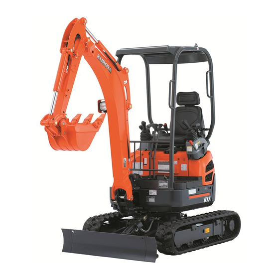
DESCRIPTION OF MACHINE PARTS DEPICTED CONTENTS (1) Arm (2) Bucket cylinder (3) Bucket link (4) Bucket (5) Swing bracket (6) Dozer cylinder (7) Dozer (8) Arm cylinder (9) Boom (10) Working light (11) Canopy (Rops / Fops) (12) Operator’s seat (13) Boom cylinder (14) Drive sprocket (15) Track roller... -
Page 24: Instrument Panel And Control Elements
INSTRUMENT PANEL AND CONTROL ELEMENTS Instrument Panel, Switches DEPICTED CONTENTS (1) Horn switch (2) Starter switch (3) Warning lamp (4) LCD display (5) Working light switch (6) Display selector switch (7) Working light... -
Page 25: Control Pedals And Levers
Control Pedals and Levers DEPICTED CONTENTS (1) Drive lever (left) (2) Control lever for front attachments (left) (3) Lock lever for attachment control (4) Service port pedal (5) Drive lever (right) (6) Control lever for front attachments (right) (7) Two travel speed switch (8) Control lever for dozer or track width (9) Throttle lever (10) Boom swing pedal... -
Page 26: Before Start
BEFORE START DAILY CHECKS TILTING THE SEAT In order to avoid damage, it is important to CAUTION check the condition of the excavator before To avoid personal injury: starting. Lock the lever for attachment control when tilting the seat. CAUTION To avoid personal injury: To tilt the seat forward, pull the seat tilting Do maintenance work on the... - Page 27 2. To close the rear bonnet, make sure the Opening/closing the left bonnet left bonnet is locked, unlock the lock Remove the rubber mat off the left lever and push the rear bonnet until it bonnet side. Then undo the step fi xture. clicks into position.
- Page 28 Opening and Closing of the Fuel Keeping the Tools Tank Cover To open the tank cover, fi rst insert the key into the key slot and turn it counterclockwise to unlock, then open the tank cover upward. For closing, return the tank cover to original position and turn the key clockwise to lock, then remove the key.
-
Page 29: Handling The Safety Devices
HANDLING THE SAFETY DEVICES Control lever lock CAUTION When the excavator is not used or left unattended, be sure to place the lock lever in "Lock" position . The attachment control lever lock is located on the left side. (1) Lock lever for attachment (A) “Lock”... -
Page 30: Operation Of The Engine
OPERATION OF THE ENGINE STARTING THE ENGINE CAUTION To avoid personal injury: Read “SAFE OPERATION” at CAUTION the beginning of this operator's To avoid personal injury: manual. operator should Obey the danger, warning and depend solely on the alarm caution labels on the excavator. lamps, should always... -
Page 31: Display Selector Switch
3. Pull the lock lever all the way back. (lock Display Selector Switch position). Press the display selector switch, and the 4. Insert the key into the starter switch electronic meter’s LCD display will change and turn it to the "RUN" position, and from one indication mode to the other. - Page 32 Charge Lamp LCD Display for Normal Operation This warning lamp lights up if the charging Fuel gauge system fails while the engine is running. When the starter switch is turned ”ON” with CAUTION the engine off, the lamp lights up, and when To avoid personal injury: the engine gets started, the lamp goes out.
- Page 33 Procedure 3. Stop the engine and check the following points (1)-(3). Press the work light switch or the display selector switch on the meter (1) Low coolant level or leak with the key OFF . (Keep the key at OFF .) (2) Fan belt tension (3) Mud or dust deposits on radiator 2.
- Page 34 Sudden abnormal noises are heard. Exhaust is black. Alarm lamp for engine oil lights up during operation. IMPORTANT: In these cases, the excavator must be checked and serviced by your local KUBOTA dealer. (1) Warning lamp (red, yellow) (2) LCD display...
-
Page 35: Starting The Engine Under Cold Conditions
IMPORTANT: Precautions in case of overheat Let the engine warm up after start- up for approx. 10 minutes under no CAUTION load conditions. If the hydraulic fl uid Do not open the radiator cap temperature is too low, the operations during and just after operation. -
Page 36: Starting With An Auxiliary Battery
NOTE: If the engine does not stop with the key, contact your KUBOTA dealer. STARTING WITH AN AUXILIARY BATTERY CAUTION To avoid personal injury: Battery gases can explode. Do not smoke and keep sparks and fl ames away. (1) Low battery... -
Page 37: Excavator Operation
EXCAVATOR OPERATION CONTROL OBSERVATIONS DURING Oil Change in the Run-in Stage The lubrication oil plays a specifi c and OPERATION important role during the run-in phase of the excavator. The numerous movable parts are Stop the Engine immediately if: not yet run-in, so many fi ne metal particles Sudden increase or decrease in engine are generated and cause damage and rpm's occurs. - Page 38 times until the arrow mark comes to the 1. Adjusting the Operator’s Seat center of the weight indicator (3). Move up the lever (2) toward G from the Operator's Seat center (free state), and the spring force gets stronger. Move it down toward F , CAUTION and the spring force gets weaker.
-
Page 39: Two Pattern Selection System (Tpss)
Working Light Switch TWO PATTERN SELECTION If the key in “RUN” position, the lights can be SYSTEM (TPSS) switched on by pressing the switch. CAUTION To avoid personal injury: Study control lever pattern A and pattern B. Then choose the one which is most familiar Position the pattern selector lever in either the left side... -
Page 40: Operation Of The Boom
IMPORTANT: Lever Position Pattern A Pattern B When lowering the boom, make sure Boom down Arm up that it does not hit the dozer and that the Attachment Boom up Arm crowd bucket teeth do not touch the dozer. Control Lever Swing left Swing left (Left) -
Page 41: Operation Of Bucket
OPERATION OF BUCKET SWIVEL (UNIT SWING) OPERATION To dig using the bucket, move the right CAUTION attachment control lever from the neutral To avoid personal injury: position left. Moving the control lever right, When working groups, moves the bucket outwards and dumps its always let the others know contents. -
Page 42: Boom Swing Operation
BOOM SWING OPERATION BOOM SWING PEDAL Step on the left side of the pedal to swing WARNING the boom to the left. To avoid personal injury or death: 2. Step on the right side of the pedal to Always keep your toes within swing the boom to the right. -
Page 43: Operation Of Track Width Change And Dozer
2. Push the control lever forward. OPERATION OF TRACK WIDTH ... The track width increases [from 39in. CHANGE AND DOZER to 49in. (990 mm to 1240 mm)]. Pull the control lever backward..The track width reduces [from 49in. to CAUTION 39in. -
Page 44: Operation Of The Dozer
Adjustment of the Dozer Width Operation of the Dozer For changing from standard width to narrow NOTE: width: While operating the dozer, the track width Pull out the fi xing pin (2) and remove the change / dozer select lever must be set extension dozer (1). -
Page 45: Service Port Operation
NOTE: SERVICE PORT OPERATION When the service port is not in use, fold the service port pedal forward. The pedal This pedal is used to operate attachments gets fi xed and can be used as footrest. such as breakers. (1) Service port pedal (A) “Fix”... -
Page 46: Throttle Lever
To lock the swing frame with the track Drive Levers (Right, Left) frame, engage the swing lock pin. 2. Adjust the engine speed from idling to WARNING an intermediate speed. To avoid personal injury or death: 3. Unlock the lock lever for attachment swing frame control. -
Page 47: Turns
Travel Speed Switch TURNS CAUTION CAUTION To avoid personal injury: To avoid personal injury: When activating travel Do not change direction on speed switch, must steep slopes, or the excavator pushed down completely. could tip over. Before changing direction, Travel speed will increase when the switch is beware of people in the working pushed down. - Page 48 Change of Direction while Travelling Spin Turn While travelling forwards, bring the left When both drive levers are activated in (right) drive lever in the neutral position; the opposite directions, both track will the excavator will turn to the left (right). rotate with the same speed but in opposite directions.
-
Page 49: Up And Downhill Travelling
While travelling uphill, keep the lower edge of the bucket approx. 8 to 16in. (20 to 40cm) above the ground. Although the KUBOTA excavator will not slip easily because of the tracks, it is safer to let the bucket slide over the ground while travelling downhill. -
Page 50: Important Information On Excavator Operation
IMPORTANT INFORMATION ON If the water or mud level reaches higher than the top of the tracks, the swivel EXCAVATOR OPERATION bearing, swivel motor gear and ring gear may be exposed to mud, water and other Do not try to crush concrete or boulders foreign objects. -
Page 51: Transporting The Excavator On A Truck
TRANSPORTING THE EXCAVATOR ON A TRUCK Transporting on a Truck DANGER To avoid personal injury or death: No directional changes should WARNING be made when the excavator is To avoid personal injury or death: on the ramp. Should a change After loading the machine on of direction be necessary, drive the truck, lower the bucket and... - Page 52 3. For additional safety, use blocks or supports under the ramps and the truck bed. 4. Align the ramps and the tracks and then drive the excavator slowly up the ramps. After ensuring that the tracks are completely on the truck bed, swivel the upper body around to the back of the truck.
-
Page 53: Lifting Of The Excavator
LIFTING OF THE EXCAVATOR Safety Aspects when Lifting with DANGER Cables or Straps To avoid personal injury or death: The correct instructions for Abide by following steps when lifting: safe handling are described Do not lift loads that exceed the here. - Page 54 Lifting Procedure Excavator WARNING To avoid personal injury or death. Do not use the hooks on the roof of canopy and cabin for lifting the excavator. General guidelines for lifting Lifting position. (see illustration) 1) Pull in the boom towards rear. 2) Pull in the arm completely.
-
Page 55: Maintenance
MAINTENANCE MAINTENANCE INTERVALS Hour meter indicator Ref. Checkpoints Interval Measures page 50 100 150 200 250 300 350 400 450 500 550 600 1000 2000 1 Fuel check Daily check check Daily check 2 Engine oil change every 250 hrs check Daily check 3 Hydraulic oil**... - Page 56 “EVERY 1000 SERVICE HOURS” in “REGULAR CHECKS AND MAINTENANCE WORK” . The items listed above (@ marked) are registered as emission related critical parts by KUBOTA in the U.S.EPA nonroad emission regulation. As the engine owner, you are responsible for the performance of the required maintenance on the engine according to the above instruction.
-
Page 57: Daily Checks
NOTE: DAILY CHECKS Before delivery coolant were fi lled with 50 % water and 50 % antifreeze. For your own safety and to assure the long life of your machine, a careful check should Check Fuel Level be made before each operation. CAUTION Coolant Check To avoid personal injury:... - Page 58 2. If necessary, open the tank cap with the Check Engine Oil Level starter key, and add fuel. CAUTION To avoid personal injury: Stop the engine and remove the key before checking the oil level. Insert the engine oil dipstick fully into the prepared opening, remove again and check the oil level;...
-
Page 59: Check Hydraulic Oil Level
4. Should the oil level be too low, fi ll oil Check Hydraulic Oil Level through the oil port before starting the engine. This step is important for the CAUTION protection of the hydraulic system. To avoid personal injury: First lower all attachments on the ground then stop the engine and remove the key. - Page 60 Lubrication Points CAUTION To avoid personal injury: First lower all attachments on the ground then stop the engine and remove the key. While greasing, take care not to step on the bucket teeth. When doing excavation work in water, generously grease the following points.
- Page 61 Check Radiator and Oil Cooler Cleaning of Engine and Electrical Wiring CAUTION To avoid personal injury: CAUTION Always stop the engine and To avoid personal injury: remove the key before checking Always stop the engine and the radiator and the oil cooler. remove the key before cleaning Wear protection...
-
Page 62: Regular Checks And Maintenance Work
REGULAR CHECKS AND MAINTENANCE WORK 4. A boost charge is only for emergencies. EVERY 50 SERVICE HOURS It will partially charge the battery at a high rate and in a short time. Battery Charging When using a boost-charged battery, it is necessary to recharge the battery as CAUTION early as possible. - Page 63 Inspection and Cleaning of the Air Air Filter Maintenance Filter Element Open the engine bonnet and remove the CAUTION To avoid personal injury: dust-cover. Take out only outer element, Wear eye protection. clean element, case interior reassemble. During reassembly, take care to install the dust-cover so that its TOP mark (arrow) faces up-wards.
-
Page 64: Every 200 Service Hours
EVERY 200 SERVICE HOURS EVERY 250 SERVICE HOURS Do all 50 and 100 hour servicing at the same Do all 50 hour servicing at the same time. time. Engine Oil Change (First Engine Greasing of the Swing Bearing Change after Service Grease through the respective grease Hours) - Page 65 Checking the Fan Belt Tension Check and adjustment of the fan belt tension CAUTION To avoid personal injury: First stop the engine and remove the key. After servicing, make sure to replace the belt cover in its original position. (1) Engine oil dipstick (A) Required level Press the fan belt down in the middle, 4.
- Page 66 IMPORTANT: Replacing Engine Oil Filter If the engine is run with a loose fan (First Engine Oil Filter Change belt, the belt could slip and cause after 50 Service Hours) overheating of the engine or insuffi cient Replace the oil fi lter cartridge at the battery charging.
-
Page 67: Every 500 Service Hours
EVERY 500 SERVICE HOURS Replacing of Fuel Filter CAUTION Do all 50, 100 and 250 hour servicing at the To avoid personal injury: same time. Keep fi re away. Drive unit Oil Change Close the cock of the water separator. (First Oil Change at 100 hours) Remove the fi... - Page 68 fl uid cooled down. level is below the LOWER (lower limit level) mark. Otherwise, the Contact your KUBOTA dealer for details. battery component parts may prematurely deteriorate, which shorten battery's...
- Page 69 Check the battery fl uid level and add Draining water of the Fuel Tank distilled water if necessary. 2. Clean the battery caps (ventilation CAUTION holes). To avoid personal injury: Before draining water of the fuel tank, be sure to stop the engine and remove the key.
-
Page 70: Every 1000 Service Hours
2. Remove the drain plug on the underside EVERY 1000 SERVICE HOURS of the hydraulic tank and drain the oil. Do all 50, 100, 200, 250 and 500 hour servicing at the same time. Cleaning of the Pipe fi lter of the Hydraulic Pilot System Dust and dirt collect on the concave side of the fi... -
Page 71: Every 1000 Service Hours Or Once A Year
Do all 50, 200, 250, 500 and 1000 hour more every 200 Hrs. servicing at the same time. Chang Front Idler and Track Roller NOTE: Contact your KUBOTA dealer for details. Check the Dynamo and Starter Motor NOTE: Contact your KUBOTA dealer for details. -
Page 72: Annual Servicing
Let the engine idle for about 5 min., stop having been replaced, contact your nearest the engine and remove the key then KUBOTA dealer. Never use a fuse other than check the coolant level. specifi ed. 4. The machine has been shipped fi lled with 50% anti-freeze solution. -
Page 73: Other Servicing
OTHER SERVICING approx. 0.71 US gal (2.7 L) Coolant volumes (Reserve tank: approx. 0.16 US gal (0.6 L) Cleaning the Track Frame Slide Pipes When the slide pipes of the track frame are IMPORTANT: clogged or adhered with soil or sand, clean Do not operate the engine without the slide pipes in the following manner coolant. -
Page 74: Other Adjustments And Replacements
OTHER ADJUSTMENTS AND REPLACEMENTS PURGING OF THE FUEL SYSTEM ADJUSTMENT OF TRACKS Fill up the excavator with fuel. To loosen the tracks, follow the following 2. Turn the starter key to the “RUN” procedure: position. 3. The fuel system will CAUTION automatically be purged within one To avoid personal injury:... - Page 75 Tension the tracks as specifi ed: Apply grease (2) to the grease nipple (1). (1) Grease nipple (2) Grease gun (1) Seam (Mark “o o”) (A) 0.4 to 0.6 in. (10 to 15 mm) 2. Tension the track in the lifted position, so IMPORTANT: that the distance "A"...
-
Page 76: Exchange Of Bucket Teeth And Side Cutters [Jpn Bucket Version]
Special Information when Using EXCHANGE OF BUCKET TEETH Rubber Tracks AND SIDE CUTTERS [JPN BUCKET When turning, make a slow swing turn. VERSION] Avoid spin turns to lessen lug wear and entry of dirt. Bucket Tooth Replacement 2. The relief valve may be activated if too much dirt and sand clog the tracks. - Page 77 4. Mount a new point on the adapter. Replacing the Bucket CAUTION To avoid personal injury: The bucket can tilt over and cause accidents if in an unstable position. Therefore: 1) Only change the bucket if no other persons are in the area.
-
Page 78: Fuses
FUSES Slow Blow Fuse Slow blow fuse is provided to protect the electrical circuits. If the fusible link is blown, Replacing Fuses check the electrical circuits for trouble and Remove the cover of the fuse box. then replace with a new compatible slow 2. -
Page 79: Troubleshooting
TROUBLESHOOTING If the excavator does not show the desired performance, or when trouble arises, refer to the table below and undertake appropriate measures. Trouble Cause Countermeasure * Check fuel tank and filter Fuel is too viscous * Remove impurities and water * If necessary, replace filter * Remove water from the fuel tank * Check fuel pipe joint bolts and nuts for... - Page 80 Trouble Cause Countermeasure Boom, arm, Hydraulic oil level too low * Add oil bucket, drive, swing and dozer Leakages of hoses and / or power is too low * Replace hose or joint joints Non-function of Swing lock pin is in lock * Remove swing lock pin in unlock swing motor position...
- Page 81 KUBOTA I.C.S. NAVIGATION LIST OF MESSAGES If an error occurs with the machine, one of the following messages appears in the LCD display. In case of a trouble, immediately contact your local dealer for inspection and repair. Warning Problem or failure...
- Page 82 When the key is turned from OFF to RUN repeatedly 10 times, the message disappears. In case the service hour meter replaced due to any trouble with it, the meter is set to ”0” . Contact your KUBOTA dealer for details.
-
Page 83: Operation Under Cold Weather Conditions
OPERATION UNDER COLD WEATHER CONDITIONS PREPARATION FOR OPERATION IN PROCEDURE AFTER DONE WORK COLD WEATHER Clean the excavator thoroughly after work and wipe dry. Otherwise mud and earth on Replace engine oil and hydraulic oil with the tracks could freeze if the temperature those of viscosities suitable for cold drops below the 0ºC mark. -
Page 84: Long Storage
LONG STORAGE CAUTION To avoid personal injury: Do not clean the excavator with the engine running. To avoid the danger of exhaust fume poisoning, do not operate the engine in a closed building without proper ventilation. When storing, remove the key from the starter switch to avoid unauthorized persons from operating the excavator and getting injured. - Page 85 Periodic replacement of important component parts To ensure safety in operation, you are strongly requested to inspect and service the machine at regular intervals. For added safety, ask your KUBOTA dealer to replace the following important component parts. These parts are prone to degradation in material or subject to wear and tear with time. It is diffi cult to judge how much they have been affected at regular inspection.
-
Page 86: Recommended Oils
RECOMMENDED OILS IMPORTANT 1. Before delivery, the hydraulic oil used was an ISO 46 viscosity grade. 2. Use engine oil API service classifi cation CD, CE or CF . 3. Use SAE 90 (API, CLA/GL5) as drive unit oil for all seasons. Application Viscosity Shell Mobil... -
Page 87: Main Dimensions
MAIN DIMENSIONS in. (mm) 20.08 15.2 24.4 39.0 139.0 96.1 90.9 75.2 56.7 92.1 11.0 108.3 31.3 139.6 151.2 153.5 48.8 48.8 (510) (385) (620) (990) (3540) (2440) (2310) (1910) (1440) (2340) (280) (190) (2750) (795) (3545) (3840) (3900) 990/ 990/ 1240 1240... -
Page 88: Lifting Capacity
LIFTING CAPACITY The lifting capacities are based on ISO 10567 and do not exceed 75% of the static tilt load of the machine or 87% of the hydraulic lifting capacity of the machine. 2. The strokes are as follows. 1) The load point corresponds to the front bolt part of the arm. 2) The machine positions are (i) over –... - Page 89 U17-3 ROPS CANOPY RUBBER TRACK LIFTING CAPACITY OVER-FRONT BLADE DOWN Unit=kN (kg) LIFT POINT RADIUS (m) LIFTING POINT HEIGHT (m) 3.1 (310) 2.6 (260) 3.0 (300) 3.8 (380) 4.4 (440) 3.4 (340) 3.1 (310) 5.2 (530) 3.9 (390) 3.2 (320) 5.8 (590) 4.1 (410) 3.2 (320)
Need help?
Do you have a question about the U17-3 Tier4 and is the answer not in the manual?
Questions and answers
Trying to look up Kubota U17 fuse box diagram