
Related Manuals for Kubota U35-4


Summary of Contents for Kubota U35-4
- Page 1 OPERATOR'S MANUAL MODEL 35-4 English (Australia) 1BAAEALAP0090 1BAAEALAP0100 Code No. RC788-8131-5 1BAAEALAP0090.eps 1BAAEALAP0100 READ AND SAVE THIS MANUAL PRINTED IN JAPAN © KUBOTA Corporation 2013...
- Page 2 Operator Protective Guards of Top Guard Level I (Top Guard Level I) Revolutions Per Minute ROPS Roll-Over Protective Structures Society of Automotive Engineers, USA TPSS Two Pattern Selection System Auto Idle U35-4 AW . A . 11 - 13 . 1 . AK...
- Page 3 GENERAL SYMBOLS The instruments and operation elements have been marked with a series of symbols in order to simplify the operation of excavator. These symbols are listed below with the respective descriptions. Safety alert Symbol Boom swing (left) Warning lamp ''Fuel level too low'' Boom swing (Right) System lamp Dozer raise...
- Page 4 FOREWORD You are now the proud owner of a KUBOTA Excavator. This excavator is a product of KUBOTA quality engineering and manufacturing. It is made of fine materials and under a rigid quality control system. It will give you long, satisfactory service. To obtain the best use of your excavator, please read this manual carefully.
-
Page 5: Table Of Contents
CONTENTS SAFE OPERATION .................... DEALER SERVICE...................... 1 TECHNICAL DATA...................... 3 DESCRIPTION OF MACHINE PARTS................ 4 INSTRUMENT PANEL AND CONTROL ELEMENTS..........5 CHECKS BEFORE START ..................7 DAILY CHECKS....................... 7 CHECKING THE DEVICES ..................7 Starter Switch ........................7 Display Selector Switch ....................8 LCD for Normal Operation .................... - Page 6 CONTENTS CHECK POINTS AFTER STARTING THE ENGINE ..........26 STOPPING THE ENGINE..................27 Engine Stop Button......................27 Precautions in case of Overheat..................27 EXCAVATOR OPERATION ..................28 RUNNING-IN OF THE NEW EXCAVATOR............28 Do not Work with Full Engine Rpm's or Full Loads during the First 50 Working Hours.. 28 Oil Change in the Run-in Stage ..................
- Page 7 CONTENTS Checking Coolant Level....................58 Checking Fuel Level ....................... 58 Checking Engine Oil Level....................59 Checking Hydraulic Oil Level..................59 Checking V-belt ......................60 Checking Radiator and Oil Cooler .................. 60 Checking Washer Liquid....................61 Checking and Cleaning Engine and Electrical Wiring............. 61 Washing Whole Machine ....................
- Page 8 CONTENTS ANNUAL SERVICING.................... 75 Electrical Wiring and Fuses .................... 75 Checking the Electrical Circuit ..................75 Checking Air-Conditioner Pipes and Hoses..............75 BIENNIAL SERVICING ..................75 Replacing Air-Conditioner Pipes and Hoses..............75 Replacement of Radiator Hoses and Hose Clamps ............75 Changing Radiator Coolant ....................
- Page 9 7. Study control lever pattern A and pattern B. Then 3. For your safety, a ROPS/OPG (Top Guard Level I) choose the one which is most familiar. with a seat belt is installed by KUBOTA. Familiarize yourself with the pattern selected by A ROPS: Roll-Over Protective Structure operating the unit slowly and at low engine speed.
- Page 10 20. Install protective guards on the excavator when working in areas where objects may fall or be thrown. The top guard and front guard are available for this machine. Consult your KUBOTA dealer for details.
- Page 11 SAFE OPERATION 5. Before operating the control lever, make sure that the OPERATING THE EXCAVATOR lamp under the auto idle control switch turns "ON" and "OFF". Operator safety is a priority. Safe operation, specifically C Working with respect to overturning hazards, entails understanding 1.
- Page 12 SAFE OPERATION 7. When the working light and CAB light alone do not 5. Never allow children to operate the machine even provide sufficient visibility, prepare additional under adult supervision. stationary artificial lighting and observe safety rules for 6. Never allow children to play on the machine or on the night work.
- Page 13 SAFE OPERATION SAFE LOADING AND TRANSPORT OF MAINTENANCE THE EXCAVATOR Before doing maintenance work on the excavator, place the machine on a firm, flat and level surface, lower the 1. Observe all regulations concerning the transport of excavators on public roads. attachments to the ground, stop the engine, release 2.
- Page 14 12. Observe all laws and regulations concerning the 18. Inspect ROPS / OPG (Top Guard Level I) for damage disposal of used oil, coolants, solvents, hydraulic and if damage is found contact your KUBOTA dealer fluids, battery acids and batteries. for repair.
- Page 15 SAFE OPERATION A Inspect all fuel lines and hydraulic hoses for wear or for deterioration. Replace them immediately if they begin to leak. A Examine electrical wiring and connectors frequently for damage. Repair any wires that are loose or frayed before operating the machine.
- Page 16 SAFE OPERATION 6. DANGER, WARNING AND CAUTION LABELS...
- Page 17 SAFE OPERATION...
- Page 18 SAFE OPERATION...
- Page 19 SAFE OPERATION...
- Page 20 SAFE OPERATION...
- Page 21 SAFE OPERATION...
- Page 22 2. Clean danger, warning and caution labels with soap and water, and dry with a soft cloth. 3. Replace damaged or missing danger, warning and caution labels with new labels from your KUBOTA dealer. 4. If a component with danger, warning and caution label(s) affixed is replaced with new part, make sure new label(s) is (are) attached in the same location(s) as the replaced component.
-
Page 23: Safe Operation
DEALER SERVICE DEALER SERVICE Your KUBOTA dealer is always ready to help so that your excavator offers the best performance. After having carefully read these instructions, you will realize that much of the routine maintenance can be done by yourself. - Page 24 DEALER SERVICE (1) Engine serial No.
-
Page 25: Technical Data
TECHNICAL DATA TECHNICAL DATA KUBOTA EXCAVATOR Model name U35-4 Type Canopy Operating weight (including operator's) 3687 3833 Type Water cooled 4 cycle diesel engine with 3 cylinder Model name D1703-M-DI-E4-US1 D1703-M-DI-E4-US2 Total displacement 1647 Engine Engine power SAE gross kW (HP) 18.5 (25) -
Page 26: Description Of Machine Parts
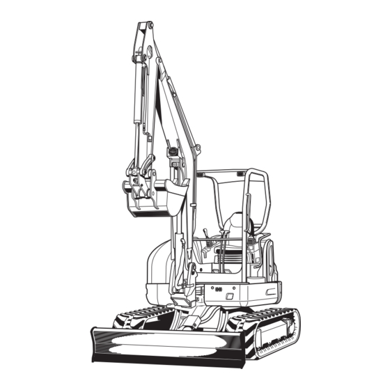
DESCRIPTION OF MACHINE PARTS DESCRIPTION OF MACHINE PARTS DEPICTED CONTENTS (1) Bucket cylinder (6) Swing bracket (11) Boom cylinder (16) Drive sprocket (2) Arm (7) Arm cylinder (12) Dozer cylinder (17) Track roller (3) Bucket link 2 and 3 (8) Canopy (13) Dozer blade (18) Front idler (4) Bucket link 1... -
Page 27: Instrument Panel And Control Elements
INSTRUMENT PANEL AND CONTROL ELEMENTS INSTRUMENT PANEL AND CONTROL ELEMENTS B Instrument Panel, Switch (1) LCD (3) Travel speed switch (5) Throttle potentiometer (7) Auto idle control switch (2) Horn switch (4) Starter switch (6) Light switch (8) One way hold switch Ref. - Page 28 INSTRUMENT PANEL AND CONTROL ELEMENTS B Control Pedals and Levers (1) Drive lever (left) (3) Boom swing pedal (5) Attachment control lever (right) (7) Drive pedal (left) (2) Attachment control lever (left) (4) Drive lever (right) (6) Dozer control lever (8) Drive pedal (right) Ref.
-
Page 29: Checks Before Start
Check the condition of the safety and warning labels. (See "DANGER, WARNING AND CAUTION LABELS" in "SAFE OPERATION" section.) Inspect ROPS / OPG (Top Guard Level I) for damage and if damage is found, contact your KUBOTA dealer for repair. (1) Starter switch (A) STOP... -
Page 30: Display Selector Switch
CHECKS BEFORE START BDisplay Selector Switch BLCD for Normal Operation Press the display selector switch while the engine is C Fuel gauge running. The LCD meter display will change from one indication mode to the other. Change the two-mode display according to your jobs. To avoid personal injury or death: A Before adding fuel, be sure to stop the engine. -
Page 31: Coolant Temperature Gauge
CHECKS BEFORE START C Fuel supply C Coolant Temperature Gauge The following functions are helpful when adding the fuel. The fueling progress can be monitored by a buzzer sound. Procedure To avoid personal injury or death: 1. Press the user setting switch(switch 1) or the display A Do not open the radiator cap during or just after selector switch(switch 5) on the meter with the key operation. -
Page 32: Hour Meter
CHECKS BEFORE START C Overheat warning C Hour-meter 1. If the coolant temperature becomes too high, the Indicates the total operating hours of the machine. message "Water temp is Rising" appears onscreen for a certain period of time. The LCD then gets back to How the indicator works normal, but the coolant temperature sensor marker "... -
Page 33: Warning Lamp
A If any warnings and problems are displayed, an alarm buzzer will beep. (See "LIST OF SCREENS" section for detail.) A Consult your local KUBOTA dealer from details concerning care and maintenance. (1) Charging lamp (1) Warning lamp (red, yellow) -
Page 34: Information Switch
CHECKS BEFORE START C Engine oil pressure low warning C Information When the engine oil pressure drops too low, the lamp (red) starts flashing and the following message appears in the display. Immediately stop the engine and check the engine oil level. -
Page 35: Setting The Clock
By pressing the switch 4, the year, month, day, hour and minute will be selected in this order. Select an item to readjust. A If you have any question, consult your local KUBOTA Dealer. BSetting the Clock 1. -
Page 36: Reordering The Year/Month/Day And Changing The Am/Pm System To The 24-Hour One
CHECKS BEFORE START [Status after setting the clock] BReordering the year/month/day and Changing the AM/PM System to the 24- hour One 1. On the user setting screen, select "Various Settings". (1) Switch 5 A Be careful not to accidentally press the switch 5 on the clock setting screen. -
Page 37: Log Record
CHECKS BEFORE START 3. Press the switch 5 and the following detailed screen 2. Press the switch 1 to make the menu appear shows up. onscreen. 3. Press the switch 2 and 3 to select the log record. Fix this choice with the switch (Switch 5). -
Page 38: Periodic Check
CHECKS BEFORE START BPeriodic Check BIf All the Check Points are not Displayed at a Glance on a Single Screen The following message appears on the LCD 10 hours before a periodic check. 1. Press the switch 4. 2. Each time the switch 2 or 3 is pressed, the check points scrolled up or down. - Page 39 CHECKS BEFORE START C Service hour meter When the hour meter reaches the hours circled in the maintenance list below, a message appears. The message shows up as follows. Hour meter indicator Check points Measures Intervals 1000 2000 every Engine oil (CF-4) 250 hrs change every...
-
Page 40: When The Check-Up Is Completed
CHECKS BEFORE START BWhen the Check-up is Completed BLight Switch When the check-up is completed, perform the following procedure to make the Periodic Check disappear from the When the starter switch is in position "RUN", the working screen. light(s) and CAB light(s) will be switched on by pressing 1. -
Page 41: Auto Idle Control Switch
CHECKS BEFORE START BAuto Idle Control Switch BTravel Speed Switch The switch is used to enable and disable the auto idle Travel speed will increase when this switch is pushed control. down. Switching the dual travel speed: A Enable: Press the auto idle control switch. When 1. -
Page 42: Cab Type Machines
CHECKS BEFORE START CAB TYPE MACHINES A The travel speed automatically changes into first speed (low speed) when the drive resistance BWiper/Washer Switch increases while traveling second speed (high speed). To engage the wiper, turn on the switch for the wiper when Thereafter, when the resistance decreases, it returns the starter key is in the "RUN"... -
Page 43: Opening/Closing Of Cab Door
CHECKS BEFORE START 2. Hold the grips tightly with both hands. Pull the grip slightly upward and toward yourself to let the BOpening/Closing of CAB Door windshield slide inward. 1. Unlock the CAB door and pull the knob. Open the CAB 3. -
Page 44: Air Conditioner
CHECKS BEFORE START AIR CONDITIONER BAir Flow Air in the CAB and fresh air introduced into the CAB flow as shown in the figure. Adjust the five air outlet ports to obtain the desired condition. (C) "FRESH AIR INLET" A Do not allow water to enter the fresh air port while washing the excavator. -
Page 45: Control Panel
CHECKS BEFORE START BControl Panel C Defrosting or demisting To defrost or demist the windshield, take the following steps. 1. Open the front air outlet and direct it to the windshield. 2. Set the blower switch and the temperature control dial the "3"... -
Page 46: Operation Of The Engine
OPERATION OF THE ENGINE OPERATION OF THE ENGINE Start the engine in the following manner: 1. Before starting the engine, make sure that all control levers are in the neutral positions. To avoid personal injury or death: A Read "SAFE OPERATION" at the beginning of this operator's manual. -
Page 47: Starting The Engine Under Cold Conditions
OPERATION OF THE ENGINE 4. Set the starter key to the "RUN" position. Hold the key A If you keep the pilot control lock lever at "UNLOCK" at this position until the " " mark on the display panel and try to start the engine, "Up Lever Lock" appears disappears. -
Page 48: Starting With An Auxiliary Battery
A The engine rpm's increases or decreases suddenly. A Sudden abnormal noises are heard. A Exhaust is black. A Warning lamp for engine oil lights up during operation. A In these cases, the excavator must be checked and serviced by your local the KUBOTA dealer. -
Page 49: Stopping The Engine
OPERATION OF THE ENGINE STOPPING THE ENGINE BPrecautions in case of Overheat To avoid personal injury or death: A Do not keep the bucket or dozer in an elevated To avoid personal injury or death: A Do not open the radiator cap during operation position, as a person could accidentally touch or just after shut-down. -
Page 50: Excavator Operation
EXCAVATOR OPERATION EXCAVATOR OPERATION RUNNING-IN OF THE NEW EXCAVATOR BAdjusting the Operator's Seat The operation and care of the new excavator influences its life span. Your new excavator has been carefully checked and tested before leaving the factory. In spite of this, all movable components must run-in during the first To avoid personal injury or death: 50 work hours. -
Page 51: Seat Belt
EXCAVATOR OPERATION BSeat Belt BPilot Control Lock Lever To avoid personal injury or death: To avoid personal injury or death: A Always use the seat belt with a ROPS/OPG (Top A To avoid injuries, check safety aspects all Guard Level I) protection structure. Adjust the around the excavator. -
Page 52: Driving
EXCAVATOR OPERATION DRIVING A Recommended technique for working on a slope. To avoid personal injury or death: A Before starting the engine, make sure that no one is near the excavator. A Before operating the excavator, check the track direction. (Front idler and dozer blade to the front of the excavator). -
Page 53: Drive Levers (Right,Left)
EXCAVATOR OPERATION TURNS 3. Activate the dozer control lever to raise the dozer. To avoid personal injury or death: A Do not change direction on steep slopes, or the excavator could tip over. A Before changing direction, beware of people in the work area. -
Page 54: Spin Turn
EXCAVATOR OPERATION 2. While travelling backward, bring the left drive lever into 2. Pull the left drive lever backward; the neutral position; the excavator will turn in the direction of the arrow of the excavator will turn in the direction of the arrow of the illustration below. -
Page 55: Up And Downhill Driving
While traveling uphill, keep the lower edge of the bucket approx. 20 to 40 cm above the ground. Although the KUBOTA excavator will not slip easily because of the tracks, it is safer to let the bucket slide over the ground while traveling downhill. -
Page 56: Two Pattern Selection System (Tpss)
EXCAVATOR OPERATION TWO PATTERN SELECTION SYSTEM (TPSS) To avoid personal injury or death: A Study control lever pattern A and pattern B. Then choose the one which is most familiar. A Position the pattern selector lever (located on the right side of operator's seat) in either the lower position (Pattern A) or the upper position (Pattern B). -
Page 57: Operation Of The Boom
EXCAVATOR OPERATION OPERATION OF THE BOOM OPERATION OF THE ARM To raise the boom, pull the attachment control lever back. Pull back the attachment control lever and the arm will be The boom is equipped with a cushion cylinder which helps pulled in. -
Page 58: Operation Of The Bucket
EXCAVATOR OPERATION OPERATION OF THE BUCKET BUnit Swing Operation To dig using the bucket, move the right attachment control 1. Move the control lever to the left and the upper lever from the neutral position, left. Moving the control structure will turn to the left. lever right, moves the bucket outwards and empties its 2. -
Page 59: Auxiliary Port Operation
EXCAVATOR OPERATION AUXILIARY PORT OPERATION The auxiliary port enable switch is used to operate hydraulic attachment such as hammers. BSelecting the Action Modes The AUX port has been factory-set to three action modes. You can select one of them. Up to five action modes can be preset. -
Page 60: Aux Port Handling Procedure
EXCAVATOR OPERATION C Checking the settings of each action mode When an action mode is selected and the " " mark BAUX Port Handling Procedure appears at the lower right of the icon, the flow volume 1. Turn the starter key to the "RUN" position. setting gets displayed by pressing the switch 4. - Page 61 EXCAVATOR OPERATION 3. Push the AUX port enable switch (switch 3). A Proportional control of the AUX port knob allows for slow-to-fast movement of attachment. Example; If you move the AUX port knob halfway, the attachment will move at approximately one-half speed. C One way hold Press the one way hold switch of the right attachment control lever, and the oil continues to flow through the...
-
Page 62: Setting The Maximum Flow Volume
EXCAVATOR OPERATION 3. Each time the switch 5 is pressed, the mode number changes. Select your desired setting mode number. BSetting the Maximum Flow Volume The AUX port has been factory-set to three action modes 1, 2 and 3. The action modes 4 and 5 can also be preset. C How to make the settings 1. - Page 63 EXCAVATOR OPERATION 5. Each time the switch 2 or 3 is pressed, the icon A There is no relationship between the icons and the changes. Select your desired icons. flow control settings. Select icons to suit the images of attachments to be connected. A In an action mode with the disable icon preset, such action mode is skipped even if selected.
- Page 64 EXCAVATOR OPERATION 6. Set the maximum flow volume for each AUX port. 7. Press the switch 2 or 3 to preset the maximum flow Press the switch 4 to move the setting cursor (arrow volume. mark) to the port 2 position of Thumb port at the right. Set the bar to the highest level, and the flow volume will be maximized.
- Page 65 EXCAVATOR OPERATION 8. Go back to Step 3 to make settings for the next action mode. When all the settings of all the action modes have been made, press the switch 1 to return to the normal screen. (1) Switch 1 C BUAUX port MAX.
- Page 66 EXCAVATOR OPERATION...
-
Page 67: How To Release Pressure Trapped In The Hydraulic System
EXCAVATOR OPERATION HOW TO RELEASE PRESSURE TRAPPED 3. Make sure that the flow volume in all the AUX ports is not minimized. IN THE HYDRAULIC SYSTEM If the pressure is removed after minimizing the flow volume in the AUX port, release pressure is not removed completely and the hose coupler may be unable to connect and disconnect. -
Page 68: 1-Way Or 2-Way Circuit Selection Valve Operation
EXCAVATOR OPERATION 1-way or 2-way CIRCUIT SELECTION 4. Move the AUX port knob mounted to the operating lever to the right to release pressure in the AUX port. VALVE OPERATION A selection valve which selects 1-way or 2-way circuit of service port has been installed on the hydraulic tank. -
Page 69: Auto Idle (Ai) Operation
EXCAVATOR OPERATION AUTO IDLE (AI) OPERATION 1. Throttle potentiometer To avoid personal injury or death: With this potentiometer the operator can adjust the A Stop the engine before removing/changing the engine speed when the auto idle control is activated. equipment. 2. -
Page 70: Important Information On Excavator Operation
EXCAVATOR OPERATION IMPORTANT INFORMATION ON A Relieve residual hydraulic pressure immediately after the engine has stopped. EXCAVATOR OPERATION A Do not try to crush concrete or boulders using side swings with the bucket. Also avoid using side sweeps of the bucket to move earth piles. A Under circumstances avoid... -
Page 71: Transporting The Excavator On A Vehicle
TRANSPORTING THE EXCAVATOR ON A VEHICLE TRANSPORTING THE EXCAVATOR ON A VEHICLE B Transporting on a Truck To avoid serious injury or death: A No directional changes should be made when the excavator is on the ramp. Should a change To avoid personal injury or death: of direction be necessary, drive off the ramp A After loading the machine on the truck, lower... -
Page 72: Towing The Machine
TRANSPORTING THE EXCAVATOR ON A VEHICLE 3. For additional safety, use blocks or supports under the ramps and the bed. (1) Chain (2) Block B Towing the machine 4. Completely align the ramps and the tracks and then drive the excavator slowly up the ramps. After ensuring that the tracks are completely on the bed, swing the upper body around to the back of the To avoid personal injury or death:... -
Page 73: Lifting Of The Excavator
LIFTING OF THE EXCAVATOR LIFTING OF THE EXCAVATOR (4) With the boom not swinging, set the swing pedal to the neutral position, place the pedal cover and stop the engine. To avoid serious injury or death: (5) Apply shackles (3200 kg or heavier-duty) through A The correct instructions for safe handling are the openings at both ends of the blade. - Page 74 LIFTING OF THE EXCAVATOR 2. Attaching the steel cables or straps. 4. Lifting (1) Always hook the excavator at three points. (one (1) Lift slowly and safely on the boom and left and right of the dozer) (2) Do not enter the excavator area when lifting. (2) Always use a shackle on each lifting hole when (3) Lift the excavator horizontally.
-
Page 75: Maintenance
MAINTENANCE MAINTENANCE MAINTENANCE INTERVALS Hour meter indicator Ref. Check points Measures Interval page check Daily check Coolant change every 2 years Fuel check Daily check check Daily check Engine oil change every 250 hrs check Daily check Hydraulic oil change every 1000 hrs Bucket and bucket Daily check... - Page 76 MAINTENANCE Hour meter indicator Ref. Check points Measures Interval page 1000 check Daily check Coolant change every 2 years Fuel check Daily check check Daily check Engine oil change every 250 hrs check Daily check Hydraulic oil change every 1000 hrs Bucket and bucket Daily check link pin...
- Page 77 *4 Consult your local KUBOTA dealer for this service. A The items listed above (@ marked) are registered as emission related critical parts by KUBOTA in the U.S.EPA non- road emission regulation. As the engine owner, you are responsible for the performance of the required...
-
Page 78: Opening And Closing Of Covers
MAINTENANCE OPENING AND CLOSING OF COVERS BOpening/Closing of the Side Cover BOpening/Closing of the Engine Hood 1. Open the engine hood first. 2. Raise the catch lever to unlock the side cover. 3. Push the side cover all the way forward, and it will be held by a stopper. -
Page 79: Where To Store The Tool
MAINTENANCE BWhere to store the Tool BWhere to store the Grease Gun [CANOPY type] [CANOPY type] The tool box is located under the seat. The grease gun is located under the seat. (1) Box for storage (1) Grease gun [CAB type] [CAB type] The tool box is located under the CAB door. -
Page 80: Daily Checks
MAINTENANCE DAILY CHECKS A Do not fill the recovery tank over the "FULL" marking. A Do not fill with dirty or salty water. To avoid personal injury or death: A When operating, keep hands and body inside BChecking Fuel Level of the ROPS / OPG (Top Guard Level I) protective envelope. -
Page 81: Checking Engine Oil Level
MAINTENANCE BChecking Engine Oil Level To avoid personal injury or death: A Stop the engine and remove the key before checking the oil level. A Use engine oil with the correct viscosity. (according to the outside temperature) A After stopping the engine and remove the key, wait 5 minutes, then check oil level. -
Page 82: Checking V-Belt
MAINTENANCE BChecking V-belt To avoid personal injury or death: A Stop the engine and remove the key before checking the V-belt. A Check the V-belt for cracks and proper tension. (See "Adjusting V-belt Tension" in "REGULAR CHECKS MAINTENANCE WORK" section.) BChecking Radiator and Oil Cooler (1) Radiator To avoid personal injury or death:... -
Page 83: Checking Washer Liquid
MAINTENANCE BChecking Washer Liquid BGreasing Front Attachments (without If the windows washer is switched on with the washer Bucket Pin and Boom Swing Fulcrum) liquid tank empty, the motor may be damaged. Always keep the tank filled. To avoid personal injury or death: A First lower all attachments on the ground then stop the engine and remove the key. -
Page 84: Greasing Bucket Pin
MAINTENANCE BGreasing Bucket Pin Grease the marked grease fittings shown by arrows in the illustration below. (1) Dozer cylinder boss (2) Dozer linkage pin BGreasing Boom Swing Fulcrum Grease the marked grease fittings shown by arrows in the illustration below. -
Page 85: Regular Checks And Maintenance Work
REGULAR CHECKS AND MAINTENANCE WORK REGULAR CHECKS AND MAINTENANCE WORK BDraining Water Separator [Checking and Draining] To avoid personal injury or death: A When operating, keep hands and body inside Water and dirt contained in fuel will settle down in the of the ROPS/OPG (Top Guard Level I) water separator. -
Page 86: Checking Battery Condition
REGULAR CHECKS AND MAINTENANCE WORK In case of non-refillable type, if the indicator turns BChecking Battery Condition white, do not quick charge the battery but replace it with new one. To avoid the possibility of a battery explosion: Mishandling the battery shortens the service life and adds For refillable type battery, follow the instructions to maintenance costs. -
Page 87: Greasing Swing Bearing Teeth
REGULAR CHECKS AND MAINTENANCE WORK C Battery Charging Battery Type Volts (V) Capacity GP24 (80D26R) 55 (at 5H.R(A.H)) To avoid personal injury or death: Reserve Cold Normal A When the battery is being activated, hydrogen Battery Type Capacity Cranking Charging and oxygen gases in the battery are extremely (min) Amps... -
Page 88: Every 200 Service Hours
REGULAR CHECKS AND MAINTENANCE WORK EVERY 200 SERVICE HOURS C Checking and adjustment of the fan belt tension 1. Press the fan belt in the middle, with a force of approx. Do all 50 and 100 hour servicing at the same time. 58.8 to 68.6 N (6 to 7 kgf). -
Page 89: Checking Radiator Hoses And Clamps
REGULAR CHECKS AND MAINTENANCE WORK BInspection and Cleaning Air Filter Element BChecking Radiator Hoses and Clamps Open the engine hood and remove the dust-cover. Take out only outer element, clean the element, case interior and reassemble. During reassembly, take care to install the dust-cover so that its TOP mark (arrow) faces up- To avoid personal injury or death: wards. -
Page 90: Air Filter Maintenance
REGULAR CHECKS AND MAINTENANCE WORK BAir Filter Maintenance BChecking Fuel Line and Intake Air Line 1. Check to see that all lines and hose clamps are tightened and not damaged. 2. If hoses and clamps are found worn or damaged, To avoid personal injury or death: replace or repair them at once. -
Page 91: Air Conditioner
REGULAR CHECKS AND MAINTENANCE WORK AIR CONDITIONER BCleaning Air Filter Open the cover and remove the filter cover, remove the air filter. (1) Filter (A) "AIR CONDITIONER AIRFLOW" A Pressure of compressed air must be under 205 kPa (2.1 kgf/ A If the filter is very dirty, replace the air filter. -
Page 92: Every 250 Service Hours
REGULAR CHECKS AND MAINTENANCE WORK EVERY 250 SERVICE HOURS 4. Let the engine idle for approx. 5 min. Check the engine oil level. To check the engine oil level, insert the Do all 50 hour servicing at the same time. engine oil dipstick completely into the respective port opening and pull out again. -
Page 93: Every 500 Service Hours
REGULAR CHECKS AND MAINTENANCE WORK EVERY 500 SERVICE HOURS BReplacing Fuel Filter Cartridge Do all 50, 100 and 250 hour servicing at the same time. BDrive unit Oil Change(First Oil Change of the 50 hours) To avoid personal injury or death: A Keep fire away. -
Page 94: Replacing Hydraulic Return Filter Element (First Replacement After 250 Service Hours)
A Always check the oil level when replacing the filter. BReplacing Breather Filter See "Replacing Hydraulic Return Filter Element" in (1) Bonnet left cover "EVERY 500 SERVICE HOURS" section. BReplacing Fan Belt Consult your local KUBOTA dealer for this service. (1) Head cover (2) Element (3) O-ring (4) Case... -
Page 95: Hydraulic Oil Change (Including Replacing Of The Suction Filter In The Hydraulic Tank)
REGULAR CHECKS AND MAINTENANCE WORK BHydraulic Oil Change (Including Replacing of the Suction Filter in the Hydraulic Tank) To avoid personal injury or death: A Wait long enough for the hydraulic fluid to cool down. Then begin with the change of the hydraulic fluid. -
Page 96: Hydraulic Oil Check With Hydraulic Hammers
BChecking Fuel Injection Nozzle (Injection Hammer Hrs. Hrs. work Pressure) every 300 every 150 portion Consult your local KUBOTA dealer for this service. Hrs. Hrs. every 200 every 100 EVERY 2000 SERVICE HOURS more Hrs. Hrs. Do all 50, 100, 200, 250, 500 and 1000 hour servicing at the same time. -
Page 97: Annual Servicing
A If swallowed, anti-freeze is poisonous to people, animals and birds. Replace air-conditioner pipes and hoses every two years. If the hoses or pipes are swollen, hard or cracked, they must be replaced earlier. (Consult your local KUBOTA Dealer for this service.) -
Page 98: Replacing Fuel Hoses And Hose Clamps
REGULAR CHECKS AND MAINTENANCE WORK Stop the engine, then remove the key and wait until it has cooled down completely. 1. Open the drain plug on the bottom of the radiator and drain coolant completely. Should a recovery tank be equipped, disconnect the line from the tank floor and then open the drain shutoff-valve. -
Page 99: Replacing Intake Air Line
Escaping refrigerant can cause severe injuries to eyes. A In contact with a flame, R134a refrigerant result in a toxic gas. A Do disconnect part refrigeration circuit of the air conditioning system. Consult your local KUBOTA Dealer for assistance and service. -
Page 100: Other Adjustments And Replacements
OTHER ADJUSTMENTS AND REPLACEMENTS OTHER ADJUSTMENTS AND REPLACEMENTS PURGING OF THE FUEL SYSTEM After adjustment is completed: Using the socket wrench, tighten the grease fitting. 1. Fill up the fuel tank with fuel. Tightening torque must be between 98 to 108 N-m. 2. -
Page 101: Special Information When Using Rubber Tracks
OTHER ADJUSTMENTS AND REPLACEMENTS A Make sure that no obstacles, such as stones are caught in the track. Remove such obstacles before To avoid serious injury or death: adjusting the track tension. A Do not work under the machine in this A Track seam condition. -
Page 102: Changing The Bucket
A Read the manual of the attachment to do a correct operation safely when other attachments are installed instead of KUBOTA specified bucket. (1) Fuse box BReplacing Fuses 1. Remove the cover of the fuse box. 2. Replace the burnt out fuse with a fuse having the same... -
Page 103: Fuse Capacities And Circuits
OTHER ADJUSTMENTS AND REPLACEMENTS BFuse Capacities and Circuits [CAB (Air-conditioner type)] A/C Controller (+B) Engine Stop [Canopy] Blower Motor Meter (+B) ECU (AC) ECU (+B) ECU (AC) ECU (+B) Relay Horn Switch Relay Horn Switch Alternator Horn Alternator Horn Lever Lock Work Light Lever Lock Work Light... -
Page 104: Auxiliary Electric
55W. 80A Alternator If you need another auxiliary electric, contact your 50A Main Power KUBOTA dealer for details. C Replacement procedure [80 Amp. Slow-blow fuse] 1. Disconnect the negative cord of the battery. 2. Remove the slow blow fuse case. -
Page 105: Troubleshooting
TROUBLESHOOTING TROUBLESHOOTING If the excavator does not show the desired performance, or when trouble arises, refer to the table below and undertake appropriate measures. Trouble Cause Countermeasure Pilot control lock lever in * Bring pilot control lock lever into "LOCKED" position. "UNLOCK"... - Page 106 TROUBLESHOOTING Trouble Cause Countermeasure Cylinder head gasket is * Replace. damaged (Coolant loss). Water Engine oil level too low * Fill to prescribed level. temperature Engine in red zone Maladjustment of fuel * Readjust ignition timing. (Overheating) injection Use of poor fuel * Use prescribed fuel.
-
Page 107: Operation Under Cold Weather Conditions
OPERATION UNDER COLD WEATHER CONDITIONS OPERATION UNDER COLD WEATHER CONDITIONS PREPARATION FOR OPERATION IN COLD PROCEDURE AFTER COMPLETING WEATHER WORK 1. Replace engine oil and hydraulic oil with those of Clean the excavator thoroughly after work and wipe dry. viscosities suitable for cold weather. Otherwise mud and earth on the tracks could freeze if the 2. -
Page 108: Long Storage
To ensure safety in operation, you are strongly requested to inspect and service the machine at regular intervals. For added safety, ask your KUBOTA dealer to replace the following important component parts periodically. These parts are prone to degradation in material or subject to wear and tear with time. It is difficult to judge how much they have been affected at regular inspection. - Page 109 Pipe boom - Selective valve Hydraulic hose (Swivel motor) Control valve - Swivel motor Control valve - Rotary joint Hydraulic hose (Travel motor) Rotary joint - Travel motor To prevent serious damage to the hydraulic system, use only a KUBOTA genuine hydraulic hose.
-
Page 110: Recommended Oils
RECOMMENDED OILS RECOMMENDED OILS 1. Before delivery the hydraulic oil used was Shell Tellus S2M46. 2. Use engine oil API service classification CF/CF-4 or better and SAE 10W-30. 3. Use SAE 90 (API, GL-4/GL-5) as drive unit oil for all seasons. 4. - Page 111 EGR with external EGR Models U35-4 C Fuel: A Cetane number of 45 is minimum. Cetane number greater than 50 is preferred, especially for temperatures below or elevations above 1500 m. A Diesel fuels specified to EN 590 or ASTM D975 are recommended.
-
Page 112: Appendices
APPENDICES APPENDICES MAIN DIMENSIONS U35-4 1700 4844 3397 3007 2013 3735 5281 U35-4 2470 [2480] 1695 5165 4745 1479 2222 *Dimensions in brackets: CANOPY type models A Above dimensions are based on the machine with unloaded digging bucket Q/C BUCKET. -
Page 113: Lifting Capacity
LIFTING CAPACITY LIFTING CAPACITY 1. The lifting capacities are based on ISO 10567 and do not exceed 75% of the static tilt load of the machine or 87% of the hydraulic lifting capacity of the machine. 2. The strokes are as follows. (1) The load point corresponds to the front bolt part of the arm. - Page 114 LIFTING CAPACITY...
- Page 115 LIFTING CAPACITY...
-
Page 116: List Of Screens
LIST OF SCREENS LIST OF SCREENS LIST OF NORMAL SCREENS Problem or failure Machine behavior Message Correction (What happened) (Provisional measure) Glow screen Wait until the glow mark This screen indicates that disappears. Then get the the glow lamp is on. engine started. -
Page 117: Navigation List Of Screens
LIST OF SCREENS NAVIGATION LIST OF SCREENS If an error occurs with the machine, one of the following messages appears in the LCD. In case of trouble, immediately contact your local dealer for inspection and repair. While the ( ) (information mark) appears onscreen, press the information switch, and detailed information will be displayed. - Page 118 LIST OF SCREENS Problem or failure Machine behavior Message Correction (What happened) (Provisional measure) Not equipped with overload warning This message appears if the function overload warning switch is pressed on machines not equipped with overload warning system. Out of fuel Fuel is running out.
- Page 119 LIST OF SCREENS Problem or failure Machine behavior Message Correction (What happened) (Provisional measure) Refill the radiator with coolant by the amount that Leave the engine idling until overflowed amount. Unclog Cool-down during this warning disappears. the radiator and other overheat idling Do not stop the engine components before use...
- Page 120 LIST OF SCREENS Problem or failure Machine behavior Message Correction (What happened) (Provisional measure) 12V short-circuit The majority of systems fail. * The engine may start and The sensor's or switch's 12V the machine may move. But Immediately contact your line is short-circuited.
Need help?
Do you have a question about the U35-4 and is the answer not in the manual?
Questions and answers
How do I start the trackhoe