
Related Manuals for Kubota U17-3a


Summary of Contents for Kubota U17-3a
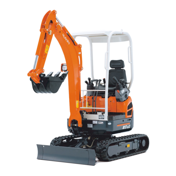
- Page 1 MINI EXCAVATOR MODEL U17-3α OPERATING INSTRUCTIONS 03/2012 W9232-8135-3 - Original -...
- Page 2 (page 12). This documentation does neither extend nor restrict the contractual warranty. KUBOTA Baumaschinen GmbH reserves its right to change the information contained in this document with respect to future technical development without altering the basic characteristics of the excavators described herein and without amending this document.
-
Page 3: Table Of Contents
Tables Table of contents Abbreviations ..............................7 General symbols ..............................8 GENERAL INFORMATION .........................9 Foreword................................9 EC declaration of conformity..........................10 Date of issue of the operating instructions .......................10 Operating personnel ............................10 Location of the operating instructions .......................11 Spare parts ...............................11 SAFETY RULES..........................12 Basic safety instructions ...........................12 Duties, liability and warranty ..........................12 Safety symbols..............................14 Approved use..............................15... - Page 4 Tables Description of the components of the right control console..............36 Displays and indicators – description ....................36 Left control console ............................. 37 Description of the components of the left control console ..............37 Controls ............................... 37 Description of the controls ........................38 Other machine components ........................
- Page 5 Tables Operating the arm...........................64 Operating the bucket ..........................64 Swivelling the swivel frame........................65 Swinging the boom ..........................66 Operating the auxiliary port..........................66 Return change-over valve ........................67 Placing out of operation ............................68 Operating the rotary beacon (accessories) ......................68 Operating the working lights ..........................69 Cold weather operation.............................69 Necessary preparations prior to the winter season ..................69 Operation during the winter season......................69...
- Page 6 Max. lifting load during swivel operation is 360° .................... 111 ACCESSORIES..........................115 KUBOTA rotary beacon..........................115 KUBOTA long arm............................115 KUBOTA pipe safety valve..........................115 Note on the usage..........................116 KUBOTA quick coupling systems and equipments..................116 KUBOTA bucket accessories ......................... 116...
-
Page 7: Abbreviations
Tables Abbreviations 1/min revolutions per minute International Organization for Standardi- percent zation ° degrees Kilogramme °C degree Celsius km/h Kilometre per hour Ampere Kilonewton acc. according Kilovolt American Petroleum Institute Kilowatt approx. approximately Litre ASTM American Society for Testing and L/min Litres per minute Materials... -
Page 8: General Symbols
Tables General symbols Warning light Swivel boom (left) Fuel display Swivel boom (right) Engine oil display Dozer up Charge display Dozer down Glow display Lever direction Hydraulic oil Control lever direction Travel speed Rotary beacon indicator on/off Low speed Display selector switch Forward travel Working light button Backward travel... -
Page 9: General Information
GENERAL INFORMATION Foreword These operating instructions apply only for the KUBOTA excavator model U17-3 which complies with the EC declaration of conformity as stated below (page 10). Safety instructions, the rules and regulations for the use of excavators given in these operating instructions apply to the excavators mentioned in this documentation. -
Page 10: Ec Declaration Of Conformity
General information EC declaration of conformity With the EC declaration of conformity, KUBOTA Baumaschinen GmbH certifies that the exca- vator is in conformity with the valid standards and regulations at the time of marketing. The CE conformity marking is located on the type plate and indicates compliance with the regulations. -
Page 11: Location Of The Operating Instructions
The compartment (1) for the operating instructions is under the operator's seat. Spare parts Genuine spare parts can be ordered from KUBOTA dealers by stating the model and the serial # of the excava- tor. The item numbers for the spare parts are indicated in the parts catalogue. -
Page 12: Safety Rules
Safety rules SAFETY RULES Basic safety instructions The EC machine utilization directive (2009/104/EC) dated 16/09/2009 applies for the operation of the aforementioned excavator. The information in these operating instructions applies for maintenance and repairs. National rules and regulations apply where applicable. Duties, liability and warranty A basic requisite for the safe handling and problem-free operation of the excavator is the knowledge of the safety instructions and safety regulations. - Page 13 Safety rules The owner must ensure at his own responsibility that the safety rules are observed (page 12), unapproved use and unauthorised operation (page 15) are excluded and the approved use (page 15) is ensured and the excavator is operated in accordance with the contractual conditions of use.
-
Page 14: Safety Symbols
Safety rules Safety symbols The following terms and hazard symbols are used in these operating instructions: Identifies important operating procedure information which may not be immediately evident to the operator. Identifies operating procedures which must be followed exactly to prevent damage to the excavator or other property. -
Page 15: Approved Use
Disposal must be undertaken in an appropriate way, according to legally prescribed pollution control and safety regulations. If you have questions about the correct disposal or storage of refuse and toxic waste, contact your KUBOTA dealer or a local waste management contractor. -
Page 16: Noise Emission And Vibration
Safety rules Noise emission and vibration The values specified in this manual have been identified in the test cycle at an identical machine and are valid for a standard equipment machine. The determined values are shown in the Specifications (page 32). Noise emission The noise levels were determined using the method of determining the guaranteed sound pressure level of ISO 4871 based on directive 2000/14/EC, appendix VI. -
Page 17: Safety Labels On The Excavator
Safety rules Safety labels on the excavator Keep the safety and warning symbols (labels) on the excavator clean and legible, replacing them if necessary. The positioning of the safety symbols is illustrated in the following figures. Code #: RD517-5789-0 (both sides) Code #: RD517-5788-0 Code #: RD517-5795-0 For information about loosening the crawler, consult the operating instructions. - Page 18 Safety rules Code #: RC418-5737-0 Keep away from fan and drive belt. Code #: TC030-4958-0 Do not touch hot parts, such as exhaust muffler, etc. Code #: RD517-5754-0...
- Page 19 Safety rules Code #: RA118-5776-0 Do not move the foot outside the front part of the boom swing pedal → risk of crushing. Code #: 69198-5784-0 Read the operating instructions and make sure you have understood the manual before starting or operating the excavator. Code #: RD517-5783-0 Code #: RB238-5736-0 For diesel fuel only! Keep away from fire.
- Page 20 Safety rules Code #: 69198-5722-0 (both sides) Do not enter the swivel area. Code #: RC108-5796-0 (both sides) Code #: RA011-5753-0...
- Page 21 Safety rules Code #: RG138-5717-0 When using a wider or deeper bucket take care when swinging or pulling in the front attachments that the bucket does not hit the canopy.
- Page 22 Safety rules Teile-Nr.: RA238-5744-0 U17-3...
-
Page 23: Safety Devices
Safety rules Safety devices Before starting the excavator, all safety devices must be installed properly and operational. No manipulation of safety devices, e.g. the shorting of limit switches, is allowed. Protective devices may only be removed after The excavator is standing still and the engine is stopped ... -
Page 24: Engine Stop Knob
Do not make any structural changes to the roll-over protection. At the time of damage, please contact your KUBOTA dealer. (Do not repair!) Never operate the excavator without the roll-over protection. Hazards coming from the hydraulic system If hydraulic oil gets into the eyes, rinse them immediately with clear water and subsequently seek medical aid. -
Page 25: Recovery, Loading And Transport
Recovery, loading and transport RECOVERY, LOADING AND TRANSPORT Safety rules for recovery For recovery of the excavator, a towing vehicle of at least the same weight class as the excavator must be used. A tow bar must be used for the recovery. If a tow rope is used, an additional vehicle to brake the excavator must also be attached. -
Page 26: Safety Rules For Transport
Recovery, loading and transport Safety rules for transport The ramps must have a sufficient load capacity for bearing the weight of the excavator. They must be placed securely on the transport vehicle and fastened. Support the loading area at the rear of the transport vehicle with sufficiently dimensioned supports. ... -
Page 27: Hoisting The Excavator With A Crane
Recovery, loading and transport Hoisting the excavator with a crane Adhere to the safety rules (page 12) and the safety rules for hoisting the excavator with a crane (page 25). Bring the excavator to the lifting position (see figure) on level ground. -
Page 28: Transport On A Flat Bed Trailer
Recovery, loading and transport As soon as the lifting gear is attached to the excavator, press cloths between lifting gear and excavator to protect the excavator. Always keep the machine level. Be sure that the centre line of the crane hook is aligned as exactly as possible with the centre line of the excavator and that the lifting angle is as specified. - Page 29 Recovery, loading and transport For protecting the vehicle, tie down the points as shown in the figure. For safe attachment, swing out the arm and bucket and lower the boom to the ground until the bucket linkage touches the loading area. ...
-
Page 30: Description Of The Excavator
Description of the excavator DESCRIPTION OF THE EXCAVATOR Model overview The excavator is only shipped as canopy version. Model U17-3... -
Page 31: Dimensions
Description of the excavator Dimensions For the dimensions of the U17-3, refer to the following figure and table. U17-3 Dimensions All dimensions in mm U17-3 990/ 990/ 3540 2440 2310 1910 1440 2750 3545 3840 3900 2340 2630 1240 1240 3610 2520... -
Page 32: Specifications
Description of the excavator Specifications Following are the specifications for these series. Specifications for the U17-3 KUBOTA Excavator Model name U17-3 Canopy Type (rubber crawler) Operating (without operator) 1650/1700* weight Volume m³ 0,04 Bucket Width Type 3 cylinder diesel engine, water-cooled... -
Page 33: Identification Of The Excavator
Description of the excavator Identification of the excavator The type plate of the excavator is located at the front of the swivel frame. The owner should enter the stamped data in the field on the back of the front cover. 1. -
Page 34: Assembly And Functions
Assembly and functions ASSEMBLY AND FUNCTIONS Component overview 1. Boom 10. Dozer cylinder 2. Arm cylinder 11. Dozer 3. Canopy 12. Swing block 4. Operator's seat 13. Dozer enlargement 5. Engine compartment cover 14. Boom cylinder 6. Drive sprocket 15. Bucket 7. -
Page 35: Operator's Place
Assembly and functions Operator's place The operator's place is located in the middle of the excavator. It includes the following control elements: 1. Left control console 2. Drive levers and control pedals 3. Right control console 4. Operator's seat Right control console The right control console (see figure) includes the following components: 1. -
Page 36: Description Of The Components Of The Right Control Console
Assembly and functions Description of the components of the right control console Right control lever The functions of the right control lever are described in the "Controls" section (page 37). Horn switch Depressing the horn switch activates the horn. Wrist rest The wrist rest allows fatigue-free operation of the control lever. -
Page 37: Left Control Console
Assembly and functions Left control console The left control console includes the following components: 1. Left control lever 2. Wrist rest 3. Control lever lock Description of the components of the left control console Left control lever The functions of the left control lever are described in the "Controls" section (page 37). Wrist rest The wrist rest allows fatigue-free operation of the control lever. -
Page 38: Description Of The Controls
Assembly and functions Description of the controls Control lever lock To mount and dismount the cab, the console must be raised by pulling up the control lever lock. The en- gine can only be started if the console is raised. The controls are only operational when the console is low- ered and the control lever lock is in the "down"... -
Page 39: Other Machine Components
Assembly and functions Other machine components The following details the other machine components. Fuse box The fuse box (1) is positioned inside the engine compartment on top of the coolant expansion reservoir. Battery The battery (1) is positioned at the left side of the machine be- hind the side cover. -
Page 40: Fuel Tank Filler Neck
Assembly and functions Fuel tank filler neck The fuel tank filler neck (1) is positioned under the fuel filler flap (2) at the front right side of the excavator. The fuel filler flap can be locked. -
Page 41: Engine Compartment
Assembly and functions Engine compartment The engine compartment (see figure below) is positioned at the rear of the swivel frame; it is covered by a lockable cover. 1. Main fuse 7. Fuel filter 2. Fuse box 8. Engine 3. Coolant expansion reservoir 9. -
Page 42: Hydraulic System
Assembly and functions Hydraulic system The controls, except the dozer control lever, the boom swing pedal, the auxiliary port pedal and the drive lev- ers, activate a pilot control circuit. The accumulator (figure below, position 1) allows the boom and arm to be lowered in case of an engine failure. The hydraulic oil tank contains the suction filter and the return filter. -
Page 43: Operation
Operation OPERATION Safety rules for operation The safety instructions (page 12) must be followed. The excavator may only be operated according to its approved use (page 15). The excavator may only be operated by trained personnel (page 10). ... -
Page 44: Guiding The Operator
Operation Guiding the operator If the operator's working and driving area is obscured, the operator must be supported by a guide. The guide must be capable of performing this kind of work. Before starting work, the guide and the operator must agree the necessary signals. ... -
Page 45: Initial Operation
Operation Initial operation Before initial operation, the excavator must first be checked visually for external transit damages and checked if the shipped equipment is complete as ordered. Check fluid levels as described in the "Maintenance" section (page 84). For a description of all operation features, see the "Operating the excavator"... -
Page 46: Operating The Excavator
Operation Operating the excavator For a safe excavator operation, see the following sections. Pre-operational services For the performance of the services, the excavator must be parked on level ground and the key must be removed. Also, the control levers and the swivel frame have to be locked (page 23). ... -
Page 47: Checking The Radiator And The Oil Cooler
Operation Checking the radiator and the oil cooler Open the left side cover (page 75). Check the radiator (2) and oil cooler (1) for leaks and debris (e.g. leaves). If there are leaves or other debris between the radiator and cooler, clean the radiator (page 90). -
Page 48: Checking The Oil Level Of The Hydraulic System
Operation Checking the oil level of the hydraulic system To determine the oil level exactly, do the following: Fully pull in the bucket and arm, lower the dozer to the ground, adjust the extendable track width to standard track width, align the front attachments with the swing mechanism in a straight line to the swivel frame and lower the boom to the ground. -
Page 49: Lubrication
Operation Lubrication Start the engine (page 53). Position the boom, arm, bucket and dozer as shown in the figure. Lock the control lever, stop the engine and remove the key. See the "Operating the controls during excavation work" section (page 61). ... - Page 50 Operation During the first 50 hours of operation, grease all grease nipples marked using "Anti-Seize" grease. Wipe emerged grease off immediately and store dirty cleaning cloths in the containers provided until their disposal.
-
Page 51: Checking The Fuel Level Of The Fuel Tank
Operation Checking the fuel level of the fuel tank Turn the starter switch (1) to the RUN position. Check the fuel level at the fuel gauge (2). If Fuel is shown in the display, there are only 2.0 L of fuel left in the fuel tank. ... -
Page 52: Horizontal Seat Adjustment (Seat Stand-Off)
Operation Horizontal seat adjustment (seat stand-off) Pull the horizontal seat adjustment lever (1) sideways and move the seat to the desired position by moving it forward or back, then release the lever. Check that the seat is locked into place. Spring adjustment (operator's weight) The seat can be set to the weight of the operator with the ad- justment grip (1). -
Page 53: Safety Instructions For Starting The Engine
Operation Safety instructions for starting the engine The excavator is equipped with an anti-theft system (page 76). When starting the excavator for the first time on a work day, carry out the pre-operational ser- vices (page 46). Make sure that there are no persons within the excavator's working area. It is essential to warn persons in the vicinity of the excavator by briefly honking the horn. - Page 54 Operation Insert the key (1) into the starter switch and turn it to the RUN position. The preglowing indicator (display below, position 3) comes on briefly. The engine can be started after it goes off. The engine oil pressure indicator (display below, position 1) lights up and goes off after the engine has started.
-
Page 55: Stopping The Engine
Operation Stopping the engine Make sure idle speed is set when stopping the engine. When stopping the engine with a higher speed, the turbocharger may get damaged due to insufficient lubrication. If the engine is to be stopped to take the excavator out of operation, the services for placing the excavator out of operation (page 68) must be carried out. -
Page 56: Driving The Excavator
Operation Also stop the engine immediately if the engine speed rises or drops suddenly, abnormal noises are heard, the excavating devices do not respond to the control lever as expected or the exhaust fumes are black or white. When the engine is still cold, white smoke for a short time is normal. Driving the excavator ... -
Page 57: Adjusting The Track Width
Operation Approach overhangs and edges of ditches carefully as they could cave in. Drive slowly downhill, do not allow the vehicle speed to increase uncontrollably. When driving, the bucket should be approx. 200 to 400 mm (A) over the ground (see figure). ... -
Page 58: Driving
Operation Using the dozer control lever (1), adjust the desired track width. To decrease the track width from 1240 to 990 mm, move the dozer control lever backward (figure, position ). To increase the track width from 990 to 1240 mm, move the dozer control lever forward (figure position ). -
Page 59: Turning
Operation To drive faster, press the travel speed button (1). An audible signal sounds and the indicator (2) comes up. Pressing the travel speed button again switches back to normal speed. Do not drive fast on muddy or uneven terrain, also if another control is operated (e.g. -
Page 60: Turning On The Spot
Operation Turning on the spot Do not make a turn on the spot with the travel speed button actuated. Move the drive levers in opposite directions. The tracks will turn in opposite directions. The centre of the vehicle is its vertical axis. -
Page 61: Notes For Rubber Crawler Operation
Operation Notes for rubber crawler operation Driving or turning on sharp objects or over steps causes excessive wear on the rubber crawlers and will lead to breaking of the rubber crawler or cause the crawler running surface and the steel inserts to be cut. ... -
Page 62: Notes For Using Wider And Deeper Buckets
Operation Never use the excavator as a crane, unless it is equipped with craning equipment (accessory). Adhering soil can be shaken off when the bucket is being emptied by moving the cylinder to the end of the stroke. Should this not suffice, swing out the arm as far as possible and operate the bucket back and forth. ... -
Page 63: Overview Of Control Lever Functions
Operation Overview of control lever functions The figure shows, in connection with the following table, the functions of the left and right control levers. Control levers Movement Right control lever Lower boom Raise boom Bucket crowd Bucket dump Left control lever Arm dump Arm crowd Swivel frame to the left... -
Page 64: Operating The Arm
Operation Operating the arm To dump the arm, push the left control lever forward (figure, position ). To crowd the arm, pull the left control lever back (figure, position ). The arm moves as shown in the figure. Operating the bucket ... -
Page 65: Swivelling The Swivel Frame
Operation The bucket moves as shown in the figure. Swivelling the swivel frame No person is allowed to stand in the swivel area during the movement. Swivel carefully to avoid any contact of the front attachments with adjacent objects. To turn anticlockwise, move the left control lever to the left (figure, position ... -
Page 66: Swinging The Boom
Operating the auxiliary port Implements are operated using the auxiliary port. Only implements approved by KUBOTA may be used. The implements must be operated in accordance with the operating instructions supplied with them. For auxiliary port specifications, see the "Specifications" section (page 32). -
Page 67: Return Change-Over Valve
Operation Depressing the right-hand part of the pedal (figure, position ) sends oil pressure to the connection (figure below, position 1). Depressing the left-hand part of the pedal (figure, position sends oil pressure to the connection (figure below, position 2). (1) Connection for right-hand part of pedal (2) Connection for left-hand part of pedal The auxiliary port can be secured against inadver-... -
Page 68: Placing Out Of Operation
Operation Placing out of operation Park the excavator in such a way that it can not move and is secured against unauthorised use. Drive the excavator on level ground. The machine should be parked under a roof. Fully pull in the bucket and arm, lower the dozer to the ground, adjust the extendable track width to standard track width, align the front attachments with the swing mecha- nism in straight line to the swivel frame and lower the boom... -
Page 69: Operating The Working Lights
Operation Operating the working lights The starter switch is in the RUN position. Press the working light button (1). Both the working lights and the instrument lighting are turned on. Press the button again to switch off. During work on public roads other road users must not be blinded. -
Page 70: Jump-Starting The Excavator
Operation Jump-starting the excavator Only a vehicle or starting device with a 12V power supply may be used. The operator must remain seated on the operator's place, the battery jumper cables must be connected by a second person. Make the battery accessible, and remove the positive terminal cover. ... -
Page 71: Emergency Stop Functions
Operation Emergency stop functions In case of emergency, you can switch off the engine and lower the boom manually. Manual engine stop If the engine cannot be stopped with the key, it can be stopped manually. You can only stop the engine with the ignition switch when the throttle lever is pushed back (idle speed). -
Page 72: Refuelling The Excavator
Operation Refuelling the excavator When refuelling the excavator, smoking, an open flame, or other sources of ignition are not al- lowed. The danger zone has to be clearly marked with signs. In the danger zone, there has to be a fire extinguisher. Spilled fuel must be bound immediately with an oil binding agent. -
Page 73: Replacing The Fuses
Operation Replacing the fuses Defective fuses may only be replaced with fuses of the same type and same rating. The bypassing of fuses, for example by a wire, is not allowed. If the malfunction can not be remedied by replacing the fuse, or if the fuse blows again when starting, contact skilled personnel. -
Page 74: Tilting The Operator's Seat
Operation Tilting the operator's seat Pull lever (1) forward and tilt the seat forward. When swing- ing the seat back, make sure the seat engages. Opening and closing the engine compartment cover Insert the key in the lock (1) of the engine compartment cover, turn it clockwise, then depress the lock. -
Page 75: Opening And Closing The Left Side Cover
Operation Opening and closing the left side cover Open the engine compartment cover (page 74). Remove the rubber mat and open the flap (1). Remove the wing nut (1). Open the left side cover (2). To close, shut the left side cover and tighten the wing nut, then refit the rubber mat. -
Page 76: Removing And Installing The Engine Compartment Cover Under The Operator's Seat
Operation Removing and installing the engine compartment cover under the operator's seat Tilt the operator's seat (page 74). Remove the fastening screws (1) and remove the engine compartment cover (2). To mount, attach the engine compartment cover and tighten the fastening screws. -
Page 77: Anti-Theft System
Operation Anti-theft system The excavator is equipped with an anti-theft system that restricts the engine to be started using a registered key only. If a registered key gets lost or stolen, you can invalidate it. This will prevent the engine from being started with this key, thus protecting the vehicle against theft. -
Page 78: The Key System
Use only the special KUBOTA key ring. Other key rings can lead to signal failures between the key and main key switch, and the engine can possibly not start or a key registration cannot be performed. -
Page 79: Registering A Black Key For The Machine
Operation If you attempt to register a fifth black key, the display will show the "Can't register any more" message. This means that the registration can not be done. Registering a black key for the machine Register a black key only under the following conditions: Make sure that there are no persons within the excavator's working area. - Page 80 Operation Do not turn the key at this point. If the key is in the RUN position, turn it back to the STOP position. The display shows the blinking "Register mode - insert key" message. After a brief moment, the display shows the "Finish - pull out black key"...
-
Page 81: Troubleshooting
Troubleshooting TROUBLESHOOTING The troubleshooting section includes only malfunctions and incorrect operations which must be remedied by the operator. Any other malfunctions may only be eliminated by trained personnel. The troubleshooting must be performed with the aid of the troubleshooting table. In order to locate a malfunction, first look in the MALFUNCTION column for the corresponding excavator malfunction. -
Page 82: Troubleshooting: Operation
(page 96). Suction filter restricted Change the suction filter in the hydraulic oil tank. Please contact your KUBOTA dealer. Travel speed button does not work Defective fuse in fuse box Replace the fuses (page 73). Horn and working light do not work Defective fuse in fuse box Replace the fuses (page 73). -
Page 83: Troubleshooting: Display Indications
Troubleshooting Troubleshooting: Display indications Preliminary Meas- Display Colour Problem/Error Solution No fuel. Yellow Refill. Engine may be Oil pressure too Stop the engine defective. Immedi- low. immediately. ately contact skilled personnel. Check the V-belt. Faulty battery When the V-belt is If the indicator does charger circuit. -
Page 84: Maintenance
A careful maintenance of the excavator will guarantee functional safety and longer service life. Neglect of the servicing will void the warranty and any liability by KUBOTA. Only use spare parts that are recommended by the manufacturer. Non-approved spare parts of inferior quality or wrong classification result in an increased risk of accidents. -
Page 85: General Maintenance Chart: 50 To 500 Hours Of Operation
Maintenance General maintenance chart: 50 to 500 hours of operation Operator servicing Elapsed hours of operation General maintenance Interval Page Checking the engine oil level daily Check hydraulic oil level daily Check fuel level daily Check coolant level daily Lubricate front-end attach- ... -
Page 86: General Maintenance Chart: 550 To 1000 Hours Of Operation
Maintenance General maintenance chart: 550 to 1000 hours of operation Operator servicing Elapsed hours of operation General maintenance 1000 Interval Page Checking the engine oil level daily Check hydraulic oil level daily Check fuel level daily Check coolant level daily Lubricate front-end attach-... -
Page 87: Servicing Maintenance Chart: 50 To 500 Hours Of Operation
Maintenance Servicing maintenance chart: 50 to 500 hours of operation Servicing by skilled personnel or KUBOTA dealer Elapsed hours of operation * Servicing Interval Page Check/adjust V-belt tension 250 h Check coolant hoses and 250 h clamps ... -
Page 88: Servicing Maintenance Chart: 550 To 1000 Hours Of Operation
Maintenance Servicing maintenance chart: 550 to 1000 hours of operation Servicing by skilled personnel or KUBOTA dealer Elapsed hours of operation Servicing 1000 Interval Page Check/adjust V-belt tension 250 h Check coolant hoses and 250 h clamps ... -
Page 89: Cleaning The Excavator
Maintenance Cleaning the excavator Before cleaning, shut down the engine and secure it against starting. If a steam cleaner is used for cleaning the excavator, do not direct the steam jet at electric com- ponents. Do not direct a water jet into the intake opening of the air filter. Do not clean the excavator with inflammable liquids. -
Page 90: Cleaning The Radiators
Maintenance Do not open the radiator cap while the engine is still hot, risk of scalding. Remove the radiator cap (1) by turning it anticlockwise. The coolant level should be at the lower mark of the filler plug; if not, add coolant. ... -
Page 91: Checking The Coolant Hoses
Maintenance Checking the coolant hoses Carry out the inspection while the engine is cold. Open the engine compartment cover (page 74). Open the engine compartment cover under the operator's seat (page 76). Check all hose connections to the engine, coolant expansion reservoir and the radiator for condition (cracks, bulges, hard spots) and firm seating of the clamps. -
Page 92: Replacing The Oil Filter
Maintenance Replacing the oil filter Place an oil drain pan under the oil filter and remove the oil filter (1) with a filter wrench by turning it anticlockwise. Coat the sealing ring of the new oil filter with engine oil. ... -
Page 93: Replacing The Coolant
Maintenance Replacing the coolant Drain the coolant only when the engine is cold. Total cooling system capacity: 2,7 L Open the engine compartment cover (page 74). Open the engine compartment cover under the operator's seat (page 76). Open the radiator cap (1). -
Page 94: Checking And Cleaning The Air Filter
Maintenance Checking and cleaning the air filter If the excavator is operated in a particularly dusty environment, the air filter must be checked more often. Open the engine compartment cover (page 74). Open the clips (3) and remove the cover (2). ... -
Page 95: Cleaning The Water Separator
Maintenance Manually screw in the new filter. Reset the cock vertically to the O position. Bleed the fuel system (page 72). Cleaning the water separator Open the engine compartment cover (page 74). Set the cock (3) horizontally to the C position. Place a cleaning cloth under the water separator to prevent fuel from spilling on the ground. -
Page 96: Replenishing Hydraulic Oil
Maintenance Replenishing hydraulic oil Pay attention to utmost cleanliness when servicing the hydraulic system. This service may only be carried out after the hydraulic oil has cooled down. Fully pull in the bucket and arm, lower the dozer to the ground, adjust the extendable track width to standard track width, align the front attachments with the swing mechanism in a straight line to the swivel frame and lower the boom to... -
Page 97: Servicing The Battery
Maintenance Servicing the battery Battery acid is very caustic. Avoid contact with battery acid under all circumstances. If clothing, skin or eyes have come in contact with battery acid, rinse the affected parts immediately with water. If the eyes are affected, immediately seek medical attention! Neutralise spilled battery acid immediately. -
Page 98: Charging The Battery
Maintenance Charging the battery Charge batteries only in sufficiently ventilated rooms. Smoking, uncovered lights or fire are not allowed in these rooms. Explosive gas is created when charging batteries. Open flames can cause an explosion. Remove the fill caps when charging batteries that are virtually empty. Leave the fill caps inside (not empty) batteries that are only charged for maintenance purposes, the fill caps can stay in the batteries. -
Page 99: Lubrication
Maintenance When replacing the battery, always install a battery of the same type with the same power rating and the same dimensions. Before installation, cover the battery terminals and cable clamps with petroleum jelly. Install the battery in the swivel frame and fasten it with the battery retainer. Check the battery for tightness. →... -
Page 100: Checking And Adjusting The Crawler Tension
Maintenance Checking and adjusting the crawler tension If the crawlers are too tight, wear is increased. If the crawlers are too loose, wear is increased and the crawlers may come off. When parking an excavator with rubber crawlers, ensure that the seam (∞) is on top half way between the two sliders. -
Page 101: Adjusting The Crawler Tension
Maintenance Adjusting the crawler tension Tightening the crawlers Position the grease gun on the grease nipple (1). Pump the grease gun until the specified crawler tension is obtained. Loosening the crawlers Cautiously unscrew the pressure valve (figure above, position 2) and loosen the crawler. Grease could squirt out from the cylinder opening. -
Page 102: Greasing The Pilot Valve Linkage
Maintenance Greasing the pilot valve linkage Pull up the rubber boot on the control lever (3). Lubricate the u-joint (1) below the plate (2) with grease. See the "Recommended lubricants" section (page 105). Insert the rubber boot in the console. ... -
Page 103: Checking The Bolted Joints
Maintenance Checking the bolted joints The table below contains the torques for nuts and bolts. These may only be tightened with a torque wrench. Missing torques can be requested from KUBOTA. Tightening torque for screws Nm (kgf•m) 4 T (4.6) 7 T (8.8) -
Page 104: Tightening Torque For Hydraulic Pipes
Maintenance Tightening torque for hydraulic pipes Wrench size Torque in Nm Pipe size Thread 30-35 M12x1.5 30-35 M14x1.5 40-45 10x1.5 M16x1.5 60-65 12x1.5 M18x1.5 75-80 15x1.5 M22x1.5 90-100 16x2 M24x1.5 110-120 18x2 M26x1.5 130-140 22x2 M30x2 140-160 25x2.5 M36x2 M22x1.5 60-65 15x1.5 for ED-2 only... -
Page 105: Recommended Lubricants
The excavator is shipped with ESSO NUTO H46 hydraulic oil. If bio oil is used, please contact your KUBOTA dealer. Use only API CF or API CI-4 grade engine oil. Do not use different grades, such as CF-4, CG-4 or CH-4. -
Page 106: Excavator Repairs
Maintenance Excavator repairs Repairs on the excavator may only be carried out by trained personnel. If repairs are carried out on supporting parts, for example welding on frame parts, the work must be checked by an expert. After repairs the excavator may only be taken into operation if its proper operation has been determined. For this check particular attention must be paid to the repaired parts and the safety devices. -
Page 107: Safety Inspection
Safety inspection SAFETY INSPECTION All safety inspections are based on the national worker's protection regulations, safety regulations and technical specifications applicable to the country where the machine is deployed. The operator (page 15) should arrange for the safety inspections to be performed at specified intervals accord- ing to national rules and regulations. -
Page 108: Taking Out Of Service And Storage
Taking out of service and storage TAKING OUT OF SERVICE AND STORAGE If the excavator is taken out of service for up to six months, the measures before, during and after taking out of service must be carried out as described below. If the vehicle is to be taken out of service for a period of over six months, contact the manufacturer for additional measures. -
Page 109: Start-Up After Taking Out Of Service
Taking out of service and storage Start-up after taking out of service If necessary, clean the excavator thoroughly. Check the hydraulic oil for condensate water, replacing the oil if necessary. Install the battery (page 98). Check the safety devices for proper operation. ... -
Page 110: Lifting Capacity Of The Excavator
Lifting capacity of the excavator LIFTING CAPACITY OF THE EXCAVATOR The lifting capacity of the excavator is based on ISO 10567 and does not exceed 75% of the static tipping load or 87% of the hydraulic lifting capacity of the machine. ... -
Page 111: Max. Lifting Load During Swivel Operation Is 360
Lifting capacity of the excavator Max. lifting load during swivel operation is 360° Standard arm vs. long arm l... - Page 112 Lifting capacity of the excavator Lifting capacity over front end, dozer blade down MODEL U17-3 SPECIFICATION CANOPY VERSION WITH RUBBER CRAWLER Standard ARM kN (t) LOAD RADIUS (mm) Height Mini- Maxi- [mm] 1500 2000 2500 3000 4500 4000 3500 3000 2500 (0.31) 2000...
- Page 113 Lifting capacity of the excavator Lifting capacity over side (track width 1240 mm) MODEL U17-3 SPECIFICATION CANOPY VERSION WITH RUBBER CRAWLER Standard ARM kN (t) LOAD RADIUS (mm) Height Mini- Maxi- [mm] 1500 2000 2500 3000 4500 4000 3500 3000 2500 (0.23) 2000...
- Page 114 Lifting capacity of the excavator Lifting capacity over front end, dozer blade up MODEL U17-3 SPECIFICATION CANOPY VERSION WITH RUBBER CRAWLER Long ARM kN (t) LOAD RADIUS (mm) Height Mini- Maxi- [mm] 1500 2000 2500 3000 4500 4000 3500 3000 (0.24) 2500 (0.24)
-
Page 115: Accessories
The accessories approved for this excavator by the respective countries are described in the following seg- ments. For further accessories, please contact your KUBOTA dealer or authorized retailer. Accessories from other manufacturers may only be fitted after prior written approval from KUBOTA. -
Page 116: Note On The Usage
It is designed to receive KUBOTA bucket accessories only. The related operating instructions are attached to the excavator's operating instructions. For further information, please contact your KUBOTA dealer or authorized retailer. KUBOTA bucket accessories For further bucket accessories, please contact your KUBOTA dealer or authorized retailer. - Page 117 Accessories...
Need help?
Do you have a question about the U17-3a and is the answer not in the manual?
Questions and answers