Sign In
Upload
Download
Table of Contents
Contents
Add to my manuals
Delete from my manuals
Share
URL of this page:
HTML Link:
Bookmark this page
Add
Manual will be automatically added to "My Manuals"
Print this page
×
Bookmark added
×
Added to my manuals
Manuals
Brands
Riello Manuals
Thermostat
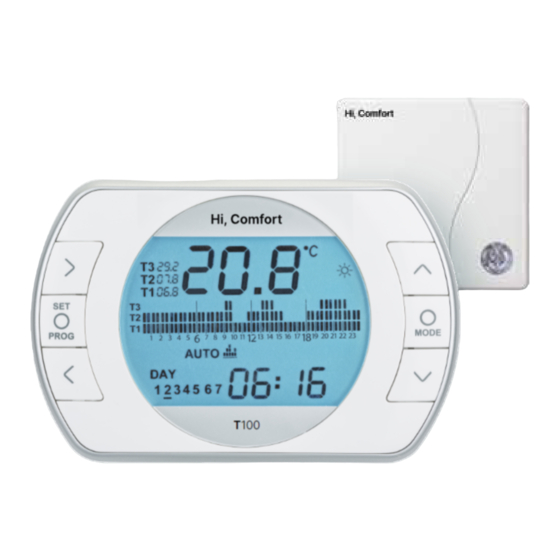
Hi, Comfort 100
Installer and user manual
Riello Hi, Comfort 100 Installer And User Manual
Hide thumbs
1
2
Table Of Contents
3
4
5
6
7
8
9
10
11
12
13
14
15
16
17
18
19
20
21
22
23
24
25
26
27
28
29
30
31
32
33
34
35
36
37
38
39
40
41
42
43
44
45
46
47
48
49
50
51
52
53
54
55
56
57
58
59
60
61
62
63
64
65
66
67
68
69
70
71
72
73
74
75
76
77
78
79
80
81
82
83
84
page
of
84
Go
/
84
Contents
Table of Contents
Bookmarks
Table of Contents
Table of Contents
General Information
General Notices
What Is the Hi, Comfort T100 for
Modes of Use
Glossary of Technical Terms
Hi, Comfort T100 Control Class Declaration, According to the Erp Directive
Installation
Contents of the Package
Practical Installation Diagrams
Technical Data
Dimensions
Three-Phase Installation
Commissioning
User Interface
Display
Setting the Date and Time
Setting the Heating/Cooling Mode
Setting the Operating Mode
Setting the Extra Functions
Setting the Heating/Cooling Time Program in Automatic Operating Mode
Setting the DHW Time Program
Setting the Heating/Cooling Room Setpoint Temperature
Setting the DHW Setpoint Temperature
Displaying Operating Information
Technical Menu - Advanced Programming
RF Receiver Configuration
3.14 Linking Function
3.15 Resetting the Wifi Box
Alarms and Operating Statuses
LED Notification Lights for the Wifi Box and Boiler RF Receiver
Boiler and Hi, Comfort T100 Alarms
Advertisement
Quick Links
1
Table of Contents
2
Modes of Use
3
User Interface
4
Setting the Heating/Cooling Mode
5
3.14 Linking Function
6
3.15 Resetting the Wifi Box
Download this manual
Hi, Comfort 100
EN
INSTALLER AND USER MANUAL
Table of
Contents
Previous
Page
Next
Page
1
2
3
4
5
Advertisement
Table of Contents
Need help?
Do you have a question about the Hi, Comfort 100 and is the answer not in the manual?
Ask a question
Questions and answers
Related Manuals for Riello Hi, Comfort 100
Thermostat Riello Hi, Comfort T100 Installer And User Manual
(376 pages)
Thermostat Riello RiCLOUD Quick Start Manual
(20 pages)
Thermostat Riello ricloud Quick Start Manual
(25 pages)
Thermostat Riello RiCLOUD NA Series Quick Start Manual
(17 pages)
Thermostat Riello BeSMART Installer And User Manual
Wifi box and boiler rf receiver (80 pages)
Thermostat Riello Hi, Comfort T300 User Manual
(88 pages)
Thermostat Riello CDI 15 Quick Start Manual
Control card for helioterm inverter remote connection (8 pages)
Thermostat Riello BeSMART Quick Start Manual
Wifi (9 pages)
Thermostat Riello Hi, Comfort T200 Instruction Manual
(16 pages)
Thermostat Riello BeSMART Quick Start Manual
(8 pages)
This manual is also suitable for:
Hi, comfort t100 wi-fi
Hi, comfort g100-w
Hi, comfort g100-r
Table of Contents
Save PDF
Print
Rename the bookmark
Delete bookmark?
Delete from my manuals?
Login
Sign In
OR
Sign in with Facebook
Sign in with Google
Upload manual
Upload from disk
Upload from URL


Need help?
Do you have a question about the Hi, Comfort 100 and is the answer not in the manual?
Questions and answers