
Related Manuals for Riello BeSMART


Summary of Contents for Riello BeSMART
- Page 1 Installer and User Manual BeSMART Thermostat | WiFi Box and boiler RF receiver Installer and User Manual...
- Page 2 Dear Customer, Thank you for choosing the BeSMART control. This control device for heating (and cooling) systems and boilers is easily installed and, if used correctly, offers better quality comfort as well as energy savings. This thermostat has been designed to support a maximum of 2 A at 30 VDC or 0.25 A at 230 VAC (specifications for internal relay to switch the boiler...
-
Page 3: Table Of Contents
3.2 Display ....46 1.2 What is the BeSMART for? ..5 3.3 Setting the date and time ..47 1.3 Modes of use . -
Page 4: General Information
The BeSMART is powered by 2 x AA batteries. The BeSMART must be kept away from sources of heat or air currents as these may affect the accuracy of the readings from the incorporated room sensor. -
Page 5: What Is The Besmart For
BeSMART (mul- ti-zone management). If the BeSMART is installed together with the WiFi Box and you have a WiFi internet connection in your home, the BeSMART system allows you to carry out... -
Page 6: Modes Of Use
Domestic hot water: the water heated by the boiler which is dispensed from the domestic taps. Fault code: this code shows on the display to flag any boiler or BeSMART faults. Original set-up: this is the control panel configuration after turning on the device for the first time or after a reset. - Page 7 Connection via OTBus communication bus: this is a communication mode between the BeSMART and the boiler, where a series of information is ex- changed between the two electronic systems. This proprietary connection can be used as opposed to the simple ON/OFF (open/closed contact) and is set by the boiler manufacturer specifically for the BeSMART.
-
Page 8: Besmart Control Class Declaration, According To The Erp Directive
The BeSMART ON/OFF contact always maintains the same technical char- acteristics (BeSMART relay, WiFi Box relay, boiler RF receiver relay) wherev- er it is positioned and these must be respected when connecting the relay and the components it controls via cable. NOTE: Never exceed the maximum electrical loads. - Page 9 BeSMART configuration characteristics contribution Boiler with Connection via communication bus to the variable delivery BeSMART. Delivery temperature to the temperature boiler calculated on the basis of at least VIII = 5% (controlled by 3 distinct room temperatures. At least 3...
-
Page 10: Installation
INSTALLATION Contents of the package The WiFi BeSMART package contains the following components: Component Description BeSMART = boiler remote control with room programmable thermostat function (*) or room programmable thermostat (**). (*) where there is an active OTBus connection in one of the... - Page 11 OTBus connector (only for boilers without one) for an OTBus connection between the WiFi Box and the boiler or the boiler RF receivers (optional) and the boiler or the BeSMART and the boiler. It can also be used to connect the external probe (optional).
- Page 12 The WiFi Box kit contains the following components: Component Description WIFI Box USB power adapter USB cable A – USB Mini B = WiFi Box power cable USB cable A = cable connecting the WiFi Box and the boiler Quick guide Installer/User Manual If installing additional BeSMARTs or boiler RF receivers, you must follow the procedure to link them to the WiFi Box (see "3.14 Linking function"...
- Page 13 The Boiler RF receiver kit contains the following components: Boiler RF receiver Component Description Boiler RF receiver Quick guide If installing additional BeSMARTs or boiler RF receivers, you must follow the procedure to link them to the WiFi Box (see "3.14 Linking function" to page 72).
-
Page 14: Practical Installation Diagrams
Room thermostat connection, dry contact ON/OFF (max 0.25 A @ 230 V) OTBus protocol connection, contact for proprietary communication protocol Zone valve without limit switch Zone valve with limit switch 2.2.1 Diagram 1 ON/OFF programmable thermostat for heating (TA). Single heating zone in ON/OFF mode. BeSMART PROG MODE RESET... -
Page 15: Diagram 2
2.2.2 Diagram 2 ON/OFF programmable thermostat for heating (TA). Multi-zone heating in ON/OFF mode. BeSMART BeSMART BeSMART PROG MODE PROG MODE PROG MODE RESET RESET RESET zona 1 zona ... zona ... Up to 8 areas if WiFi Box is available. -
Page 16: Diagram 4
Single zone in modulating thermoregulation mode. OT: full control of boiler, heating, DHW, alarms and settings. Multi-zone heating in ON/OFF mode. Set the boiler to “zone valve” mode. Request procedure from Technical Assistance Centre. BeSMART BeSMART BeSMART PROG MODE PROG... -
Page 17: Diagram 5
2.2.5 Diagram 5 ON/OFF programmable thermostat for heating (TA). Single heating zone in ON/OFF mode. Wireless installation. Only one BeSMART can be connected to the boiler RF receiver. Boiler RF receiver BeSMART PROG MODE RESET 230 V 2.2.6 Diagram 6 Modulating programmable thermostat/remote control. -
Page 18: Diagram 7
2.2.7 Diagram 7 ON/OFF programmable thermostat for heating (TA) with remote control via WiFi. Single heating zone in ON/OFF mode. BeSMART WiFi Box PROG MODE WiFi WiFi RESET BeSMART internet server 230 V... -
Page 19: Diagram 8
2.2.8 Diagram 8 Modulating programmable thermostat/remote control with remote con- trol via WiFi. Single heating zone in modulating thermoregulation mode. OT: full control of boiler, heating, DHW, alarms and settings. BeSMART WiFi Box PROG MODE WiFi WiFi RESET BeSMART internet... -
Page 20: Diagram 9
2.2.9 Diagram 9 ON/OFF programmable thermostat for heating (TA) with remote control via WiFi. Wireless installation. WiFi Box WiFi WiFi BeSMART internet server BeSMART 230 V PROG MODE RESET 2.2.10 Diagram 10 Modulating programmable thermostat/remote control, , with remote con- trol via WiFi. -
Page 21: Diagram 11
Wireless installation. To extend the WiFi signal it is possible to use the WiFi EXTENDER accessory in alternative to the Boiler RF Receiver Boiler RF receiver WiFi Box WiFi WiFi BeSMART internet server 230 V 230 V BeSMART PROG MODE... -
Page 22: Diagram 12
Wireless installation. To extend the WiFi signal it is possible to use the WiFi EXTENDER accessory in alternative to the Boiler RF Receiver Boiler RF receiver WiFi Box WiFi WiFi BeSMART internet server 230 V 230 V BeSMART PROG MODE... -
Page 23: Diagram 13
2.2.13 Diagram 13 ON/OFF programmable thermostat for heating (TA) with remote control via WiFi. Multi-zone heating in ON/OFF mode. WiFi Box WiFi WiFi BeSMART internet server 230 V BeSMART BeSMART BeSMART PROG MODE PROG MODE PROG MODE RESET RESET RESET zona 1 zona ... -
Page 24: Diagram 14
Thermoregulation for every zone with automatic selection of the maxi- mum request temperature between the different zones. Set the boiler to “zone valve” mode. Chiedere procedura a Cen- tro Tecnico di Assistenza. WiFi Box WiFi WiFi BeSMART internet server 230 V BeSMART BeSMART BeSMART... -
Page 25: Diagram 15
Boiler RF Receiver Set the boiler to “zone valve” mode. Chiedere procedura a Cen- tro Tecnico di Assistenza. Boiler RF receiver WiFi Box WiFi WiFi BeSMART internet server 230 V 230 V BeSMART BeSMART BeSMART... -
Page 26: Diagram 16
2.2.16 Diagram 16 Wireless management of the zone valves via RF zone receiver. Generic use both in system ON/OFF mode and in OT mode, with or with- out WiFi. BeSMART BeSMART BeSMART PROG PROG PROG MODE MODE MODE RESET RESET... -
Page 27: Diagram 17
2.2.17 Diagram 17 Wireless management of various devices controlled by just one BeSMART and of zone valves via RF zone receiver. BeSMART PROG MODE RESET RF zone RF zone RF zone receiver receiver receiver 230 V 230 V 230 V zona 1 zona ... -
Page 28: Diagram 18
OT: full control of boiler, heating, DHW, alarms and settings. Thermoregulation for every zone with automatic selection of the maxi- mum request temperature between the different zones. Multi-zone heating in ON/OFF mode. WiFi Box WiFi WiFi BeSMART internet server 230 V BeSMART BeSMART BeSMART... -
Page 29: Diagram 19
Multi-zone heating in ON/OFF mode. To extend the WiFi signal it is possible to use the WiFi EXTENDER accessory in alternative to the Boiler RF Receiver. Boiler RF receiver WiFi Box WiFi WiFi BeSMART internet server 230 V 230 V BeSMART BeSMART... -
Page 30: Diagram 20
Multi-zone heating system in modulating thermoregulation mode. OT: full control of boiler, heating, DHW, alarms and settings. Thermoregulation for every zone with automatic selection of the maximum request temperature between the different zones. WiFi Box WiFi WiFi BeSMART internet server 230 V BeSMART BeSMART BeSMART... -
Page 31: Diagram 21
To extend the WiFi signal it is possible to use the WiFi EXTEN- DER accessory in alternative to the Boiler RF Receiver Boiler RF receiver WiFi Box WiFi WiFi BeSMART internet server 230 V 230 V BeSMART BeSMART BeSMART... -
Page 32: Diagram 22
OT: full control of boiler, heating, DHW, alarms and settings. Thermoregulation for every zone with automatic selection of the maximum request temperature between the different zones. Multi-zone heating in ON/OFF mode. WiFi Box WiFi WiFi BeSMART internet server 230 V BeSMART BeSMART BeSMART... -
Page 33: Diagram 23
Multi-zone heating in ON/OFF mode. To extend the WiFi signal it is possible to use the WiFi EXTEN- DER accessory in alternative to the Boiler RF Receiver. Boiler RF receiver WiFi Box WiFi WiFi BeSMART internet server 230 V 230 V BeSMART BeSMART... -
Page 34: Technical Data
Linking function" to page 72). When installing one or more boiler RF Receivers connected to one or more BeSMART it is necessary to perform the connecting procedure to the BeSMART thermostat (see "3.14 Linking function" to page 72). Technical Data Thermostat... - Page 35 16.95 Maximum consumption Maximum length of WiFi Box cables – boiler connection via cables Minimum operating room temperature °C WiFi signal percentage to guarantee correct BeSMART system operation Description Boiler RF receiver Units Input 100-240 / 0,1 VAC/A Transformer power...
-
Page 36: Dimensions
Dimensions Units W - Width H - Height D - Depth PROG MODE RESET... -
Page 37: Three-Phase Installation
PROG MODE PROG MODE RESET RESET Fix the BeSMART base to the wall or electrical box using the screws provided. Using screws other than those PRO- VIDED may compromise the correct closure of the plastic. Make sure that the screw head is correctly inserted in the hole. - Page 38 The BeSMART can be installed in one of the following ways: Wireless No wiring is required. Please check the maximum open- field distances shown BeSMART thermostat technical data. ON/OFF Loss of radio frequency communi- cation is flagged with alarm E82.
- Page 39 "2.3 Technical Data" to page 34) which replicates the BeSMART ther- mostat relays linked to it. It is ON if at least 1 of the BeSMART relays is Insert the 2 x AA batteries provided, ON, and OFF if all of the BeSMART with correct polarity.
- Page 40 The position and distinction between The USB cable to connect the de- the 2 outputs on the USB plug are vice to the boiler has an end with 4 given below. terminals. Black TA Black TA 230 V Red OT Red OT Never 230 V...
- Page 41 (it is recommended that you brown consult the boiler installer manual). blue In the case of BeSMART ther- 230 V mostats wired in ON/OFF mode, black or zone valve microswitches, it is recommended that you con-...
- Page 42 WiFi Box OUTPUTS/BOILER output; Resetting the OTBus connection auto-configuration function The BeSMART is configured to function in ON/OFF mode. Should it be connected to an OTBus communication bus (wired or wire- less/radio frequency), the BeSMART auto-configures to the “Boiler remote...
- Page 43 Installing and configuring the Match the WiFi ID of the WiFi Box to the user account. smartphone APP If you need to link other thermostats Download the APP on your smart- and/or boiler RF receivers to the phone or tablet; WiFi Box via radio frequency, press the clear button on the WiFi Box for 5 seconds until the LEDs flash at the...
- Page 44 4 minutes to auto-configure. Once online, system requires up to 4 minutes to auto-configure. Restart the WiFi router at the end of the operation. NOTE For further information, please see the BeSMART APP manual.
-
Page 45: Commissioning
COMMISSIONING User interface PROG MODE RESET BACK button = allows you to select the desired field, reset an alarm or activate the ONE HOUR BOOSTER function SET/PROG button = allows you to access the menus or selected field and save FORWARD button = allows you to select the desired field or activate the special ADVANCE function UP button = increases the field selected or displays the room tempera-... -
Page 46: Display
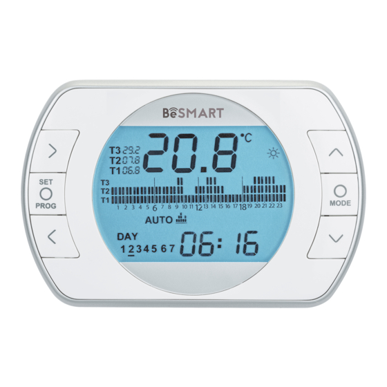
Room temperature read by the BeSMART thermostat Flame detection (available with OTBus connection between the WiFi Box and the boiler or the RF receiver and the boiler or the BeSMART and the boiler, if provided for by the OTBus protocol) or heating request if the BeSMART system is in ON/OFF mode Unit of measure (°C/°F) -
Page 47: Setting The Date And Time
Setting the date and time When month is selected, the corre- sponding number flashes and the From the HOME screen, press the message Non is displayed. SET/PROGRAM button twice. PROG PROG RESET RESET When year is selected, the corre- Select the desired field (hours, min- sponding number flashes and the utes or day) using the FORWARD message YEA is displayed. -
Page 48: Setting The Heating/Cooling
Setting the heating/ Press the SET/PROG button to set. cooling mode The BeSMART is default set to heat- ing mode. In heating mode, the BeSMART ac- tivates a request for heat when the PROG room temperature is below the set temperature. -
Page 49: Mode
If at least one BeSMART ther- mostat is in cooling mode, the heating request via OTBus is not considered. Setting the operating mode From the HOME screen, press ESC/ RESET MODE repeatedly 3.5.2 SUMMER/DHW mode BeSMART in SUMMER/DOMESTIC HOT WATER mode. In this mode, the boiler provides domestic hot water where requested (instant boiler). - Page 50 BeSMART thermostats con- nected via OTBus, if one of In Winter/AUTOMATIC mode, the these devices is in cooling BeSMART follows the time program mode, the heating request to set in the user-programming menu the boiler is not considered. for heating.
-
Page 51: Setting The Extra Functions
Setting the extra 3.5.6 WINTER/PARTY mode functions In PARTY mode, the BeSMART 3.6.1 ADVANCE function for takes the T3 room setpoint temper- AUTOMATIC operating mode ature (comfort), ignoring the heating time program, until midnight of the current day, and then automatical-... - Page 52 UP buttons for Box and the boiler or the RF receiver 5 seconds simultaneously to display and the boiler or the BeSMART and the request for password entry. the boiler, if provided for by the OT- Bus protocol). If the rIE alarm is quick flash (0,5 sec.) on the HOME screen in the...
-
Page 53: Mode
If the password has already been If the password entry is incorrect, set, "00" is displayed; enter the pas- the text "LOC" is displayed for 5 sword using the UP and DOWN seconds in place of the ambient buttons and press SET to con- temperature, and the functions of all firm. - Page 54 Press the SET/PROG button to set. Wednesday PROG RESET Thursday Press the FORWARD or BACK button to select the day or period of the week to be changed. Days Display Friday Monday Friday Saturday Saturday Sunday Sunday Monday Sunday Press the SET/PROGRAM button to confirm the day or period of the week to be changed.
-
Page 55: Setting The Dhw Time Program
Press the UP button to copy the Days Display PROG previous setting to the following time segment (the DOWN button can be used to go back or copy the set- RESET Monday ting to the previous time segment). Friday Press the SET/PROG button to save PROG and return to the programming menu, press ESC/MODE to save and exit... -
Page 56: Setting The Heating/Cooling Room Setpoint Temperature
Setting the heating/ Days Display PROG cooling room setpoint temperature RESET To change the T1/T2/T3 room set- Saturday point temperature, press the SET/ PROGRAM button from the HOME PROG screen to enter the user menu. Press the FORWARD or BACK RESET button to select the field HEATING/ Sunday... - Page 57 PROG value and return to the HOME screen. The room setpoint temperatures can also be modified instantly if the BeSMART is in the operating mode corresponding to the room setpoint temperature to be modified. 3.9.1 Setting the temperature in...
- Page 58 3.9.2 Setting the temperature in Press the SET/PROG button to save AUTOMATIC mode and return to the HOME screen, press ESC/MODE to save and return From the HOME screen, press the to the HOME screen, or wait 5 sec- or DOWN button to set the onds to automatically save the value desired room setpoint temperature...
-
Page 59: Setting The Dhw Setpoint Temperature
SET/PROGRAM button to open the connection between the WiFi Box user menu. and the boiler or the RF receiver and the boiler or the BeSMART and the Press the FORWARD or BACK boiler, if provided for by the OTBus button to select the field DOMESTIC protocol) allows you to display the HOT WATER TEMPERATURE. - Page 60 Temperature read by the boiler DHW probe (available with OTBus connection between the WiFi Box and the boiler or the RF receiv- er and the boiler or the BeSMART and the boiler, if provided for by the OTBus protocol). MODE...
- Page 61 (available with OTBus connection between the WiFi Box and the boiler or the RF receiver and the boiler or the BeSMART and the boil- er, if provided for by the OTBus protocol). MODE Temperature read by the external probe...
- Page 62 HOUr densation mode (available with OTBus connection between the WiFi Box and the boiler or the RF receiver and the boiler or the BeSMART and the boiler, if provided for by the OTBus protocol). MODE PrES System pressure (available with OTBus...
-
Page 63: Technical Menu - Advanced
3.12 Technical menu – Press the UP or DOWN but- Advanced programming ton to insert the installer password (password = 18). From the HOME screen, press the SET/PROGRAM button to open the user menu. MODE PROG Press the SET/PROG button to set. RESET Press the FORWARD or BACK... - Page 64 OTBus connection between the WiFi Box and the boiler or the RF receiver and the boiler or the BeSMART and the boiler, if pro - vided for by the OTBus protocol). The value can be set from 10°C to HHCH -1°C.
- Page 65 APP (available with OTBus connection between the WiFi Box and the boiler or the RF receiver and the boiler or the BeSMART and the boiler, if provided for MODE by the OTBus protocol). Default set to 1.2°C.
- Page 66 (avail - able with OTBus connection between the WiFi Box and the boiler or the RF receiver and the boiler or the BeSMART and the boil - er, if provided for by the OTBus protocol). MODE Default set to 10.
- Page 67 The value can be set from 0°C to 2°C; the default setting is 0.4°C. The BeSMART processes an ON request below the target room temperature set (de - MODE sired room setpoint – H On) if the heating...
- Page 68 WiFi Box and the boiler or the RF receiver and the boiler or the BeSMART and the boiler, if provided for by the OTBus protocol). The last 9 alarms generated by the boiler and saved by the MODE BeSMART are shown.
- Page 69 (available with OTBus connection between the WiFi Box and the boiler or the RF receiver and the boiler or the BeSMART and the boiler, if provided for by the OTBus protocol). MODE Default set to OFF.
- Page 70 BeSMART (tSEt), only in AUTO operating mode, during the T2 (econ - omy) or T1 (anti-freeze) time period. This function uses one BeSMART only. 28 FCLO Time display setting. Default set to 24-hour clock. The format can be set to the 12- or 24-hour clock.
- Page 71 Enabling/disabling heat request via OTBus (available with OTBus connection between the WiFi Box and the boiler or the RF receiv - er and the boiler or the BeSMART and the boiler, if provided for by the OTBus proto - col). Default set to ON.
-
Page 72: 3.13 Rf Receiver Configuration
3.14 Linking function BeSMART linking with the WiFi Boiler RF receiver The BeSMART and the WiFi Box in the WiFi BeSMART package are al- ready linked.If installing an addition- al BeSMART, follow the procedure below.Ensure that the BeSMART and the WiFi Box are connected to a power source and there are no alarms.Press the prismatic dome... - Page 73 Box flash quickly (0.5 sec) and at the Transmitter number (BeSMART) same time to indicate the successful To complete the link, press the connection. SET/PROGRAM button or wait for Press the button on the WiFi Box BeSMART to return to the HOME again to confirm. screen.
- Page 74 RF receivers could differ from what is indicated in sec- RESET tion "4 Alarms and operating statuses" to page 75 Transmitter number (BeSMART) To complete the link, press the SET/PROGRAM button or wait for BeSMART to return to the HOME screen.
-
Page 75: Alarms And Operating
This may take up to 2 minutes, after which BeSMART automatically re- turns to the HOME screen. Should the link not be success- ful, please contact the Authorised Service Centre. ALARMS AND OPERATING STATUSES LED notification lights for the WiFi Box and boiler RF receiver **... -
Page 76: Boiler And Besmart Alarms
Operation of the prismatic dome clear LED button on the WiFi Box The alarm is shown in alternation and boiler RF receiver with the room temperature detected by the BeSMART on the display. WiFi Box PROG RESET In case of a boiler alarm (available... - Page 77 Authorised Service Centre. RESET BeSMART room temperature sensor damaged. Cannot be repaired. − Check the distance between the BeSMART and the WiFi Box (see "2.3 Technical Data" to page 34). − Remove and then reinsert the batteries. PROG MODE − Check that the WiFi Box is connected to a power source.
- Page 78 − Reset from the boiler. RESET Too many boiler resets per- formed via remote control. To replace the batteries, remove the BeSMART from its base. − Replace the batteries. − Check that the contacts are not rusty. − Replace the BeSMART.
- Page 79 Alarm Description A01-A10 Burner ignition/detection failure after numerous attempts A02-A20 Limit thermostat tripped Flue gas thermostat and/or safety thermostat and/ A03-A30 or air pressure switch and/or fan fault A04-A40 Primary circuit pressure insufficient A06-A60 DHW NTC probe anomaly Alarm relating to heating NTC probe and/or A07-A70 delivery NTC probe and/or excessive differential between the delivery and return NTC probes...
- Page 80 The company reserves the right to make changes to the features and data contained in this manual at any time and without notice, in order to improve the products. This manual therefore cannot be considered as a contract with third parties.
Need help?
Do you have a question about the BeSMART and is the answer not in the manual?
Questions and answers