
Related Manuals for Rice Lake REVOLUTION Tracer AV


Summary of Contents for Rice Lake REVOLUTION Tracer AV
- Page 1 Tracer AV Aviation Baggage Instrumentation Installation Manual To be the best by every measure 98316...
-
Page 3: Table Of Contents
Course descriptions and dates can be viewed at www.ricelake.com/training or obtained by calling 715-234-9171 and asking for the training department. © 2011 Rice Lake Weighing Systems. All rights reserved. Printed in the United States of America. Specifications subject to change without notice. - Page 4 6.10 Specifications..............41 Tracer AV Limited Warranty ........................42 Rice Lake continually offers web-based video training on a growing selection of product-related topics at no cost. Visit www.ricelake.com/webinars.
-
Page 5: About This Manual
Authorized distributors and their employees Configuration and calibration of the Tracer AV can be can view or download this manual from the accomplished using the 2-button keypad, the EDP Rice Lake Weighing Systems distributor ® command set, or the configuration utility. Revolution site at www.ricelake.com... -
Page 6: Display And Keypad
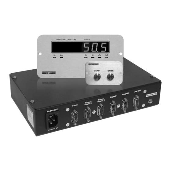
Display and Keypad Figure 1-1 shows the Tracer AV LED display with annunciators and keypad. In setup mode, the keys are used to navigate through menus, select digits within numeric values, and increment/decrement values. See Section 3.1.3 on page 11 for information about using the front panel keys in setup mode. Figure 1-1. -
Page 7: Installation
The shipping carton should contain the enclosure, remote display, remote keypad, this Tracer AV manual, two cables, and a power cord. If any parts were damaged in shipment, notify Rice Lake Weighing Systems and the shipper immediately. Enclosure Security/Disassembly After an NTEP inspector has examined the unit, he/she will install security cables pictured in Figure 2-1 and Figure 2-2. -
Page 8: Cable Connections
Figure 2-2. Tracer AV (back) security cables installed after NTEP certification. Cable Connections Tracer AV provides several cable connections: one for the power cord, one to accommodate the load cell, communications, remote displays, and keypads. Figure 2-3 shows the assignments for the connections. -
Page 9: Illustrations
2.3.1 Illustrations The following illustrations show the Tracer AV CPU board, system configuration, remote display cutout, and remote display drawing. DC INPUT DISPLA Y DRIVERS Micr o- pr ocesso r JMP3 (Factory Only) OF F +3. 3 A / D C O N V E R T E R +5A V LED1 LED2... - Page 10 Figure 2-6. Remote Display Cutout Figure 2-7. Remote Display Drawing Tracer AV Installation Manual...
-
Page 11: Load Cells
Figure 2-8. Switch Panel Cutout Figure 2-9. Switch Panel Drawing 2.3.2 Load Cells The load cell cable is connected to the socketed DB-9 marked load cell. This DB-9 is connected to the CPU board on J1; see the table below for the pin assignments. The DB-9 is for four-wire installations, so leave sense jumper JP1 and JP2 on. -
Page 12: Digital I/O
There are two socketed DB-9 connectors for remote displays which are connected to the serial port J4. The remote display’s DC power and communications are run in the same three-conductor cable. The serial port data is transmitted on the 20 mA pins to the remote displays. DB-9 EDP Port COMM... -
Page 13: Board Removal
Board Removal If you must remove the Tracer AV CPU board, use the following procedure: • Use a wrist strap to ground yourself and protect components from electrostatic discharge (ESD) when working inside the enclosure. Tracer AV • This unit uses line fusing which could create an electric shock hazard. Procedures requiring work inside enclosure must be performed by qualified service personnel only. -
Page 14: Configuration
Configuration To configure the , it must be placed in setup To use , do the following: Tracer AV Revolution mode. Setup mode is initiated by pressing the setup 1. Install the module on a PC Revolution switch on the Tracer AV (see Figure 2-3 4). -
Page 15: Front Panel Configuration
3.1.3 Front Panel Configuration Tracer AV can be configured using a series of menus viewed on the RD-1 display when the Tracer AV is in setup mode. Table 3-1 summarizes the functions of each of the main menus. Menu Menu Function DEFCAL Default Select a 500lb or 300lb default configuration. -
Page 16: Editing Integers
3.1.5 Editing Integers 1. By pressing , navigate all the way to the Units right (beyond all ‘-’ characters until there are no segments flashing). NOTE: The ‘-’ characters are placeholders for appending or removing digits at the end of numbers that exceed the six-digit display. -
Page 17: Configuration Menu
3.2.2 Configuration Menu DEFCAL CONFIG FORMAT CALIBR SERIAL PROGRM SETPNT VERS XXXXXXX XXXXXXX GRADS ZTRKBN ZRANGE MOTBAN OVRLOA SMPRAT FS+2% 15HZ 1000 1.900000 number number number FS+1D 30HZ number FS+9D 60HZ 7.5HZ DIGFL1 DIGFL2 DIGFL3 DFSENS DFTHRH T AREFN 8OUT NONE BOTH 16OUT... - Page 18 CONFIG Menu Description Parameter Choices MOTBAN Sets the level, in display divisions, at which scale motion is detected. If motion is not number detected for 1 second or more, the standstill symbol lights. Some operations, including print, tare, and zero, require the scale to be at standstill. Maximum legal value varies depending on local regulations.
-
Page 19: Format Menu
3.2.3 Format Menu DEFCAL CONFIG XXXXXXX FORMAT CALIBR SERIAL PROGRM XXXXXXX SETPNT VERS PRIMAR SECNDR DSPRAT DECPNT DSPDIV UNITS DECPNT DSPDIV UNITS MULT 250MS 500MS 88888.8 750MS 88888.8 0.453592 88888. 8 1SEC 888888 number 888880 888880 1.5SEC Only used if UNITS =NONE 8.88888 8.88888... - Page 20 FORMAT Menu Parameter Choices Description Level 3 submenus Primary Units (PRIMAR Parameter) DECPNT 88888.8 Decimal point location. Specifies the location of the decimal point or dummy zeroes in the 888888 primary unit display. Value should be consistent with local legal requirements. 888880 8.88888 88.8888...
-
Page 21: Calibration Menu
3.2.4 Calibration Menu See Section 4.0 on page 23 for calibration procedures. DEFCAL CONFIG XXXXXXX FORMAT CALIBR SERIAL PROGRM XXXXXXX SETPNT VERS WZERO WV AL WSPAN REZERO Press Zero key to remove offset from zero and span calibrations Figure 3-7. Calibration Menu CALIBR Menu Parameter Choices... - Page 22 SERIAL Menu Parameter Choices Description Level 2 submenus BAUD Specifies settings for baud rate, data bits, termination characters, end-of-line delay, and echo BITS used by the EDP port. TERMIN EOLDLY ECHO Level 3 Submenus EDP Port and Printer Port BAUD 9600 Baud rate.
-
Page 23: Program Menu
3.2.6 Program Menu DEFCAL CONFIG XXXXXXX FORMAT CALIBR SERIAL PROGRM XXXXXXX SETPNT VERS PWRUPM REGULA CONSNU CONSTU DA TE TIME 000000 000000 NTEP DA TFMT DA TSEP TIMFMT TIMSEP DELAY 24HOUR OIML number number MMDDYY SLASH COLON CANADA 12HOUR DDMMYY DASH COMA NONE... - Page 24 PROGRM Menu Parameter Choices Description Level 3 submenus DATFMT MMDDYY Specifies the format used to display or print the date. DDMMYY YYMMDD DATSEP SLASH Specifies the date separator character. DASH SEMI TIMFMT 24HOUR Specifies the format used to display or print the time. 12HOUR TIMSEP COLAN...
-
Page 25: Setpoint Menu
3.2.7 Setpoint Menu DEFCAL CONFIG FORMAT CALIBR SERIAL PROGRM SETPNT VERS XXXXXXX XXXXXXX XXXXXXX SETPT1 SETPT2 Same as SETPT1 ENABLE KIND V ALUE TRIP BNDVAL HYSTER ACCESS GROSS number HIGHER number number LOWER If TRIP = HIGHER/ INBAND LOWER OUTBAND Figure 3-10. -
Page 26: Version Menu
3.2.8 Version Menu The VERS menu is used to check the software version and reg version installed in the Tracer AV . You can also check the model. VERS DEFCAL CONFIG FORMAT XXXXXXX CALIBR SERIAL PROGRM PFORMT XXXXXXX SETPNT XXXXXXX DIGI N ALGOUT SOFTWR... -
Page 27: Calibration
Calibration ® can be calibrated using the keys, EDP commands, or the configuration Tracer AV Revolution Zero Units utility. Each method consists of the following steps: • Zero calibration • Span calibration • Entering the test weight value • Optional rezero calibration for test weights using hooks or other additional items. -
Page 28: Standard Calibration
6. With displayed, press to show 7. The rezero function is used to remove a WVAL Zero the stored calibration weight. Use the calibration offset when hooks or other items procedure shown in Figure 3-3 12 to enter the are used to hang the test weights. actual value of the test weights to be used for •... -
Page 29: Revolution Calibration
Revolution ® Calibration To calibrate the using , the EDP Tracer AV Revolution More About Calibration p o r t m u s t b e c o n n e c t e d t o a P C r u n n i n g t h e The following topics provide additional information Revolution configuration utility. -
Page 30: Edp Commands
EDP Commands can be controlled by a personal Tracer AV computer or remote keyboard connected to the EDP Command Function port. Control is provided by a set of EDP commands that can simulate front panel key press functions, KZERO In weighing mode, press the Zero key display and change setup parameters, and perform KGROSSNET In weighing mode, press the GROSS/... -
Page 31: Reporting Commands
5.1.2 Reporting Commands 5.1.4 Parameter Setting Commands Reporting commands (see Table 5-2) send specific Parameter setting commands allow you to display or information to the EDP port. These commands can be change the current value for a particular configuration used in both setup mode and normal mode. parameter (Tables 5-3 through 5-11). - Page 32 Command Description Values PRI.DECPNT Primary units decimal position 8.88888, 88.8888, 888.888, 8888.88, 88888.8, 888888, 888880 PRI.DSPDIV Primary units display divisions 1D, 2D, 5D PRI.UNITS Primary units LB, KG, OZ, TN, T, G, NONE SEC.DECPNT Secondary units decimal position 8.88888, 88.8888, 888.888, 8888.88, 88888.8, 888888, 888880 SEC.DSPDIV Secondary units display divisions 1D, 2D, 5D...
- Page 33 Command Description Values CONSNUM Consecutive number 0–999 999 CONSTUP Consecutive number start-up value 0–999 999 DATEFMT Date format MMDDYY, DDMMYY, YYMMDD, YYDDMM DATESEP Date separator SLASH, DASH, SEMI TIMEFMT Time format 12HOUR, 24HOUR TIMESEP Time separator COLON, COMMA Table 5-7. PROGRM EDP Commands Command Description Values...
-
Page 34: Normal Mode Commands
5.1.6 Normal Mode Commands The serial transmit weight data commands (see Table 5-12) transmit data to the EDP port on demand. The SX and EX commands are valid only in normal operating mode; all other commands are valid in either setup or normal mode. -
Page 35: Saving And Transferring Data
Saving and Transferring Data 5.2.2 Downloading Configuration Data from PC to Tracer AV Connecting a personal computer to the Tracer AV Configuration data saved on a PC or floppy disk can port allows you to save configuration data to the PC or be downloaded from the PC to a Tracer AV . -
Page 36: Appendix
A/D reading < –4 mV. Check scale for binding or damage. RNGERR GRADS > 100,000 Only shows up in Config mode. WVAL > 100,000 EEPERR EEPROM Error Call Rice Lake Weighing Systems (RLWS) for service. Table 6-1. Tracer AV Error Messages Tracer AV Installation Manual... -
Page 37: Using The Xe Edp Command
Status Messages 6.1.2 Using the XE EDP Command The XE EDP command can be used to remotely query Two EDP commands, P and ZZ, can be used to for the error conditions shown on the Tracer AV provide status about the Tracer AV . -
Page 38: Continuous Output (Stream) Format
Continuous Output (Stream) Format Figure 6-1 shows the continuous output format sent from the Tracer AV Serial port to the Remote Display. Note: In Setup mode, the text display message follows the following format: <100DM><Time M/S><Text!> or <100DMText!>. <STX> <POL> <wwwwwww> <UNIT> <G/N> <S> <TERM> ASCII 02 G = Gross <CR>... -
Page 39: Front Panel Display Characters
Front Panel Display Characters Figure 6-2 shows the 7-segment LED character set used to display alphanumeric characters on the Tracer AV front panel. < & > Figure 6-2. Tracer AV Display Characters Tracer AV Installation Manual - Appendix... -
Page 40: Conversion Factors For Secondary Units
Conversion Factors for Secondary Units Primary Unit x Multiplier Secondary Unit Tracer AV has the capability to mathematically grains 0.064799 grams convert a weight into many different types of units 0.002286 ounces and instantly display those results with a press of the key. -
Page 41: Digital Filtering
Digital Filtering Tracer AV uses averaged digital filtering to reduce the effect of vibration on weight readings. Adjustable threshold and sensitivity functions allow quick settling by suspending filter averaging, allowing the weight reading to jump to the new value. Figure 6-3 shows the digital filter parameters on the CONFIG menu. DIGFL1 DIGFL2 DIGFL3... -
Page 42: Setting The Digital Filter Parameters
6.6.3 Setting the Digital Filter Parameters Fine-tuning the digital filter parameters greatly improves Tracer AV performance in heavy-vibration environments. Use the following procedure to determine vibration effects on the scale and optimize the digital filtering configuration. 1. In setup mode, set all three digital filters (DIGFL1, DIGFL2, DIGFL3) to 1. Set DFTHRH to NONE. Return the Tracer AV to normal mode. -
Page 43: Test Mode
Test Mode In addition to normal and setup modes, test mode To enter test mode, press and hold the setup switch provides a number of diagnostic functions for the until the front panel display shows the word TEST , including: After about three seconds, the test mode display Tracer AV automatically shifts to the first test menu function,... -
Page 44: Regulatory Mode Functions
Regulatory Mode Functions Front Panel Key Function REGULAT Parameter Value Weight on Scale Tare in System TARE ZERO NTEP zero or negative no action ZERO CLEAR TARE positive TARE TARE CANADA zero or negative no action TARE CLEAR TARE positive TARE no action OIML... -
Page 45: 6.10 Specifications
6.10 Specifications Serial Communications EDP Port Full duplex RS-232 Power Printer Port Full duplex RS-232 or active transmit Line Voltages 115 or 230 VAC only 20 mA current loop Frequency 50 or 60 Hz Both Ports 38400, 19200, 9600, 4800, 2400, Power Consumption 1.5 A @ 115 VAC (8W) 1200, 600, 300 bps;... -
Page 46: Tracer Av Limited Warranty
Tracer AV Limited Warranty Rice Lake Weighing Systems (RLWS) warrants that all RLWS equipment and systems properly installed by a Distributor or Original Equipment Manufacturer (OEM) will operate per written specifications as confirmed by the Distributor/OEM and accepted by RLWS. All systems and components are warranted against defects in materials and workmanship for two years. - Page 48 PN 98316 02/11...
Need help?
Do you have a question about the REVOLUTION Tracer AV and is the answer not in the manual?
Questions and answers