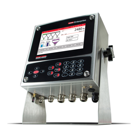
Rice Lake 1280 Enterprise Series Technical Manual
Color touchscreen indicator
Hide thumbs
Also See for 1280 Enterprise Series:
- Technical manual (176 pages) ,
- Installation manuals (46 pages) ,
- Operation manuals (24 pages)

Related Manuals for Rice Lake 1280 Enterprise Series


Summary of Contents for Rice Lake 1280 Enterprise Series
- Page 1 1280 Enterprise Series ™ Color Touchscreen Indicator Technical Manual August 21, 2019 PN 167659 Rev I...
- Page 2 All information contained within this publication is, to the best of our knowledge, complete and accurate at the time of publication. Rice Lake Weighing Systems reserves the right to make changes to the technology, features, specifications and design of the equipment without notice.
-
Page 3: Table Of Contents
Water/Dust Tight Cord Grips ..............27 Technical training seminars are available through Rice Lake Weighing Systems. - Page 4 TCP Command Server............... . 72 Rice Lake continually offers web-based video training on a growing selection of product-related topics at no cost.
- Page 5 11.1 Updating the Scale Card Firmware ..............108 Technical training seminars are available through Rice Lake Weighing Systems.
- Page 6 Softkey Widgets ................143 Rice Lake continually offers web-based video training on a growing selection of product-related topics at no cost.
- Page 7 17.0 Specifications ............... . 163 Technical training seminars are available through Rice Lake Weighing Systems.
- Page 8 1280 Series Color Touchscreen Indicator Rice Lake continually offers web-based video training on a growing selection of product-related topics at no cost. Visit www.ricelake.com/webinars www.RiceLake.com Visit our website...
-
Page 9: Introduction
Do not operate or work on this equipment unless this manual has been read and all instructions are understood. Failure to follow the instructions or heed the warnings could result in injury or death. Contact any Rice Lake Weighing Systems dealer for replacement manuals. -
Page 10: Features
1280 Series Color Touchscreen Indicator Features Features of the 1280 include: • Support for up to eight scales (combination of analog load cell, total, serial scales or program scales) • Eight programmable Digital I/O bits available on the CPU board (connector J1) including onboard pulse input pins, with 24 additional per option card •... -
Page 11: Weigh Mode
When a system reset is performed (Version 1.05 and later) the Weigh Mode display is populated with a scale widget Note and a softkey widget. This gives end users access to softkey setup without having to use EDP commands or revolution. © Rice Lake Weighing Systems ● All Rights Reserved... -
Page 12: Numeric/Alpha Entry
1280 Series Color Touchscreen Indicator Numeric/Alpha Entry When data entry is required, a keyboard or a numeric keypad displays on the screen. The indicator’s front panel is also equipped with a numeric keypad. Figure 1-2. On-screen Alphanumeric Keyboard Figure 1-3. On-screen Numeric Keypad Item No. -
Page 13: Main Menu User Interface
14. If hooks or chains were used during calibration, remove these and the test weights from the scale. The re-zero function is used to remove a calibration offset when hooks or chains are used to hang the test weights during both zero and span calibration. 15. Press Re-Zero © Rice Lake Weighing Systems ● All Rights Reserved... -
Page 14: Setpoints
1280 Series Color Touchscreen Indicator 1.5.2 Setpoints Targets are a set of values which when met, cause the setpoint to trip. Parameter Default Description Value Setpoint Value: Weight-based – specifies the target weight value, 0–9999999 Time-based – specifies time in 0.1 second intervals, range 0–65535 Counter –... -
Page 15: Language
1280. Figure 1-7. Virtual Keypad Functions Keyed Tare is the equivalent to the keyed tare softkey. Press , a numeric keypad displays to enter a tare value. © Rice Lake Weighing Systems ● All Rights Reserved... -
Page 16: Toggle Gross/Net Mode
1280 Series Color Touchscreen Indicator 1.6.1 Toggle Gross/Net Mode Press to toggle the display mode between gross and net. • If a tared value is in the system, Net is displayed (net equals gross minus tare) • If there is no tare in the system, Gross is displayed 1.6.2 Toggle Units Press... -
Page 17: Accumulator Functions
1. To enter navigation softkey designations for the 7'' panel mount, navigate to the main menu and select Configuration/ Features/Softkeys. 2. Press 3. Scroll to the desired softkey and press Done. Figure 1-8. Softkeys © Rice Lake Weighing Systems ● All Rights Reserved... -
Page 18: Keypad Operations
1280 Series Color Touchscreen Indicator Keypad Operations Display/Virtual keypad Navigation Keys Numeric Keypad Figure 1-9. 1280 Front Panel 1.7.1 Navigation Keys Navigation keys are primarily linked to iRite handlers. If no iRite handlers exist, the navigation keys toggle through a selection of displayed scales. -
Page 19: Tare
• A Display or Clear Accumulator Digital Input can be activated • A serial command can be sent Print the Accumulated Value To print the accumulated value, press while displaying the accumulator. © Rice Lake Weighing Systems ● All Rights Reserved... -
Page 20: Alibi Storage
1280 Series Color Touchscreen Indicator Alibi Storage Alibi storage is a database of past transactions listed by date. This allows previous print transactions to be recalled and reprinted. Alibi storage is enabled using the Features menu in configuration mode. Print transactions can be recalled by assigning a softkey to Alibi. -
Page 21: Setpoint Entry
Screen Display a different screen by entering a value (1–99) and pressing the Screen softkey Database Accesses the import and export database feature from the weigh mode Table 1-6. Configurable Softkeys © Rice Lake Weighing Systems ● All Rights Reserved... -
Page 22: Installation
Immediately after unpacking, visually inspect the 1280 to ensure all components are included and undamaged. The shipping carton should contain the controller, display, CD, parts kit, any options ordered with the unit and the appropriate manuals. If any parts were damaged in shipment, notify Rice Lake Weighing Systems and the shipper immediately. Mounting/Assembly There are three enclosure styles –... -
Page 23: Universal Mount Enclosure With Tilt Stand
2. Pull the door and fully extend the hinge to swing the door open. 3. The bracket is loose, remove it from the enclosure. Retain shipping bracket for future shipping needs. Note © Rice Lake Weighing Systems ● All Rights Reserved... - Page 24 1280 Series Color Touchscreen Indicator Controller Disassembly The controller can be tilted up with the locking tab or it can be completely removed from the enclosure by removing Note the retaining wire bail. 1. Remove the large fillister screw in the back of the indicator to tilt or remove the controller. The seal must be broken for this purpose.
- Page 25 This illustration is not to scale and is for illustration purposes only. Use the dimensions to mark the holes for the IMPORTANT universal mount, or use the bottom of the tilt stand as a template. Do not use this figure as a template. © Rice Lake Weighing Systems ● All Rights Reserved...
- Page 26 1280 Series Color Touchscreen Indicator Sealing the Setup Switch In certain Legal for Trade applications, it may be necessary to seal the indicator to restrict access from the setup switch. Use the following instructions to seal the universal enclosure. The audit trail jumper (JP1) needs to be disabled, in the off (right) position, in order to seal the setup switch with IMPORTANT a lead seal wire.
-
Page 27: Wall Mount Enclosure
1. Loosen the four screws on the front door. 2. Swing the door open. 3. Remove the four screws securing the bracket in place. 4. Remove bracket from the enclosure. Screws Shipping Bracket Figure 2-9. Remove Shipping Bracket © Rice Lake Weighing Systems ● All Rights Reserved... - Page 28 1280 Series Color Touchscreen Indicator Controller Disassembly Figure 2-10. Open Door 1. Loosen the four screws on the front door. 2. Swing the door open. 3. Remove the wires connected to the controller assembly. Slide Mounting Controller Plate Down Assembly Figure 2-11.
- Page 29 Alternatively, the A/D scale card includes fillister screws and a bracket that prevent the load cell cable from being disconnected. Hole in Door Enclosure Large Screw Figure 2-13. Seal the Front Door © Rice Lake Weighing Systems ● All Rights Reserved...
-
Page 30: Panel Mount Installation
1280 Series Color Touchscreen Indicator 2.2.4 Panel Mount Installation The panel mount ships partially assembled. The display assembly must be removed from the DIN rail bracket for installation. 1. Remove the two screws securing the DIN rail bracket to the display assembly. 2. - Page 31 4.11" 4.66" 6.22" Ø 1.00" 1.00" Figure 2-16. 7'' Touch-Only Panel Mount Dimensions 14.00" 0.78" 12.44" Ø 0.22" 5.62" 10.00" 8.44" Ø 1.00" 1.00" Figure 2-17. 12'' Touch-Only Panel Mount Dimensions © Rice Lake Weighing Systems ● All Rights Reserved...
- Page 32 1280 Series Color Touchscreen Indicator Install Grounding Bus Bar The grounding bus bar is installed on the controller assembly for grounding purposes on the panel mount. 1. Remove the four corner screws from the controller assembly. 2. Align the bus bar to the screw holes and secure by reinstalling the screws. Figure 2-18.
- Page 33 Assembly does not need to be removed from the enclosure to seal the setup switch and the grounding bus bar can remain attached, if installed. Large Fillister Screw DIN Rail Clip Figure 2-22. Seal the Setup Switch (Panel Mount Enclosure) © Rice Lake Weighing Systems ● All Rights Reserved...
- Page 34 1280 Series Color Touchscreen Indicator Use the following instructions to install option cards. There are two SPI communication buses for the six option card slots: one for slots 1, 2 and 3 and one for slots 4, 5 and 6. Communication is faster with less traffic on an SPI bus. For optimal performance, populate slots 1 and 4 first in order to keep cards on their own SPI bus.
-
Page 35: Cable Connections
Gland (PN) Diameter PG13.5 (169876) 0.264-0.472'' (6.7-12 mm) PG13.5 (15665) 0.157-0.354'' (4-9 mm) PG9 (169875) 0.157-0.314'' (4-8 mm) PG9 (15664) 0.118-0.236'' (3-6 mm) Table 2-2. Cord Grip and Reducing Gland Diameters © Rice Lake Weighing Systems ● All Rights Reserved... -
Page 36: Shield Grounding Through Cord Grips
1280 Series Color Touchscreen Indicator 2.3.2 Shield Grounding Through Cord Grips To ground cables to the universal or wall enclosures, route the cable through one of the metal cord grips. Ensure the exposed shielding makes contact with the tabs of the grounding washer inside the cord grip. Grounding Washer Figure 2-27. -
Page 37: Esd Grounding For Touch Only Models
Keps nut. PN 193810 ground clamp has a smaller radius and must be used with the touchscreen cable. Figure 2-30 on page 30 is for illustration only and may not represent all panel mount applications. Grounding location Note and exact stud placement may vary. © Rice Lake Weighing Systems ● All Rights Reserved... - Page 38 1280 Series Color Touchscreen Indicator Display Cable Small Ground Clamp Ground Clamp Touchscreen Cable Grounding Strap Figure 2-30. Panel Mount Shield Grounding Figure 2-29 on page 29 Ensure the small ground clamp is installed first then install the ground clamp, see Note 6.
-
Page 39: Load Cells
The A/D scale card must be removed from the controller prior to configuring the sense line jumpers. IMPORTANT The hardware of J2 is not populated on a single A/D scale card. Note © Rice Lake Weighing Systems ● All Rights Reserved... -
Page 40: Serial Communications
1280 Series Color Touchscreen Indicator 2.3.6 Serial Communications The two communication ports on the 1280 CPU board support full duplex RS-232, RS-422 or RS-485 communications at up to 115200 bps. POWER LVDS DISPLAY KEYBOARD Light pipes and mounting plate removed for clarity BAT1 PCIe PCIe... -
Page 41: Cpu Digital I/O Wiring
6. Plug the connector into J1 on the board. Connector Signal +5 VDC DIO 1 DIO 2 DIO 3 DIO 4 DIO 5 DIO 6 DIO 7 DIO 8 Table 2-6. CPU Digital I/O Pin Assignments © Rice Lake Weighing Systems ● All Rights Reserved... -
Page 42: Wiring Schematics
2-33. To Touch Screen To Overlay Keypad Figure 2-34 on page 35 7'' and 12'' display wiring Display HMI Board To Wall Outlet To Fan ASSY RICE LAKE PN/Rev R266 R265 Power Supply Back Plane KEYBOARD LVDS DISPLAY POWER BAT1... -
Page 43: Touch Screen Only (Virtual Keypad)
Connect CPU to display cable (PN 164995 or 164970) from J9 to 7'' display. Connect CPU to display cable (PN 180001) from J9 and J18 on the bottom of CPU board to 12'' display. Additional cable lengths are available. Note © Rice Lake Weighing Systems ● All Rights Reserved... -
Page 44: Configuration Methods
1280 Series Color Touchscreen Indicator Configuration Methods The indicator can be configured using: • Front panel keys to navigate through a series of configuration menus; see Section 3.0 on page 50 ® • Revolution configuration utility; see Section 13.0 on page 113 •... -
Page 45: Cpu Board Replacement
2. Remove the two screws securing the CPU board to the face plate. Antenna Nut Screw and Washer Figure 2-36. CPU Board and Face Plate 3. Separate the face plate and the CPU board. Reverse procedure for reassembly. © Rice Lake Weighing Systems ● All Rights Reserved... -
Page 46: Power Supply Replacement
1280 Series Color Touchscreen Indicator Power Supply Replacement Always disconnect power before opening the indicator. WARNING Use a wrist strap to ground yourself and protect components from electrostatic discharge (ESD) when working IMPORTANT inside the indicator enclosure. *Procedures requiring work inside the indicator must be performed by qualified service personnel only. *In the wall and universal mounts, the supply cord serves as the power disconnect. -
Page 47: Replace Fan Plate And Back Plane
Orientation of the fan prior to removal. It is important the fan is reinstalled in the correct orientation. Note Figure 2-39. Remove Fan 3. Loosen the four screws securing the fan to the fan plate and remove the fan. Reverse this procedure for reassembly. © Rice Lake Weighing Systems ● All Rights Reserved... -
Page 48: Replacement Parts
1280 Series Color Touchscreen Indicator Replacement Parts Inside Bottom of Enclosure (some items are hidden for clairity) Figure 2-40. Universal Repair Parts www.RiceLake.com Visit our website... - Page 49 183663 Tall Flanged Drilled Hex Head Screw 169676 Controller Assembly (Figure 2-42 on page 169452 Enclosure Shell Assembly, Universal 169875 Cord Grip, PG 9 With Nut Table 2-7. Universal Parts List © Rice Lake Weighing Systems ● All Rights Reserved...
- Page 50 1280 Series Color Touchscreen Indicator Cover exploded for clarity Inside Bottom of Enclosure (some items hidden for clarity) Figure 2-41. Wall Mount Repair Parts www.RiceLake.com Visit our website...
- Page 51 Cord, US Power 124695 Panel Plug, Round Solid 165112 Cord, European Power 169876 Cord Grip, PG13.5 With Nut 169875 Cord Grip, PG 9 With Nut Table 2-8. Wall Mount Repair Parts List © Rice Lake Weighing Systems ● All Rights Reserved...
- Page 52 1280 Series Color Touchscreen Indicator Figure 2-42. Controller Assembly Repair Parts Item No. Part No. Description 169350 Fan Mount Plate Assembly • CPU, Rev A, Requires Rev A Fan Plate • CPU, Rev B, Requires Rev A Fan Plate • CPU, Rev C, Requires Rev B Fan Plate •...
- Page 53 Installation Figure 2-43. 7''-Inch Panel Mount Repair Parts © Rice Lake Weighing Systems ● All Rights Reserved...
- Page 54 1280 Series Color Touchscreen Indicator Item No. Part No. Description Item No. Part No. Description 166838 Bracket Assembly, DIN Rail 169930 Enclosure Face Plate Assembly (Inc 1-7) 163786 Parts Kit, Panel (Inc. 16-25 and all NS) 169929 Face Panel 1280 168872 Wire, 9'' Ground, 1/4'' Eye 160379...
- Page 55 Screw, Mach 6-32NC x 3/8 Thread Rolling Phillips Pan Head Zinc Plated 169676 1280 Controller Assembly, See Figure 2-11 on page 20 Table 2-12. 7'' Touch-Only Panel Mount Repair Parts List © Rice Lake Weighing Systems ● All Rights Reserved...
- Page 56 1280 Series Color Touchscreen Indicator Figure 2-45. 12'' Touch-Only Panel Mount Repair Parts Item No. Part No. Description 176126 Touchscreen Overlay, 12-Inch 1280 Panel Mount Display 176127 Front Panel Assembly, 12-Inch 1280 Panel Mount 176404 Gasket, 1280 12-Inch Display Panel Mount 177396 Display Module, 12.1-Inch WXGA/HB 1500 NIT Industrial LED 176242...
-
Page 57: Label Legend
Label, Serial Option 167195 Label, Relay Option 167196 Label, Analog Output (Single) Option 167197 Label, Analog Output (Dual) Option 167198 Label, Analog Input/Thermocouple (Dual) Option Table 2-14. Label Repair Parts List © Rice Lake Weighing Systems ● All Rights Reserved... -
Page 58: Configuration Menu
1280 Series Color Touchscreen Indicator Configuration Menu Configuration has a series of menus which allow the parameters of the indicator to be set up. Detailed descriptions of the Scale Configuration, Communications, Features, Formats, Digital I/O, Analog Output, Setpoints and Diagnostics menus are provided Section 4.0 on page 54 through Section 11.0 on page... - Page 59 Figure 3-3. Jumper Locations The front door to the indicator may also be sealed to prevent access to the hardware. This may be required in some Note Legal for Trade applications. © Rice Lake Weighing Systems ● All Rights Reserved...
-
Page 60: Configuration Menu
1280 Series Color Touchscreen Indicator Configuration Menu VX.XX.XX Figure 3-4. Configuration Menu Item No. Selection Description Scales Menu Set the scale parameter, see Section 4.0 on page 54 Communications Menu Set the communication parameters, see Section 5.0 on page 66 Features Menu Set features parameters, see Section 6.0 on page 74... -
Page 61: Configuration Menu Map
Slot X Section 8.0 Analog Out Analog Output X Section 9.0 Setpoints Setpoint 1-100 General Targets Preacts Actions Digital I/O Settings Section 10.0 Diagnostics Devices Section 11.0 Figure 3-5. Configuration Menu Map © Rice Lake Weighing Systems ● All Rights Reserved... -
Page 62: Scale Configuration
1280 Series Color Touchscreen Indicator Scale Configuration The Scales menu allows the setup of parameters for the type of scale to be set up. From the Configuration menu, press to enter the Scales menu. Once all parameters have been set, press to return to weigh mode. -
Page 63: Scale Alias
Figure 4-3. Scales Alias Setup Screen 1. Press . The keyboard displays on the screen. 2. Use the keyboard to enter the desired alias (up to 16 characters). 3. Press when scale alias is correct. Done © Rice Lake Weighing Systems ● All Rights Reserved... -
Page 64: Scale Format
1280 Series Color Touchscreen Indicator 4.1.2 Scale Format The Scale Format menu varies depending on which scale kind is being used. Only settings available for the selected scale kind display. Options specific to the scale feature chosen are in blue font on the screen. Parameter Default Description... -
Page 65: Split Mode
5. Set the Mid Range Capacity (MRMI) if desired (optional). When set, the Mid Range Decimal Position and Mid Range Display Division parameters display in blue text under Mid Range Capacity (MRMI). © Rice Lake Weighing Systems ● All Rights Reserved... -
Page 66: Scale Calibration
1280 Series Color Touchscreen Indicator 6. Calibrate scale, see Section 4.2. Range 1: Up to 100 lb will count by 1 lb Range 2: 100 to 500 lb will count by 5 lb Range 3: 500 lb to capacity will count by 10 lb Figure 4-4. - Page 67 13. The re-zero function is used to remove a calibration offset when hooks or chains are used to hang the test weights during both zero and span calibration. If hooks or chains were used during calibration, remove these and the test weights from the scale. 14. Press Re-Zero © Rice Lake Weighing Systems ● All Rights Reserved...
-
Page 68: Multi-Point Calibration
1280 Series Color Touchscreen Indicator 4.2.2 Multi-Point Calibration A multi-point calibration is performed by entering up to four additional calibration points. Figure 4-6. Multi-Point Calibration Item No. Description 123... – press to enter the test weight value Press to Calibrate – captures the calibration value for each point; only available after a test weight value has been entered; displays Calibration Complete after the calibration is finished Table 4-7. -
Page 69: Theoretical Calibration
Used for flow control to get a smooth increase in weight; it takes two-thirds of the difference in weight (seconds) change in each time period specified Table 4-8. Filtering Menu Descriptions © Rice Lake Weighing Systems ● All Rights Reserved... -
Page 70: Adaptive Digital Filter
1280 Series Color Touchscreen Indicator 4.3.1 Adaptive Digital Filter The adaptive digital filter has two parameters, the response time and observe noise (instability): Filter Sensitivity and Filter Threshold (Display Divisions). These parameters display in blue text after the Digital Filter Type is set to Adaptive Digital Filter. -
Page 71: Scales Setup
Specifies the time (in seconds) which the scale must be out of motion before it is considered to be at standstill* (Seconds) Accumulator Accumulation can be toggled On/Off. If on, accumulation occurs on print operation; if off, an accumulation does not occur Table 4-11. Scales General Descriptions © Rice Lake Weighing Systems ● All Rights Reserved... -
Page 72: Maintenance
1280 Series Color Touchscreen Indicator Parameter Default Description Peak Hold Used to determine, display and print the greatest weight read during a weighing cycle; the weighing cycle ends when a print command is executed (AUTO setting) or when the peak weight is cleared by pressing Zero or Print;... -
Page 73: Industrial Scales
No matter the type, if the data received does not match exactly (as defined by the stream format configuration), the data is thrown out and a scale error occurs. © Rice Lake Weighing Systems ● All Rights Reserved... -
Page 74: Communications
1280 Series Color Touchscreen Indicator Communications The Communications menu is used for the setup of communication parameters for the 1280. From the Configuration menu, select to enter the Communications menu. Once all parameters have been set, press to return to weigh mode. Scroll for additional parameters Figure 5-1. -
Page 75: Serial Menu
Allows the serial port to be renamed Echo Specifies whether characters received by the port are echoed back to the sending unit Response Specifies whether the port transmits replies to serial commands Table 5-3. Serial Port Parameters © Rice Lake Weighing Systems ● All Rights Reserved... -
Page 76: Ethernet Menu
1280 Series Color Touchscreen Indicator Parameter Default Description Outgoing Line CR/LF Selects termination character for data sent from the port Termination End of Line Delay Sets delay period from when a formatted line is terminated to the beginning of the next formatted serial output; range (seconds) acceptable is 0.0–25.5 seconds iQube2 Sample... -
Page 77: Using An Internet Browser As A Remote Display
IP address for the server Secondary DNS Server 0.0.0.0 IP address for the server Gateway Address 0.0.0.0 Default gateway MAC Address View the MAC Address, in hexadecimal base (read only) Table 5-5. Wired Adapter Parameters © Rice Lake Weighing Systems ● All Rights Reserved... -
Page 78: Wi-Fi Adapter
1280 Series Color Touchscreen Indicator 5.2.4 Wi-Fi Adapter When Wi-Fi Adapter is selected, the parameters in Table 5-6 display. Parameter Default Description Enable Wi-Fi Ethernet Communications – Off speeds up the booting process and configuration Enable mode to weigh mode transitions Service Set ID (SSID) Name of the wireless local area network (WLAN) Network Type... - Page 79 Using Wi-Fi Direct does not interrupt the use of Wi-Fi. Note Enabling the Wi-Fi requires Wi-Fi Direct to be re-initiated. Wi-Fi direct can utilize all Ethernet connection types (TCP command server, Stream Server, TCP Client 1 & 2). © Rice Lake Weighing Systems ● All Rights Reserved...
-
Page 80: Tcp Command Server
1280 Series Color Touchscreen Indicator 5.2.6 TCP Command Server Parameter Default Description Input Type Command Processor Sets the input type Server Port Number 10001 TCP/IP port number Alias Allows the server to be renamed Echo Specifies whether characters received by the port are echoed back to the sending unit Response Specifies whether the port transmits replies to serial commands Outgoing Line Termination... -
Page 81: Iqube2 Scale
5. Press iQube2 setup to enter the iQube2 setup mode. 6. A popup asking Enter iQube2 setup mode displays. 7. Press to enter the iQube2 setup mode. 8. Refer to the iQube2 manual (PN 67888) for setup information. © Rice Lake Weighing Systems ● All Rights Reserved... -
Page 82: Features
1280 Series Color Touchscreen Indicator Features The Features menu allows the setup of parameters for the menu items listed in Table 6-1. From the Configuration menu, select (circled in Figure 6-1) to enter the Features menu. Once all parameters have been set, select to return to weigh mode. -
Page 83: Softkeys
Contrast Adjusts the screen backlight intensity Test Not available in version 1.00 Stop Sends AuxFmt13 out its configured port to display a red light on a LaserLight Table 6-2. Configurable Softkeys © Rice Lake Weighing Systems ● All Rights Reserved... -
Page 84: Database Softkey
1280 Series Color Touchscreen Indicator Softkey Description Sends AuxFmt12 out its configured port to display a green light on a LaserLight Sends AuxFmt14 out its configured port to turn a LaserLight red/green light off Display Unit ID Displays the Unit ID in the lower left corner of the screen Zero Zeros the indicator Gross/Net... -
Page 85: Laserlight Softkey
127.0.0.1; if a local/remote application, set this parameter, on the remote indicator only, to the IP address of the local indicator to use its display Table 6-4. General Parameters Menu © Rice Lake Weighing Systems ● All Rights Reserved... -
Page 86: Local/Remote Operation
1280 Series Color Touchscreen Indicator 6.2.1 Local/Remote Operation Local/remote support provides a function equivalent to the indicator via web server with network access. The display on the local indicator is also displayed at the remote unit, and keypad input from the remote unit is treated the same as keypad input on the local indicator. -
Page 87: Parameters Available In All Regulatory Modes
Tare No action Industrial Mode Table 6-8 on page 80 NONE Zero or negative Tare Zero Clear Tare Positive Tare Clear Tare Table 6-7. Tare/Zero Key Functions for Regulatory Parameter Settings © Rice Lake Weighing Systems ● All Rights Reserved... - Page 88 1280 Series Color Touchscreen Indicator Industrial Mode Parameters Industrial mode provides a set of sub-parameters to allow customization of tare, clear and print functions in non-Legal for Trade scale installations. Parameter Default Description Audit Agency NTEP Defines how the Audit Trail data is displayed/printed, depending on the requirements for the various regulatory agencies Weight Source for Print Synchronized...
-
Page 89: Passwords
• English • Spanish • French • Portuguese • Italian • German • Dutch • Danish • Swedish • Russian • Ukrainian • Hebrew • Arabic • Thai • Chinese • Turkish © Rice Lake Weighing Systems ● All Rights Reserved... -
Page 90: Contact Info
1280 Series Color Touchscreen Indicator Contact Info Enter the Contact Info menu to setup company information. 1. Press , select Contact Info. 2. Press the parameter to be set. A keyboard displays. 3. Enter the information and press Done 4. Repeat Step 1 Step 2 until all desired entries have been made. -
Page 91: Initialize Ftp Server
The 1280 supports Direct Print and Internet Printing Protocol for printing directly to a printer. URI examples include: Note socket://<ip-address-of printer>:9100 ipp://<ip-address-of-printer>:631. 6. Press to complete the setup. Printer successful installed displays. Next > © Rice Lake Weighing Systems ● All Rights Reserved... -
Page 92: View Alibi Storage
1280 Series Color Touchscreen Indicator View Alibi Storage Allows previous print transactions to be recalled and reprinted. Approximately 500,000 alibi messages can be stored. Set the Alibi Storage to On by entering the regulatory menu under features, see Section 6.3.1 on page 1. -
Page 93: Formats
Table 7-2 on page 86, or the data frame can be customized Selection Field Allows selection of print or stream formats Table 7-1. Format Menu Parameters © Rice Lake Weighing Systems ● All Rights Reserved... -
Page 94: Print Format
1280 Series Color Touchscreen Indicator Print Format The print format used for a given print operation depends on the indicator configuration and the operation performed. Each print format can be customized to include up to 1000 characters of information, such as company name and address, on printed tickets. -
Page 95: Set Destination 1 And 2 Print Format
Time of last accumulation, current scale <AT#n> Time of last accumulation, scale n <AD> Date of last accumulation, current scale <AD#n> Date of last accumulation, scale n Table 7-4. Print Format Tokens © Rice Lake Weighing Systems ● All Rights Reserved... - Page 96 1280 Series Color Touchscreen Indicator Token Description Supported Ticket Formats Setpoint Tokens <SCV> Setpoint captured value SPFMT <SN> Setpoint number <SNA> Setpoint name <SPM> Setpoint mode (gross or net label) <SPV> Setpoint preact value <STV> Setpoint target value Auditing Tokens <CD>...
-
Page 97: Stream Format Menu
Table 7-6 on page 90. Press Done 8. Press Stream Destinations to indicate where to stream. 9. Press Done 10. Set the values for the Stream Tokens as needed, see Table 7-5. © Rice Lake Weighing Systems ● All Rights Reserved... -
Page 98: Stream Format Tokens
1280 Series Color Touchscreen Indicator 7.2.1 Stream Format Tokens Format Identifier Defined By Description <P[G | N | T]> STRM.POS#n Polarity – specifies positive or negative polarity for the current or specified (Gross/Net/ STRM.NEG#n Tare) weight on the source scale. Possible values are SPACE, NONE, + (for STR.POS#n) or –... - Page 99 <CR> Carriage return <LF> Line feed Table 7-6. Stream Format Tokens (Continued) © Rice Lake Weighing Systems ● All Rights Reserved...
-
Page 100: Digital I/O
1280 Series Color Touchscreen Indicator Digital I/O Digital inputs can be set to provide indicator functions, including all keypad functions. Digital inputs are active low (0 VDC) and inactive high (5 VDC). Digital outputs are typically used to control relays drive other equipment. Outputs are designed to sink, rather than source, switching current. - Page 101 Allows ability to count pulses using a custom iRite application; the maximum pulse input frequency is 5 kHz Example: to measure water being metered into a tank. Table 8-1. Digital I/O Types © Rice Lake Weighing Systems ● All Rights Reserved...
-
Page 102: Analog Output
1280 Series Color Touchscreen Indicator Analog Output The Analog Output menu is only functional if the analog output option card is installed. If it is not installed, the menu is visible, but not functional. If the analog output option is installed, configure all other indicator functions and calibrate the indicator before configuring the analog output. -
Page 103: Analog Output Calibration
Step 6 through Step 15 until calibration results are satisfactory. 17. Press Finish. The display returns to the Analog Output menu. 18. Press Save and Exit to save the calibration parameters. © Rice Lake Weighing Systems ● All Rights Reserved... -
Page 104: Setpoints
1280 Series Color Touchscreen Indicator 10.0 Setpoints The 1280 indicator provides 100 configurable setpoints for control of the indicator and external equipment functions. Setpoints can be configured to perform actions or functions based on specified parameter conditions. Parameters associated with various setpoint kinds can be configured to: •... -
Page 105: Select Setpoint For Configuration
Table 10-2. Setpoint Kinds © Rice Lake Weighing Systems ● All Rights Reserved... - Page 106 1280 Series Color Touchscreen Indicator Parameter Description Batch Continuous Pause Pauses the batch sequence indefinitely; a Batch Start signal must be initiated to continue the batch process Delay Delays the batch sequence for a specified time; the length of the delay (in tenths of a second) is specified on the Value parameter Wait Standstill Suspends the batch sequence until the scale is at standstill...
-
Page 107: Setpoint Configuration
Wait Standstill Quiet Digital I/O Sense Slot None Normal Slot 1-6 Invert Settings Batch Access Enable Alias Prompt Enter Enter Value Value Hide Branch Figure 10-3. Gross/Net/Negative Gross/Negative Net Setpoint Parameters © Rice Lake Weighing Systems ● All Rights Reserved... - Page 108 1280 Series Color Touchscreen Indicator Accumulate Target Value Source Trip Enter Scale Higher/Lower Inband/Outband Value Band Value Preact No parameters to be set. Actions Push Tare Alarm Clear Accum. Clear Tare Push Accum. Push Print Quiet Wait Standstill Digital I/O Sense Slot None...
- Page 109 Slot 1-6 Invert Settings Branch Access Alias Prompt Settings Enter Enter Enter Access Alias Prompt Value Value Value Enter Enter Hide Value Value Hide Figure 10-7. Wait Standstill and Counter Setpoint Parameters © Rice Lake Weighing Systems ● All Rights Reserved...
- Page 110 1280 Series Color Touchscreen Indicator Center Of Zero/In-Motion/In-Range Auto-Jog Target Target Source Source Scale Scale 1-8 Preact Preact No parameters to be set. No parameters to be set. Actions Actions No parameters to be set. Push Accum. Push Print Push Tare Clear Accum.
- Page 111 None Normal Slot 1-6 No parameters to be set (Always only). Invert Settings Access Prompt Batch Alias Enter Enter Value Value Hide Figure 10-11. Time of Day and Always/Never Setpoint Parameters © Rice Lake Weighing Systems ● All Rights Reserved...
-
Page 112: Targets
1280 Series Color Touchscreen Indicator Digital Input Count Target Digital Input Slot Mask Value Pre-Count Enter Enter Enter Enter Slot Value Value Value Preact No parameters to be set. Actions No parameters to be set. Digital I/O Sense Slot None Normal Slot 1-6 Invert... -
Page 113: Preacts
Turns the setpoint On (default) or Off Enable Alias Enter a name for the setpoint Prompt Alphanumeric message or prompt which can be displayed in a label widget Table 10-7. Settings Parameters © Rice Lake Weighing Systems ● All Rights Reserved... -
Page 114: Batch Operations
1280 Series Color Touchscreen Indicator 10.3 Batch Operations Softkeys can be configured to allow operator control of batch operations from the 1280 front panel, or they can be configured using <Prodfont>Revolution III, serial commands or the Features menu, see Section 6.1 on page Display or change assigned setpoints. - Page 115 3. Unlock STOP button (OUT position). A new batch can now be started. Use this procedure (or the BATRESET serial command) to initialize the new batch routine following any change to the Note setpoint configuration. © Rice Lake Weighing Systems ● All Rights Reserved...
-
Page 116: Diagnostics
1280 Series Color Touchscreen Indicator 11.0 Diagnostics From the Configuration menu, select the Diagnostics icon (circled in Figure 11-1) to enter the Diagnostics menu. Once all settings are correct, select to return to weigh mode. Figure 11-1. Diagnostics Menu 11.1 Updating the Scale Card Firmware Follow the steps below to update scale card firmware: If this process is not followed as described below, including power cycling, the scale card could be damaged IMPORTANT... -
Page 117: Devices
2. Press Yes to calibrate the touchscreen on the next indicator restart. Figure 11-2. Reset Touchscreen Calibration Prompt 3. Press Yes to restart the indicator. The indicator test runs. At 50% complete, the calibration utility displays. Figure 11-3. Restart Indicator Prompt © Rice Lake Weighing Systems ● All Rights Reserved... - Page 118 1280 Series Color Touchscreen Indicator TSLIB calibration utility Touch crosshair to calibrate Figure 11-4. Calibration Utility Display 4. Touch each cross hair (five total) with a stylus or similar object when prompted. When the center cross hair has been touched, allow the indicator test to continue until the main menu displays. Be very precise while calibrating the touchscreen.
-
Page 119: Option Cards
61 = Serial Communications card 99 = Single Channel Analog Output card 90 = Dual Channel Analog Output card B1 = Dual Channel Analog Input card AA = Fieldbus card (with any module) © Rice Lake Weighing Systems ● All Rights Reserved... -
Page 120: Option Card Firmware
1280 Series Color Touchscreen Indicator 12.2 Option Card Firmware The OPTVERSION#s serial command, where s is the slot number, can be used to return the version of the firmware installed on the option cards. If the command returns NO CARD then either there is not a card installed or the installed card in the slot specified is not recognized by the system. -
Page 121: Importing/Exporting
The only difference is the source device is highlighted in red on the left side of the screen. For an example, see Figure 13-1, a file is being imported from an onboard file system. © Rice Lake Weighing Systems ● All Rights Reserved... -
Page 122: Importing Built-In Irite Configuration
1280 Series Color Touchscreen Indicator 13.1.1 Importing Built-in iRite Configuration 1. Press to enter the Configuration menu. 2. Press Import from File. The Import Screen displays, see Figure 13-1 on page 113. Load both the .rev and .cod files to use the built-in application programs. -
Page 123: Importing Irite From A Flash Drive Or Micro Sd Card
6. Navigate to the saved .cod file. The selected path should be displayed in the white text box. 7. Press Begin and wait for the download to complete. Settings from the Revolution file are now populated in the 1280. 8. Press © Rice Lake Weighing Systems ● All Rights Reserved... -
Page 124: Importing Database Data
1280 Series Color Touchscreen Indicator 13.3 Importing Database Data To load many records of data quickly (transaction data, product or customer data) all rows can be loaded into the 1280 database schema at once. The database schema is part of the Configuration and must be downloaded before actual data is sent. -
Page 125: Exporting Configuration
5. Select Database to indicate the database data is to be stored as a pipe-delimited .db file. 6. Navigate to the folder location where the .db file is to be stored. 7. Press to select and export. Done © Rice Lake Weighing Systems ● All Rights Reserved... -
Page 126: Saving Databases From The 1280 To A Pc
1280 Series Color Touchscreen Indicator 13.5.2 Saving Databases from the 1280 to a PC 1. Open Revolution on the PC. 2. Open the specific .rev file with the specified database schema's used in the 1280. 3. Press the Connect icon in the tool bar, see Section 13.7 on page 118. - Page 127 Figure 13-6. Set Communications Parameters 7. Set the communication parameters as needed. RS-485 Connection TCP/IP Connection Figure 13-7. Connection Screens 8. An address is required for connection to RS-485 or TCP/IP. © Rice Lake Weighing Systems ● All Rights Reserved...
-
Page 128: Loading New Firmware
Compare the firmware version to the latest version available online at www.ricelake.com 13.8.2 Download Firmware 1. For the latest version of the 1280 firmware, select this link or go the Rice Lake website and search www.ricelake.com for 1280: • Select 1280 Enterprise •... -
Page 129: Upload Firmware To 1280
The updated firmware version number displays at the bottom of the initial setup screen. Each time the indicator is updated with new firmware, an update.log file is created in the update directory on the flash drive, if they are present. © Rice Lake Weighing Systems ● All Rights Reserved... -
Page 130: Errors
1280 Series Color Touchscreen Indicator Example Update Log ******************************************************** (update_full_good.log) Checking partitions... ** Digital Signature Verification Of All Update Files ** *** Files *** ******************************************************** total 461712 U-Boot... -rwxr-xr-x 5792392 Jul 28 12:07 backup_uImage Checking signature ...OK -rwxr-xr-x 256 Jul 28 12:07 backup_uImage.sgn Device tree binary... - Page 131 Example of a correct USB PC type path: F:/update/firmware_files Example of an incorrect USB PC type path: F:/xdirectory/update/firmware_files Digital Signature Digital signature verification of firmware image file/files failed. Figure 13-15. Digital Signature Failure © Rice Lake Weighing Systems ● All Rights Reserved...
- Page 132 1280 Series Color Touchscreen Indicator Sample log file with a digital signature verification file errors: Bad signature and missing signature file. rootfs.cpio.uboot not found. (update_nosig_1bad.log) SKIPPING.. Checking partitions... Root FS... *** Files *** Checking signature ...FAIL total 11636 ******************************************************** -rwxr-xr-x 39035 Jul 29 14:41 imx6q-RLWS.dtb ** Digital Signature Verification Of All Update Files ** -rwxr-xr-x...
-
Page 133: Scale Card Version Update
There are a couple options for updating the Scale Card listed in this section. 13.9.1 Display Current Version Go to the Rice Lake website for an updated version of the scale card firmware. Figure 13-17. Monitor Mode 1. Connect 1280 to Revolution. -
Page 134: Front Panel Update
1280 Series Color Touchscreen Indicator 13.9.2 Front Panel Update Erasing the scale card clears the existing scale card firmware and allows the card to be flashed with new firmware. To restore the current configuration, see Section 13.4 on page 117 to save the configuration file to an external location before proceeding. - Page 135 . A flashing green LED on the card indicates the card has been flashed with new firmware. 18. Power down the 1280. 19. Reinstall the scale card and power up the 1280. © Rice Lake Weighing Systems ● All Rights Reserved...
-
Page 136: Revolution Update
5. Type erasecard#s and hit Enter. OK displays. 6. Power down 1280 and remove the scale card. 7. For new version of the scale card firmware go the Rice Lake website and search for 1280. • Select 1280 Enterprise • Select Resources/Downloads •... - Page 137 12. Drag and drop the .bin file into the folder. The folder closes and the scale card pipe lights blink green. Figure 13-27. Green Lights 13. Disconnect USB from scale card and reinstall card in the 1280. 14. Power on the 1280 and reconfigure card. © Rice Lake Weighing Systems ● All Rights Reserved...
-
Page 138: Visual Studio Code - Irite
1280 Series Color Touchscreen Indicator 13.10 Visual Studio Code – iRite This supports the iRite Language for Visual Studio Code. • Syntax Colorization • Snippets • Preprocessing • Compiling • Deployment to Indicator Installation 1. Press and enter iRite. 2. Press install and allow VScode to restart. The syntax highlighting and snippets are now available. 13.10.1 Compilation and Deployment Ensure Revolution is installed, if not, install it before continuing. -
Page 139: Display Editor
• Chart Widgets are used to visually graph data on the display • Line Widgets are used as a separator for other widgets • Softkey Widgets allow softkeys to be created and needed © Rice Lake Weighing Systems ● All Rights Reserved... - Page 140 1280 Series Color Touchscreen Indicator Some widget types require the location or size of the widget be specified, in pixels. Figure 14-2 Figure 14-3 display the pixel counts (133.33 pixels per inch) used to specify the pixel location on the display. 6"...
-
Page 141: Scale Widgets
Background Color – this is the default background color. Background color can also be changed from iRite. Left/Top – the number of pixels away from the left or top edge. Either drag and drop for approximate alignment, or enter a number for precise alignment. © Rice Lake Weighing Systems ● All Rights Reserved... -
Page 142: Bitmap Widgets
1280 Series Color Touchscreen Indicator 14.2.2 Bitmap Widgets Bitmap widgets provide a representation of vertical or horizontal tanks or a hopper. To add a bitmap widget to the display, verify which screen is currently displayed, click on the Bitmap Widget icon on the left of the Display Editor and drag it to anywhere on the display. -
Page 143: Bar Graph Widgets
Left/Top – set distance from left/top edges in pixels. It can be dragged/dropped (to reposition the bar graph) or a number can be entered for either of these values. © Rice Lake Weighing Systems ● All Rights Reserved... -
Page 144: Label Widgets
1280 Series Color Touchscreen Indicator 14.2.4 Label Widgets Label widgets are used to insert a text label in the display. To add a label widget to the display, verify which screen is currently displayed, click on the Label Widget icon on the left of the Display Editor and drag it to anywhere on the display. Figure 14-9. -
Page 145: Symbol Widgets
• If Data Source= Digital I/O then the Data Field specifies the bit number of the digital I/O interface Left/Top – set the distance from the left/top edges in pixels. Can be dragged/dropped (to reposition the label widget) or a number can be entered for any of these values. © Rice Lake Weighing Systems ● All Rights Reserved... -
Page 146: Image Widgets
1280 Series Color Touchscreen Indicator 14.2.6 Image Widgets Image Widgets are used to insert images in the display. Images can be stored locally on a micro SD card, or externally at a specific URL address. Supported image formats are .jpeg/.jpg, .gif, .png, and .svg. Animated .gif files are not supported. - Page 147 13.png Red Bar 29.png Delete Entry 14.png Dark Green Bar 30.png Truck Database 15.png Grey Bar 31.png Search 16.png Green Bar 32.png 17.png Dark Red Bar 33.png Table 14-1. Stock Images © Rice Lake Weighing Systems ● All Rights Reserved...
- Page 148 1280 Series Color Touchscreen Indicator Image Description Filename Image Description Filename Light Grey Bar 34.png Print 52.png Yellow Bar 35.png Rail Car 53.png 36.png Rail Boss Logo 54.png 37.png Rail Boss Background 55.png 38.png Logo 56.png 39.png Full Draft 57.png 40.png Double Draft 58.png...
-
Page 149: Chart Widgets
Left/Top – position away from the left/top edge in pixels. This can be dragged/dropped (to reposition the chart widget) or enter a number for either value. © Rice Lake Weighing Systems ● All Rights Reserved... -
Page 150: Line Widgets
1280 Series Color Touchscreen Indicator 14.2.8 Line Widgets Lines can be used as separators for the other widgets on the screen. Figure 14-13. Line Widget Properties Alias – optional variable name to reference this widget from iRite. Orientation – select horizontal or vertical lines. Color –... -
Page 151: Softkey Widgets
Default Softkeys can be reincorporated automatically by entering the Features menu, under General and select Softkey Auto-Population. This conflicts with softkey widgets added in Revolution. © Rice Lake Weighing Systems ● All Rights Reserved... -
Page 152: Widget Colors
1280 Series Color Touchscreen Indicator 14.3 Widget Colors The 1280 display is capable of displaying 256 thousand colors. When defining the display widgets, the color of some of their elements can be specified. This ability varies by widget type. Figure 14-15. Widget Colors Scale Widgets –... - Page 153 Speaker Serial Status Truck On Scale 1 Truck On Scale 2 Weight On Scale Overload Underload Stop Sign Yield Sign Skull & Crossbones Unbalanced Runner Walker Printer Table 14-2. Widget Table © Rice Lake Weighing Systems ● All Rights Reserved...
- Page 154 1280 Series Color Touchscreen Indicator Description Widget State 1 Widget State 2 Widget State 3 Widget State 4 Hourglass Gas Pump Conveyor Batch Auto/Manual Valve Motor Checkmark Faucet Padlock Pipe Conveyor Full Info Power Folder Recipe Report Manual Mode Table 14-2. Widget Table (Continued) www.RiceLake.com Visit our website...
-
Page 155: Edp Commands
After changes are made to configuration parameters using EDP commands, use this command to commit the changes to memory before leaving configuration mode KSETPOINT Display setpoint configuration KDATE Display date KTIME Display time KTIMEDATE Display time and date Table 15-1. Key Press Commands © Rice Lake Weighing Systems ● All Rights Reserved... -
Page 156: Reporting Commands
1280 Series Color Touchscreen Indicator 15.2 Reporting Commands Reporting commands send specific information to the communications port. The commands listed in Table 15-2 can be used in either setup mode or weigh mode. Command Function DUMPALL Returns a list of all parameter values SPDUMP Returns a list of only the setpoint parameter values VERSION... - Page 157 Weight maximum for second range or interval 0–9999999 SC.ACCUM#n Accumulator enable OFF, ON SC.VISIBLE#n Scale visibility OFF, ON SC.PEAKHOLD#n Peak hold OFF, NORMAL, BI-DIR, AUTO SC.WZERO#n Perform zero (dead-load) calibration Table 15-4. Scales Commands © Rice Lake Weighing Systems ● All Rights Reserved...
- Page 158 1280 Series Color Touchscreen Indicator Command Description Values SC.WVAL#n Test weight value 0.000001–10000000 SC.WSPAN#n Perform span calibration SC.WLIN.F1#n– Actual raw count value for linearization points 1–4 0–16777215 SC.WLIN.F4#n SC.WLIN.V1#n– Test weight value for linearization points 1–4 0.0–9999999 (a setting of 0 indicates the linearization point is SC.WLIN.V4#n not used) SC.WLIN.C1#n–...
-
Page 159: 1280 Calibration Using Serial Commands
Port RS-485 address 0-255 EDP.ALIAS#p Defines a name for the port Up to 8 alpha-numeric characters For commands including #p, p is the port number (1–16) Table 15-5. Serial Port Commands © Rice Lake Weighing Systems ● All Rights Reserved... - Page 160 1280 Series Color Touchscreen Indicator CPU Ports • Ports 1 and 2 are the two CPU board RS232/485/422 ports • Port 3 is the USB Device Port ® ® • Port 4 is the Bluetooth SPP port on the Wi-Fi/Bluetooth board •...
- Page 161 COLON, COMMA DECFMT Decimal format DOT, COMMA TIMEDATELOCK Returns current status, only work in setup mode OFF, ON CONSNUM Consecutive numbering 0–9999999 CONSTUP Consecutive number start-up value 0–9999999 Table 15-8. Feature Commands © Rice Lake Weighing Systems ● All Rights Reserved...
- Page 162 1280 Series Color Touchscreen Indicator Command Description Values ID of the indicator Up to 8 alpha-numeric characters ALIBI Alibi data storage OFF, ON CONTRAST Adjusts the contrast level 0–255 CFGPWD Configuration password Up to 12 alphanumeric characters; set as nothing (no characters) for no password;...
- Page 163 Preact type OFF, ON, LEARN, FLOW SP.PREVAL#n Preact value 0–9999999 SP.PREADJ#n Preact adjustment percentage 0–100 SP.PRESTAB#n Preact learn stability 0–65535 (in tenths of a second, 15=1.5 seconds) Table 15-10. Setpoints Commands © Rice Lake Weighing Systems ● All Rights Reserved...
- Page 164 1280 Series Color Touchscreen Indicator Command Description Values SP.PCOUNT#n Preact learn interval 1–65535 SP.TOLBAND#n Target tolerance 0.0–9999999 SP.TOLCNT#n Tolerance count 0–65535 SP.BATCH#n Batch step enable OFF, ON SP.CLRACCM#n Clear accumulator enable OFF, ON SP.CLRTARE#n Clear tare enable OFF, ON SP.PSHACCM#n Push accumulate OFF, ON, ONQUIET SP.PSHPRINT#n...
- Page 165 For commands ending with #s, s is the analog output number; analog outputs are numbered based on the slot in which they are installed Example: Slot 1 has output 1 (and 2 if dual), Slot 2 has output 3 (and 4 if dual) Table 15-14. Analog Output Commands © Rice Lake Weighing Systems ● All Rights Reserved...
-
Page 166: Weigh Mode Commands
Soft reset; used to reset the indicator without resetting the configuration to the factory defaults SF#n Returns a single stream frame from scale n (n=1–8) using the standard Rice Lake format XAF#n Returns the accumulator value in displayed units as nnnnnnnnnnnnnnn UU... -
Page 167: Batching Control Commands
The DB.DATA command can be used to send data to or retrieve data from the 1280. Data can be sent to the indicator using the following command: DB.DATA { | }<CR> data © Rice Lake Weighing Systems ● All Rights Reserved... - Page 168 1280 Series Color Touchscreen Indicator Where: n is the database number data represents a single cell of a row of data { | } is a pipe character (ASCII 124), used to delimit cell data. If the data being sent is not the last cell of the row, append the pipe character to the data to indicate more data is coming for the particular row.
-
Page 169: Iqube2 Configuration Commands
Set iQube capacity of load cell number 6 to 25,000 iQube EDP Command: LC6.CAPACITY=25000 1280 Port which the iQube is connected to: TCP Client1 EDP Command for the 1280 then becomes: SJ.LC6.CAPACITY#TCPC1=25000 © Rice Lake Weighing Systems ● All Rights Reserved... -
Page 170: Compliance
1280 Series Color Touchscreen Indicator 16.0 Compliance DECLARATIONOF CONFORMITY 1280 indicator 2014/30/EU EMC EN 55022:2010 + AC:2011, EN 61000-6-2:2005 + AC:2005, EN 301489-17:2012, EN301489-1:2011 2014/35/EU LVD EN 60950-1:2006 + A11:2009 + A1:2010 + A12:2011 + A2:2013 2011/65/EU RoHS EN 50581:2012 __________________________ ____ ____________... -
Page 171: Specifications
(Ports 1 and 2) 38400, 57600 and 115200 Port 3 USB 2.0 Device (Micro) ® Port 4 Bluetooth SPP 2.1+EDR Standards 4 M baud USB Host (2) Type A Connectors max 500 mA © Rice Lake Weighing Systems ● All Rights Reserved... - Page 172 1280 Series Color Touchscreen Indicator Networking Wired Ethernet 802.3 10/100 Auto – MDI/MDI-X Wi-Fi 802.11 b/g/n 2.4 GHz Wi-Fi Network Type Infrastructure Security Types Open/Shared Key/ WPA-Personal/WPA2-Personal Encryption Types None/TKIP/AES Operator Interface Display TFT WVGA Color 800 x 480 Resolution White LED Backlight 500 NIT –...
- Page 173 • This device may not cause harmful interference. • This device must accept any interference received, including interference that may cause undesired operation. Radio certificate number: • US: TFB-TIWI1-01 • Canada: 5969A-TIWI101 © Rice Lake Weighing Systems ● All Rights Reserved...
- Page 174 1280 Series Color Touchscreen Indicator www.RiceLake.com Visit our website...
- Page 176 Specifications subject to change without notice. Rice Lake Weighing Systems is an ISO 9001 registered company. 230 W. Coleman St. • Rice Lake, WI 54868 • USA U.S. 800-472-6703 • Canada/Mexico 800-321-6703 • International 715-234-9171 • Europe +31 (0)26 472 1319...
Need help?
Do you have a question about the 1280 Enterprise Series and is the answer not in the manual?
Questions and answers