Rice Lake 120 Technical Manual
Extended digital weight indicator
Hide thumbs
Also See for 120:
- Installation manual (41 pages) ,
- Installation manual (43 pages) ,
- Technical manual (42 pages)

Related Manuals for Rice Lake 120


Summary of Contents for Rice Lake 120
- Page 1 Extended Digital Weight Indicator Version 2.0 Technical Manual December 1, 2023 PN 76699 Rev C...
- Page 2 All information contained within this publication is, to the best of our knowledge, complete and accurate at the time of publication. Rice Lake Weighing Systems reserves the right to make changes to the technology, features, specifications and design of the equipment without notice.
- Page 3 December 1, 2023 Established revision history; updated certifications and approvals Table i. Revision Letter History Technical training seminars are available through Rice Lake Weighing Systems. Course descriptions and dates can be viewed at www.ricelake.com/training or obtained by calling 715-234-9171 and asking for the training department.
-
Page 4: Table Of Contents
Downloading Configuration Data from PC to Indicator ..........30 Rice Lake continually offers web-based video training on a growing selection of product-related topics at no cost. - Page 5 8.0 Specifications ............... . . 40 Technical training seminars are available through Rice Lake Weighing Systems.
- Page 6 120 Digital Weight Indicator Rice Lake continually offers web-based video training on a growing selection of product-related topics at no cost. Visit www.ricelake.com/webinars www.RiceLake.com Visit our website...
-
Page 7: 1.0 Introduction
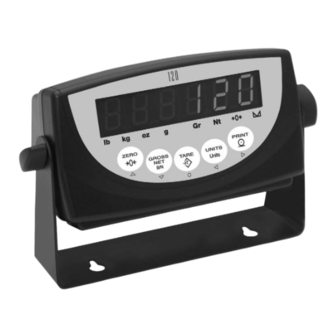
Overview The 120 Indicator is a single-channel digital weight indicator housed in a durable plastic enclosure. The indicator front panel consists of a large (.8 in, 20 mm), six-digit, seven-segment LED display and five-button keypad. Features include: • Drives up to four 350or eight 700 load cells •... -
Page 8: Operating Modes
Section 1.5 on page 9 to indicate scale status and the type of weight value displayed. When configuration is complete and a legal seal is affixed to the back of the indicator, this is the only mode the 120 Indicator can operate in. -
Page 9: Led Annunciators
LED Annunciators The 120 Indicator display uses eight LED annunciators to provide additional information about the value being displayed: • Gr (gross) and Nt (net) annunciators are lit to show whether the displayed weight is a gross or net weight. -
Page 10: Indicator Operations
120 Digital Weight Indicator Indicator Operations Use the following instruction for basic operation of the 120 Indicator. 1.6.1 Weighing Mode Operations Operation instructions when in the weighing mode. Toggle Gross/Net Mode Press the GROSS/NET key to switch the display mode from gross to net, or from net to gross. If a tare value has been entered or acquired, the net value is the gross weight minus the tare. -
Page 11: Installation
• 9V power supply adapter (PN 78611 for 115 VAC units, PN 78612 for 230 VAC units) Enclosure and Connectors The back of the 120 Indicator enclosure provides a 3-pin power connection, 9-pin D-sub connector for communications, and an available 6-pin connector or load cell cord grip connector for load cell connection (see Figure 2-1). -
Page 12: Load Cells
120 Digital Weight Indicator Port 1 Pin Port Function Printer RS-232 TxD RS-232 TxD RS-232 RxD — not used EDP/Printer RS-232 Ground / –20 mA OUT not used Printer +20 mA OUT Table 2-1. Serial Connector (Port 1) Pin Assignments 2.3.1... -
Page 13: Enclosure Disassembly
Rubber foot 83428 Tilt stand wing knob 78949 Optional wall-mount tilt stand 78611 9V power supply adapter for 115V units 78612 9V power supply adapter for 230V units Table 2-4. Replacement Parts © Rice Lake Weighing Systems ● All Rights Reserved... -
Page 14: Configuration
Configuration Methods The 120 Indicator can be configured by using the front panel keys to navigate through a series of configuration menus or by sending commands or configuration data to the EDP port. Configuration using the menus is described in Section 3.1.3. -
Page 15: Edp Command Configuration
EDP command set. 3.1.3 Front Panel Configuration The 120 Indicator can be configured using a series of menus accessed through the indicator front panel when the indicator is in setup mode. Table 3-1 summarizes the functions of each of the main menus. -
Page 16: Menu Structures And Parameter Descriptions
Menu Structures and Parameter Descriptions The following sections provide graphic representations of the 120 Indicator menu structures. In the actual menu structure, the settings you choose under each parameter are arranged horizontally. To save page space, menu choices are shown in vertical columns. - Page 17 (DFSENS parameter) fall outside of this threshold, digital filtering is suspended. If NONE is selected, the filter is always enabled. 0.2DD 0.5DD 10DD 20DD 50DD 100DD 200DD 250DD Table 3-2. Configuration Menu Parameters © Rice Lake Weighing Systems ● All Rights Reserved...
-
Page 18: Format Menu
120 Digital Weight Indicator 3.2.2 Format Menu PROGRM PFORMT CONFIG FORMAT CALIBR SERIAL TIME DATE VERS PRIMAR SECNDR DSPRAT MULEXP DECPNT DSPDIV UNITS DECPNT DSPDIV UNITS MUL T 250MS 500MS 88888. 8 dec_position 750MS 888888 0.45359 8.88888 number 1SEC 888888 88.8888... - Page 19 Multiplier decimal shift. Specifies a divisor used to shift the decimal position in the secondary units multiplier value. Use the left and right arrow keys to shift the decimal point within the displayed MULT value. Table 3-3. Format Menu Parameters (Continued) © Rice Lake Weighing Systems ● All Rights Reserved...
-
Page 20: Calibration Menu
120 Digital Weight Indicator 3.2.3 Calibration Menu See Section 4.0 on page 26 for calibration procedures. PROGRM PFORMT CONFIG FORMAT CALIBR SERIAL TIME DATE VERS WZERO WVAL WSPAN REZERO *CAL* CAL* *CAL* 10000 Display and edit Press Enter to Display and edit... -
Page 21: Serial Menu
Configuration 3.2.4 Serial Menu See Section 7.2 on page 33 for information about the 120 Indicator serial data format. PROGRM PFORMT CONFIG FORMAT CALIBR SERIAL TIME DATE VERS PRINT BAUD BITS TERM BAUD BITS TERM ECHO 9600 8NONE 9600 8NONE... - Page 22 Description STREAM Selects the serial port used for continuous transmission. See Section 7.2 on page 33 for information about the 120 Indicator continuous data format. STMDLY 250MS Stream delay. Specifies the delay, seconds (SEC) or milliseconds (MS), inserted between stream frames.
-
Page 23: Program Menu
CONSTU or CONSNU immediately resets the consecutive number used for printing. CONSTU Consecutive number start up value. Specifies the initial consecutive number (CONSNU) value used when the number indicator is powered on. Table 3-6. Program Menu Parameters © Rice Lake Weighing Systems ● All Rights Reserved... -
Page 24: Print Format Menu
120 Digital Weight Indicator 3.2.6 Print Format Menu Section 6.0 on page 31 for information about custom print formatting. PROGRM PFORMT CONFIG FORMAT CALIBR SERIAL TIME DATE VERS EDIT INSERT DELETE 00_@40 0 1 _ N 4 E x x _ _ 0 0... -
Page 25: Date Menu
Version menu: when selected, the indicator displays the installed software version number. and the indicator model PROGRM PFORMT CONFIG FORMAT CALIBR SERIAL TIME DATE VERS Software version Figure 3-11. Version Menu © Rice Lake Weighing Systems ● All Rights Reserved... -
Page 26: Calibration
120 Digital Weight Indicator Calibration The 120 Indicator can be calibrated using the front panel, EDP commands, or the Revolution® configuration utility. Each method consists of the following steps: • Zero calibration • Entering the test weight value • Span calibration •... -
Page 27: Edp Commands
EDP Commands The 120 Indicator can be controlled by a personal computer or remote keyboard connected to the indicator EDP port. Control is provided by a set of EDP commands that can simulate front panel key press functions, display and change setup parameters, and perform reporting functions. -
Page 28: Parameter Setting Commands
120 Digital Weight Indicator 5.1.4 Parameter Setting Commands Parameter setting commands allow you to display or change the current value for a particular configuration parameter (Tables 5-3 through 5-8). Current configuration parameter settings can be displayed in either configuration mode or normal mode using the following syntax: command<ENTER>... - Page 29 Table 5-7. PROGRM EDP Commands Command Description Values WWPF Print characters of format string Section 6.0 on page 31 for detailed information Print hex values of format string Table 5-8. PFORMT EDP Commands © Rice Lake Weighing Systems ● All Rights Reserved...
-
Page 30: Saving And Transferring Data
Saving and Transferring Data Connecting a personal computer to the 120 Indicator EDP port allows you to save indicator configuration data to the PC or to download configuration data from the PC to an indicator. The following sections describe the procedures for these save and transfer operations. -
Page 31: Print Formatting
Print Formatting Print Formatting The 120 Indicator print format can be edited to specify the format of the printed output when the PRINT key is pressed or when a KPRINT EDP command is received. Each print format can be customized to include up to 300 characters of information, such as company name and address, on ®... -
Page 32: Using The Front Panel
NOTE: Some characters cannot be displayed on the 120 Indicator front panel (see the ASCII character chart on page 35) and are shown as blanks. The 120 Indicator can send or receive any ASCII character; the character printed depends on the particular ASCII character set implemented for the receiving device. -
Page 33: Appendix
Continuous Output (Stream) Format Figure 7-1 shows the continuous output format sent to the 120 Indicator EDP or printer port when the STREAM parameter (SERIAL menu) is set to either EDP or PRN. <STX> <POL> <wwwwwww> <UNIT> <G/N> <S> <EXTEND> <TERM>... -
Page 34: Front Panel Display Characters
120 Digital Weight Indicator Front Panel Display Characters Figure 7-2 shows the 7-segment LED character set used to display alphanumeric characters on the 120 Indicator front panel. 120 Indicator Figure 7-2. Display Characters www.RiceLake.com Visit our website... -
Page 35: Ascii Character Chart
ASCII Character Chart Use the decimal values for ASCII characters listed in Tables 7-2 and 7-3 when specifying print format strings on the 120 Indicator PFORMT menu. The actual character printed depends on the character mapping used by the output device. - Page 36 120 Digital Weight Indicator ASCII ASCII ASCII ASCII Ç á ü í é ó â ú ä ñ à Ñ å ª ç º ê ¿ ë è ¬ ï î ¥ ì ¡ Ä « Î Å » Ç...
-
Page 37: Conversion Factors For Secondary Units
Appendix Conversion Factors for Secondary Units The 120 Indicator has the capability to mathematically convert a weight into many different types of units and instantly display those results with a press of the UNITS key. Secondary units can be specified on the FORMAT menu using the SECNDR parameter, or by using EDP commands. -
Page 38: Digital Filtering
Digital Filtering The 120 Indicator uses averaged digital filtering to reduce the effect of vibration on weight readings. Adjustable threshold and sensitivity functions allow quick settling by suspending filter averaging, allowing the weight reading to jump to the new value. -
Page 39: Test Mode
Appendix Test Mode In addition to normal and setup modes, test mode provides a number of diagnostic functions for the 120 Indicator, including: • Display raw A/D count • Display digital filter raw counts • Reset configuration parameters to default values •... -
Page 40: 8.0 Specifications
120 Digital Weight Indicator 8.0 Specifications Power Both Ports 7 or 8 data bits; even, odd, space, or no parity Line Voltages 115 or 230 VAC Operator Interface Frequency 50 or 60 Hz Display 6-digit LED display. 7-segment, 0.8 in (20 mm) - Page 42 © Rice Lake Weighing Systems Content subject to change without notice. 230 W. Coleman St. • Rice Lake, WI 54868 • USA USA: 800-472-6703 • International: +1-715-234-9171 December 1, 2023 PN 76699 Rev C www.ricelake.com...
Need help?
Do you have a question about the 120 and is the answer not in the manual?
Questions and answers