
Subscribe to Our Youtube Channel
Related Manuals for ADLINK Technology ROScube-Pico TGL RQP-T37


Summary of Contents for ADLINK Technology ROScube-Pico TGL RQP-T37
- Page 1 ROScube-Pico TGL User’s Manual Embedded Real-Time Robotic Controller with 11th Gen Intel® Core ™ Processor Manual Rev.: Revision Date: January 18, 2022 Part Number: 50M-00059-1000 Leading EDGE COMPUTING...
- Page 2 Preface Copyright Copyright © 2022 ADLINK Technology, Inc. This document contains proprietary information protected by copyright. All rights are reserved. No part of this manual allow to reproduce by any mechanical, electronic, or other means in any form without prior written permission of the manufacturer.
-
Page 3: Table Of Contents
Table of Contents Preface ..........................ii Table of Contents......................iii List of Figures ........................v List of Tables........................vi Introduction........................1 Specifications ......................3 2.1. Product Specifications ....................3 2.2. Packing List ........................4 2.3. Optional Accessories ....................4 2.4. Mechanical Layout......................5 2.5. Mechanical Dimensions....................5 2.6. System Layout ......................6 Pinouts and Signal Descriptions................9 3.1. -
Page 4: Preface
Safety Instructions......................37 Getting Service.........................38 Preface... -
Page 5: List Of Figures
List of Figures Figure 1: ROScube-Pico TGL Mechanical Dimensions ................5 Figure 2 -Carrier Board Connectors (top)....................6 Figure 4: Front Panel I/O ..........................7 Figure 5: Right Side Panel I/O........................7 Figure 6: Rear Side Panel I/O ........................8 Figure 7: LAN Port LEDs ..........................9 Figure 7: HDMI Connector........................ - Page 6 List of Tables Table 1: Carrier Board Connector Legend (top)..................6 Table 3: Front Panel I/O Legend ......................7 Table 4: Right Side Panel I/O ........................7 Table 5: Rear Side Panel I/O ........................8 Table 5: LAN Port LED Behaviour......................9 Table 6: HDMI Connector Pin definition ....................10 Table 7: DisplayPort Connector Pin definition..................
-
Page 7: Introduction
1. Introduction ADLINK’s ROScube Pico TGL is a real-time ROS 2 enabled robotic controller based on the 11th Gen Intel® Core™ i7/i5/i3 processor with Intel® Iris® Xe Graphics, featuring exceptional I/O connectivity and supporting a wide variety of sensors and actuators for unlimited robotic applications. The ROScube Pico TGL supports the full complement of resources provided by ADLINK Neuron SDK, the perfect platform for development of industrial use service robotic applications such as autonomous mobile robots (AMR) and autonomous mobile industrial robots (AMIR) Introduction... - Page 8 This page intentionally left blank. Introduction...
-
Page 9: Specifications
2. Specifications 2.1. Product Specifications Model RQP-T37 RQP-T35 RQP-T33 Intel® Core™ i7-1185G7E Intel® Core™ i5-1145G7E Intel® Core™ i3-1115G4E Processor Cores Threads Base Freq. 1.8GHz @ 15W 1.5GHz @ 15W 2.2GHz @ 15W Max. Turbo Freq. 4.4GHz 4.1GHz 3.9GHz Memory 2x 16GB DDR4 3200MHz 2x 8GB DDR4 3200MHz 2x 4GB DDR4 3200MHz M.2 M Key... -
Page 10: Packing List
Power Requirements DC Power Input 12-19VDC (±5% tolerance, reverse polarity protection) Power Consumption 60.5W AC/DC Power Adapter 90W AC/DC power adapter (optional, see ordering information) Mechanical Dimensions (WxDxH) 140 x 110 x 63 mm (5.5 x 4.33 x 2.48 inches) Weight 1,086 g Mounting... -
Page 11: Mechanical Layout
2.4. Mechanical Layout 2.5. Mechanical Dimensions 180.00 161.60 140.00 Dimensions: mm Figure 1: ROScube-Pico TGL Mechanical Dimensions Specifications... -
Page 12: System Layout
2.6. System Layout 2.6.1. Carrier Board Connector Locations Figure 2 -Carrier Board Connectors (top) M.2 Key-M socket for NVMe SSD (Top, M2_M1) M.2 Key-E socket for M.2 2230 Wi-Fi card (Bottom, M2_E1) USB 2.0 connector (USB2_7_8) COM port header (to RS-232 “COM 1” on right side I/O) Clear CMOS jumper (CLRCMOS1) Power mode jumper (SIO_AT1) (open: ATX;... -
Page 13: Figure 4: Front Panel I/O
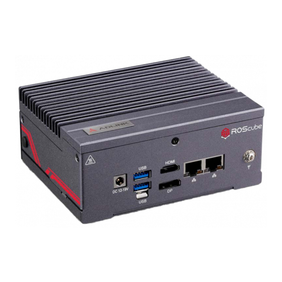
2.6.2. External Connector Locations Figure 3: Front Panel I/O DC power input, 12-19V DC-in jack 1x DisplayPort 1.4 2x USB 3.2 Gen2 Type A ports 1x 1GbE (LAN1) with lockable connectors HDMI connector 1x 2.5GbE (LAN2) Table 2: Front Panel I/O Legend Figure 4: Right Side Panel I/O RS-232 (“COM 1”) System Management Header... -
Page 14: Figure 6: Rear Side Panel I/O
Figure 5: Rear Side Panel I/O 2x USB 3.2 Gen2 Type C ports 2 x USB 3.2 Gen2 Type A with lockable connectors 1x headphone/microphone jack Table 4: Rear Side Panel I/O Specifications... -
Page 15: Pinouts And Signal Descriptions
3. Pinouts and Signal Descriptions 3.1. Gigabit Ethernet Ports There are two Gigabit Ethernet ports on the front panel. Please refer to the table below for the LAN port LED behaviour. LAN1/2 port LED behavior is as below: Figure 6: LAN Port LEDs Activity/Link LED Speed LED Status... -
Page 16: Hdmi
3.2. HDMI The ROSCube Pico provides one external HDMI port for connection to an external monitor. Figure 7: HDMI Connector Signal Signal HDMI1_D2_CN_P HDMI1_CK_CN_N HDMI1_D2_CN_N HDMI1_CN_CEC HDMI1_D1_CN_P HDMI1_CN_SCL HDMI1_D1_CN_N HDMI1_CN_SDA HDMI1_D0_CN_P +V5P0_HDMI HDMI1_D0_CN_N HDMI1_CN_HPD HDMI1_CK_CN_P Table 6: HDMI Connector Pin definition Pinouts and Signal Descriptions... -
Page 17: Displayport Connector
3.3. DisplayPort Connector The DisplayPort connector on the front panel can also connect to VGA, DVI, and HDMI displays via DisplayPort to VGA adapter cable, DisplayPort to DVI adapter cable, or DisplayPort to HDMI adapter cable. Figure 8: DisplayPort Connector Signal Signal CN_DDPx0+... -
Page 18: Rs-232 Serial Port Header (Com 1)
3.6. RS-232 Serial Port Header (COM 1) There is a RS232 DB9 port on the right side panel (labeled “COM1”). Figure 9: RS-232 DB9 Serial Port Signal Signal DDCD#1 DDSR#1 RRXD1 RRTS#1 TTXD1 CCTS#1 DDTR#1 RRI#1 Table 8: RS-232 Serial Port Pin Definition Pinouts and Signal Descriptions... -
Page 19: System Management Header (Com 2)
3.7. System Management Header (COM 2) There is a DB9 port with proprietary pinout on the right side panel for system management (labeled “COM 2”). Figure 10: System Management Header Signal Signal HDLED+ PWRBTN# PLED+ RESET# HOLED- PLED- Table 9: System Management Header Pin definition PWRBTN: Power Switch •... -
Page 20: Expansion Slots
3.8. M.2 Expansion Slots There are 2 internal M.2 slots on the motherboard. Refer to 2.6.1Carrier Board Connector Locations on page 6 for their locations. 3.8.1. M.2 for SSD M.2 (Key M, 2242/2260/2280*) with PCIe x4 Gen4 and SATA 6Gb/s for SSD. (*M.2 Key M 2280 supported by bracket) Signal Signal... -
Page 21: Table 11: M.2 Key-E Socket (M2_E1)
3.8.2. M.2 for Wi-Fi/Bluetooth M.2 (Key E, 2230) with PCIe x1, USB 2.0 and CNVi for wireless Signal Signal +3.3V USB_D+ +3.3V USB_D- CNV_WGR_D1- CNV_RF_RESET CNV_WGR_D1+ MODEM_CLKREQ CNV_WGR_D0- CNV_WGR_D0+ CNV_WGR_CLK- CNV_BRI_RSP CNV_WGR_CLK+ CNV_BGI_DT PETp CNV_RGI_RSP PETn CNV_BRI_DT PERp PERn PEFCLKp PEFCLKn SUSCLK CLKREQ#... -
Page 22: Jumpers
3.9. Jumpers Refer to 2.6.1Carrier Board Connector Locations on page 6 3.9.1. Clear CMOS Jumper Default Clear CMOS Figure 11: Clear CMOS Jumper (CLRCMOS1) The jumper CLRCMOS1 allows you to clear the data in CMOS. To clear and reset the system parameters to default values, please turn off the computer and unplug the power cord from the power supply. -
Page 23: Onboard Headers
3.10. Onboard Headers Refer to 2.6.1 Carrier Board Connector Locations on page 6 for onboard header locations. Header Pin Definition Function USB 2.0 Pin Header 9-pin USB 2.0 header (USB2_7_8) DUMMY COM1 Pin Header RS-232 COM1 port header RRXD 1 DDTR# 1 DDSR# 1 CCTS # 1... - Page 24 This page intentionally left blank. Pinouts and Signal Descriptions...
-
Page 25: Getting Started
4. Getting Started The chapter describes the steps needed to install optional expansion modules onto ROScube Pico series and begin using it in your application. 4.1. Connect the DC plug adapter cable Locate the DC plug adapter cable, included in the accessory box (shown below). Insert to the DC output wires of the AC adapter into the terminal block P1 as indicated: negative (black) to “-“... - Page 26 Mount the device to a wall using the or mounting holes or keyhole openings indicated below, according to the spacing dimensions of the holes in the bracket as shown. All dimensions shown in millimeters 161.60 80.80 Getting Started...
-
Page 27: Uefi Setup
5. UEFI setup 5.1. Introduction The Unified Extensible Firmware Interface (UEFI) is a program that provides a basic level of communication between the processor and peripherals. In addition, the UEFI also contains codes for various advanced features applied to the ROScube-Pico TGL Series. The UEFI setup program includes menus for configuring settings and enabling features of the ROScube-Pico TGL Series. -
Page 28: Main Screen
5.2. Main Screen When you enter the UEFI SETUP UTILITY, the Main screen will appear and display the system overview. 5.3. Advanced Screen In this section, you may set the configurations for the following items: CPU Configuration, Chipset Configuration, Storage Configuration, NVMe Configuration, Super IO Configuration, ACPI Configuration, USB Configuration and Trusted Computing. - Page 29 5.3.1. CPU Configuration Intel Hyper Threading Technology This feature, requires an Intel processor that supports Hyper-Threading technology and an operating system that includes optimization for this technology, such as Microsoft® Windows® 10 64-bit, 8.1 64-bit, 7 32-bit, 7 64-bit. Set to [Enabled] if using Microsoft®...
- Page 30 5.3.2. Chipset Configuration VT-d Use this to enable or disable Intel® VT-d technology (Intel® Virtualization Technology for Directed I/O). The default value of this feature is [Disabled]. Share Memory Configure the size of memory that is allocated to the integrated graphics processor when the system boots up. Onboard LAN1 This allows you to enable or disable the Onboard LAN1 feature.
- Page 31 5.3.3. Storage Configuration SATA Controller(s) Use this item to enable or disable the SATA Controller feature. SATA Mode Selection Use this to select SATA mode. The default value is [AHCI Mode]. AHCI (Advanced Host Controller Interface) supports NCQ and other new features that will improve SATA disk performance but IDE mode does not have these advantages.
- Page 32 5.3.4. NVMe Configuration Displays NVMe controller and drive Information. 5.3.5. Super IO Configuration COM1 Configuration Use this to set parameters of COM1. UEFI setup...
- Page 33 WDT Timeout Reset Use this to set the Watch Dog Timer. 5.3.6. AMT Configuration AMT BIOS Features When disabled, AMT BIOS Features are no longer supported and the user is no longer able to access MEBx Setup. USB Provisioning of AMT Enable or disable AMT USB Provisioning.
- Page 34 Secure Erase Configuration Secure Erase Configuration menu: (1) Change Secure Erase module behavior by switching to Simulated mode (this performs SE flow without erasing the SSD), or switching to Real mode (erases SSD); (2) Force Secure Erase on next boot by enabling this function. OEM Flags Settings This can configure OEM Flags.
- Page 35 5.3.7. ACPI Configuration Suspend to RAM Use this item to select whether to auto-detect or disable the Suspend-to- RAM feature. Select [Auto] will enable this feature if the OS supports it. Onboard LAN Power On Use this item to enable or disable onboard LAN to turn on the system from the power-soft-off mode. RTC Alarm Power On Use this item to enable or disable RTC (Real Time Clock) to power on the system.
- Page 36 5.3.8. USB Configuration Legacy USB Support Enable or disable Legacy OS Support for USB 2.0 devices. If you encounter USB compatibility issues it is recommended to disable legacy USB support. Select UEFI Setup Only to support USB devices under the UEFI setup and Windows/Linux operating systems only.
- Page 37 5.3.9. Trusted Computing Security Device Support Enable or disable BIOS support for security device. UEFI setup...
- Page 38 5.3.10. Instant Flash Instant Flash is a UEFI flash utility embedded in Flash ROM. This convenient UEFI update tool allows you to update the system UEFI BIOS without first entering the operating system. Just launch this tool and save the new UEFI file to your USB flash drive, or hard drive to update your UEFI.
-
Page 39: Hardware Health Event Monitoring Screen
5.4. Hardware Health Event Monitoring Screen In this section, it allows you to monitor the status of the hardware on your system, including the parameters of the CPU temperature, motherboard temperature, CPU fan speed, chassis fan speed, and the critical voltage. 5.4.1. -
Page 40: Security Screen
5.5. Security Screen In this section, you may set, change or clear the supervisor/user password for the system. Supervisor Password Set or change the password for the administrator account. Only the administrator has authority to change the settings in the UEFI Setup Utility. Leave it blank and press enter to remove the password. User Password Set or change the password for the user account. -
Page 41: Boot Screen
5.6. Boot Screen In this section, it will display the available devices on your system for you to configure the boot settings and the boot priority. Boot From Onboard LAN Use this item to enable or disable the Boot From Onboard LAN feature. Setup Prompt Timeout This shows the number of seconds to wait for setup activation key. -
Page 42: Exit Screen
5.7. Exit Screen Save Changes and Exit When you select this option, it will pop-out the following message, “Save configuration changes and exit setup?” Select [OK] to save the changes and exit the UEFI SETUP UTILITY. Discard Changes and Exit When you select this option, it will pop-out the following message, “Discard changes and exit setup?”... - Page 43 Safety Instructions Read and follow all instructions marked on the product and in the documentation before you operate your system. Retain all safety and operating instructions for future use. • Please read these safety instructions carefully. • Please keep this User‘s Manual for later reference. •...
- Page 44 5215 Hellyer Avenue, #110, San Jose, CA 95138, USA Tel: +1-408-360-0200 Toll Free: +1-800-966-5200 (USA only) Fax: +1-408-360-0222 Email: info@adlinktech.com ADLINK Technology (China) Co., Ltd. Address: 300 Fang Chun Rd., Zhangjiang Hi-Tech Park, Pudong New Area Shanghai, 201203 China Tel: +86-21-5132-8988 Fax: +86-21-5132-3588 Email: market@adlinktech.com...
Need help?
Do you have a question about the ROScube-Pico TGL RQP-T37 and is the answer not in the manual?
Questions and answers