Table of Contents
Advertisement
Quick Links
Download this manual
See also:
User Manual
Advertisement
Table of Contents

Related Manuals for ADLINK Technology cPCI-7252


Summary of Contents for ADLINK Technology cPCI-7252
- Page 1 PCI-7250/7251 Relay Actuator & Isolated D/I Cards...
- Page 2 Trademarks ® ® NuDAQ , NuIPC , cPCI-7252 and PCI-7250/7251 are registered trademarks of ADLink Inc. Other product names mentioned herein are used for identification purposes only and may be trademarks and/or registered trademarks of their respective companies.
-
Page 4: Table Of Contents
AYOUT ..............10 NPUT IGNAL ETTING ............11 ONNECTOR SSIGNMENTS 2.6.1 PCI-7250/51 Pin assignments ............11 2.6.2 cPCI-7252 Pin assignments ............12 PCI-7250 PCI-7251 C ..........13 ONNECTION CHAPTER 3 REGISTER FORMAT ............15 I/O P ..............15 DDRESS ..........16... - Page 5 5.2 R (7250UTIL.EXE) ........23 UNNING ESTING TILITY 5.3 S ..........23 OFTWARE RIVER AMING ONVENTION _7250_I /_7252_I ............24 NITIAL NITIAL _7250_DI, _7252_DI ..............25 _7250_DO, _7252_DO ..............26 _7250_DO_R , _7252_DO_R ......27 ELAY _7251_C ..............28 HECK XIST CHAPTER 6 TROUBLESHOOTING ............
-
Page 6: How To Use This Guide
How to Use This Guide In the following contents, we use PCI-725X as a convenient for PCI- 7250, PCI-7251 and cPCI-7252 if no specifed. The manual describes how to modify various settings on the PCI-725X cards to meet your requirements. It is divided into five chapters: •... -
Page 8: Chapter 1 Introduction
This PCI-7250 and PCI-7251 provide 8 relay actuators and 8 opto- isolated digital inputs. From the eight relays, four relays are Form C (R0~R3) and four relays are Form A ( R4~R7). The cPCI-7252 provides 8 relay actuators and 16 opto-isolated digital inputs, all relays are Form C type. -
Page 9: Features
The PCI-7250 Relay Actuator and D/I Card provides the following advanced features: • 32-bit PCI-Bus, Plug and Play for PCI-7250 • ® 32-bit ComapctPCI Bus, Plug and Play for cPCI-7252 • 8 relay actuator outputs • 8 opto-isolated digital inputs for PCI-7250 • 16 opto-isolated digital inputs for cPCI-7252 •... - Page 10 + 5V from the PCI-Bus ♦ General Specifications Dimensions 147 mm x 95 mm for PCI-7250 141 mm x 106 mm for PCI-7251 160 mm x 100 mm for cPCI-7252 32-bit PCI bus I/O port address Assigned By System BIOS Temperature 0 ~ 50°...
-
Page 12: Chapter 2 Installation
2.1 What You Have In addition to this User‘s Manual , the package includes the following items: • PCI-7250 (or PCI-7251, cPCI-7252) Relay Actuator & Isolated D/I Card • Manual & Software Utility CD-ROM Disk ( for PCI-7250 and cPCI-7252 only) If any of these items is missing or damaged, contact the dealer from whom you purchased the product. -
Page 13: Device Installation For Windows 95
You are now ready to install your 7250 series products. 2.3 Device Installation for Windows 95 While you first plug PCI-7250 or cPCI-7252 card and enter Windows 95, the system will detect this device automatically and show the following dialog box that prompts you to select the device information source. - Page 14 “Pci7250.inf”) in the input field (X indicates the CD ROM drive) and then click OK. The system will start the installation of PCI- 7250. For cPCI-7252, please get the software driver from “X:\Win95Inf\7252” subdirectory. Installation • • 7...
-
Page 15: Pcb Layout
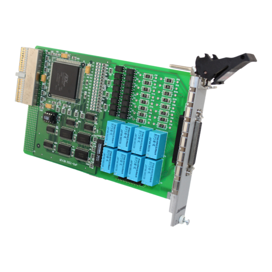
2.4 PCB Layout 2.4.1. PCI-7250’ PCB Layout Controller Figure 2.1 PCI-7250 Layout 8 • • Installation... - Page 16 2.4.2. cPCI-7252’ PCB Layout cPCI Installation • • 9...
-
Page 17: Input Signal Setting
2.5 Input Signal Setting (This section is for PCI-7250 and PCI-7251 only.) For PCI7250 and PCI-7251, there are 8 jumpers (JP1 to JP8) associated with each digital input channel for configuring the channel as AC-Filter or Non-AC-Filter input. Each digital input channel and their corresponding jumper are shown in the following Table 2.1. -
Page 18: Connector Pin Assignments
2.6 Connector Pin Assignments 2.6.1 PCI-7250/51 Pin assignments The PCI-7250 card comes equipped with a 37-pin D type connector (CN1) accessible from the rear of the card ( Ref. Fig 2.1). The pin assignment of the D type connector is described by Figure 2.2. COM0 COM3 COM1... -
Page 19: Cpci-7252 Pin Assignments
COM4 COM1 19 COM5 COM2 24 COM6 COM3 25 COM7 Figure 2.3 Pin Assignment of cPCI-7252 CN1 Legend : 1. DIn -digital input channel n 2. IGND - ground of DIn signals 2. DInH -digital input channel n with positive polarity 3. -
Page 20: Pci-7250 And Pci-7251 Connection
2.7 PCI-7250 and PCI-7251 Connection There are 8 relay output and 8 isolation input on both PCI-7250 and PCI-7251. The PCI-7251 is used as expansion of the PCI-7250. The operations of PCI-7251 are the same as which in PCI-7250. There are at most 3 PCI-7251 expansion boards to attach on the PCI-7250. -
Page 22: Chapter 3 Register Format
The I/O operations are also included. 3.1 I/O Port Base Address The PCI-7250 or cPCI-7252 functions as a 32-bit PCI target device to any master on the PCI bus. There are three types of registers on the PCI-725X: PCI Configuration Registers (PCR), Local Configuration Registers (LCR) and PCI-725X registers. -
Page 23: Control And Status Registers Map
Table 3.1 The register offset and the functions 3.3 Relay Output and Readback Registers There are 8 relays on each PCI-7250 / 7251 and cPCI-7252 board. Each relay are controlled by one bits of the control register. The bit value ‘0’ means the relay is not excited. The normal open signal line is ‘open’... -
Page 24: Isolation Input Registers
The bit value “1” means input voltage is high and “0” menas input voltage is low. Data Format : Relay Output : Iso. Input Iso. Input DI15 DI14 DI13 DI12 DI11 DI10 (Note: bit#8~15 is for cPCI-7252 only) Register Format • • 17... -
Page 25: Chapter 4 Operation Theorem
The PCI-7250 contains two types of relay : Form C and Form A. The relay R0 ~ R3 are form C relays, and R4 ~ R7 are plain form A type. Note that the cPCI-7252 contains Form C relay only. The difference between these two types of relay are : 1. -
Page 26: Using Isolated Input
Control Bit = High (1) Control Bit = Low (0) Form A relay only has two contacts : NC (Normal Close) and COM (Common). The COM post can make contact either NO post or not contact NO post. When the control bit is high (1), the COM post and NO post are contacted. - Page 27 DC voltage. The cPCI-7252 contains 16 identical opto-isolated control input channels. The circuit diagram of the isolated input signales of channel number 8~15 are the same as which in PCI-7250. However, the input signals for channel number 0~7 is differential input which is shown in the following diagram.
-
Page 28: Chapter 5 C/C++ Libraries
C/C++ Libraries In this chapter, the PCI-7250's software drivers : C/C++ language libraries for DOS and Windows 95 are described. 5.1 Installation 5.1.1 Installation The PCI-7250's Software Library supplied with PCI-7250 includes a utility software, C-language library, DLL libraries and some demonstration programs which can help you reduce programming work. - Page 29 X:\NuDAQPCI\7250\Win95\Setup.exe in the Run dialog box. (X indicates the CD ROM driver). For cPCI-7252, please type X:\NuIPC\7252\Win95\Setup.exe in the Run dialog box. (X indicates the CD ROM driver). Setup first displays a Welcome dialog box. Please click Next button to go on installation.
-
Page 30: Running Testing Utility (7250Util.exe)
In DOS Environment : _{hardware_model}_{action_name}. e.g. _725X_Initial (). (where “725X” is “7250” for PCI-7250 and “7252” for cPCI-7252.) In order to recognize the difference between DOS library and Windows 95 library, A capital "W" is put on the head of each function name of the Windows 95 DLL driver. -
Page 31: Nitial /_7252_I Nitial
5.4 _7250_Initial/_7252_Initial @ Description The PCI-7250 and cPCI-7252 cards are initialized according to the card number. Because the PCI-7250 is PCI bus architecture and meets the plug and play design, the IRQ and base_address ( pass-through address) are assigned by system BIOS directly. -
Page 32: 7250_Di
: card number to select borad diPortNo : Digital Input Channel No, the constant is (Note: This argument is not necessary for cPCI-7252) DI_PORT0 0x00 Access the 8 Digital Input of PCI-7250 DI_PORT1 0x01 Access the 8 Digital Input of... -
Page 33: 7250_Do
@ Argument cardNo : card number to select borad doChannelNo : Digital Output Channel No, the constant is (Note: This argument is not necessary for cPCI-7252) DI_PORT0 0x00 Access the 8 Digital Input of PCI-7250 DI_PORT1 0x01 Access the 8 Digital Input of... -
Page 34: 7250_Do_Read_Back, _7252_Do_Readrelay
This function is used to read-back data from digital output port which is control by 725X_DO function. There are 8-bit digital outputs on the PCI-7250, cPCI-7252, or PCI-7251 extended board. You can get back all RELAYs status ( ON or OFF) by using this function. -
Page 35: 7251_C Heck
5.8 _7251_Check_Exist @ Description This function is used to check the exist of PCI-7251 expanded board. For normal configuration, each PCI-7250 can be connected with three expanded PCI-7251 boards. This function can be used to check if each of the PCI-7251 is existed or not. @ Syntax C/C++ (DOS, Windows 95) U16 _7251_Check_Exist (U16 cardNo, U16... -
Page 36: Chapter 6 Troubleshooting
Troubleshooting If your PCI-7250 can not work properly, use the information in this chapter to isolated the problem. You can use the DOS debug program to verify the functionality of your PCI-7250 card. The verification procedures are as follows. Note : Before doing the following procedures, please inspect your PCI- 7250 is not damaged and your computer system is proper operation. - Page 37 30 • • Troubleshooting...
-
Page 38: Appendix A. Relay Contact Protection Circuits
Appendix A. Relay Contact Protection Circuits The contacts are the most important elements of relay constructions, Contact performance conspicuously influenced by contact material, and voltage and current values applied to the contacts. Another important issue is contact protection, a right contact protection circuit can suppress the counter emf to a low level. - Page 39 Device Selection : As a guide in selecting R and C, R : 0.5 to 1 Ω per 1V contact voltage C : 0.5 to 1 µF per 1A contact current Value vary depending on the properties of the capacity C acts to suppress the discharge the moment the contacts open.
- Page 40 Device Selection : Use a zener diode with a zener voltage about the same as the power supply voltage. 4. Varistor Circuit This circuit is also suitable for both AC & DC applications. Using the stable voltage characteristics of the varistor, this circuit prevents excessively high voltages from being applied across the contacts.
-
Page 42: Product Warranty/Service
Product Warranty/Service Seller warrants that equipment furnished will be free form defects in material and workmanship for a period of one year from the confirmed date of purchase of the original buyer and that upon written notice of any such defect, Seller will, at its option, repair or replace the defective item under the terms of this warranty, subject to the provisions and specific exclusions listed herein.
Need help?
Do you have a question about the cPCI-7252 and is the answer not in the manual?
Questions and answers