
Related Manuals for ADLINK Technology PXIe-3987


Summary of Contents for ADLINK Technology PXIe-3987
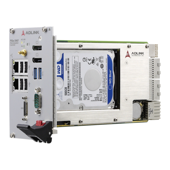
- Page 1 PXIe-3987/3977/3937 PXI Express Embedded Controller User’s Manual Manual Rev.: December 24, 2019 Revision Date: 50-17056-1010 Part No: Leading EDGE COMPUTING...
-
Page 2: Revision History
Leading EDGE COMPUTING Revision History Revision Release Date Description of Change(s) 1.00 2019-10-22 Initial release Add support for Intel® Core™ i5- 2019-12-24 7440EQ/i3-7100E processors; update BIOS and driver sections Revision History... -
Page 3: Preface
PXIe-3987/3977/3937 Preface Copyright © 2019 ADLINK Technology Inc. This document contains proprietary information protected by copy- right. All rights are reserved. No part of this manual may be repro- duced by any mechanical, electronic, or other means in any form without prior written permission of the manufacturer. - Page 4 Leading EDGE COMPUTING California Proposition 65 Warning WARNING: This product can expose you to chemicals including acrylamide, arsenic, benzene, cadmium, Tris(1,3-dichloro-2-propyl)phosphate (TDCPP), 1,4-Diox- ane, formaldehyde, lead, DEHP, styrene, DINP, BBP, PVC, and vinyl materials, which are known to the State of California to cause cancer, and acrylamide, benzene, cadmium, lead, mercury, phthalates, toluene, DEHP, DIDP, DnHP, DBP, BBP, PVC, and vinyl materials, which are known to the State of California to cause...
-
Page 5: Table Of Contents
Package Contents ............. 17 Operating System Installation ..........18 2.2.1 Installation Environment ........... 19 2.2.2 Installing the PXIe-3987/3977/3937 ......20 2.2.3 Replacing the Hard Drive or Solid State Drive ..23 2.2.4 Replacing the Battery Backup ........24 Table of Contents... - Page 6 Leading EDGE COMPUTING 2.2.5 Clearing CMOS............25 3 Driver Installation.............. 27 A Appendix: PXI Trigger I/O Functions .......29 Data Types................. 29 Function Library ..............31 A.2.1 TRIG_Init ..............31 A.2.2 TRIG_Close .............. 31 A.2.3 TRIG_SetSoftTrg ............32 A.2.4 TRIG_Trigger_Route ..........33 A.2.5 TRIG_Trigger_Clear ..........
- Page 7 PXIe-3987/3977/3937 B.5.7 PCI and PCIe Configuration ........53 B.5.8 Advanced Power Management ....... 53 B.5.9 Network Stack Configuration ........54 B.5.10 Hardware Health Configuration ........ 54 B.5.11 PXIe Links Control Configuration ......54 Security................55 B.6.1 Secure Boot.............. 55 Boot ................... 56 B.7.1...
- Page 8 Leading EDGE COMPUTING This page intentionally left blank. viii Table of Contents...
-
Page 9: List Of Figures
PXIe-3987/3977/3937 List of Figures Figure 1-1: Functional Block Diagram..........3 Figure 1-2: Front Panel ..............7 Figure 1-3: PXI Trigger SMB Jack ............. 8 Figure 1-4: DisplayPort Connector............. 9 Figure 1-5: GPIB Connector............. 10 Figure 1-6: LED Indicators ............... 11 Figure 1-7: COM Port............... - Page 10 Leading EDGE COMPUTING This page intentionally left blank. List of Figures...
-
Page 11: List Of Tables
PXIe-3987/3977/3937 List of Tables Table 1-1: Front Panel Legend ............7 Table 1-2: DisplayPort Pin Assignment ..........9 Table 1-3: GPIB Pin Description ............. 10 Table 1-4: LED Indicator Legend ............ 11 Table 1-5: USB 2.0 Port Pin Assignment........12 Table 1-6: Ethernet Port Pin Assignments........ - Page 12 Leading EDGE COMPUTING This page intentionally left blank. List of Tables...
-
Page 13: Introduction
® Combining state-of-the-art Intel Core™ processors and up to 32GB of DDR4 2400MHz memory, the PXIe-3987/3977/3937 uti- lizes multiple computing engines on a single processor, enabling execution of four independent tasks simultaneously. With a config- urable PCIe switch, the PXIe-3987/3977/3937 can support four links x4 or two links x8 x16 PXI Express link capability, with maxi- mum system throughput of up to 16 GB/s (PCI Express 3.0). -
Page 14: Features
PXI-5 PXI Express Hardware Specification Rev.1.0 ® 7th Generation Intel Core™ processors PXIe-3987: Intel® Core™ i7-7820EQ 3.0/3.7 GHz (Turbo), 45W/35W (cTDP, 4C/GT2) PXIe-3977: Intel® Core™ i5-7440EQ 2.9/3.6 GHz (Turbo), 45W/35W (cTDP, 4C/GT2) PXIe-3937: Intel® Core™ i3-7100E 2.9 GHz, ... -
Page 15: Specifications
PXIe-3987/3977/3937 1.2 Specifications Figure 1-1: Functional Block Diagram Processor ® 7th Generation Intel Core™ processor DMI (Direct Media Interface) 3.0 with 8 GT/s bandwidth in each direction Chipset ® Mobile Intel QM175/HM175 chipset Introduction... - Page 16 Supports 2133/2400 MHz RAM up to 32 GB total Supports non-ECC, unbuffered memory The externally accessible SO-DIMM socket can accept replacement DDR4 DRAM DIMM modules. PXIe-3987/3977/3937 specifications and stability guarantees NOTE: NOTE: are only supported when ADLINK-provided DDR4 DRAM SO- DIMM modules are used. Video DisplayPort resolution up to 3840 x 2160 @ 60 Hz ...
- Page 17 PXIe-3987/3977/3937 Trigger I/O One SMB connector on the faceplate to route an external trigger signal to/from PXI trigger bus. Dimensions (3U PXI module) 3U/4-slot PXI standard Weight 1.0 kg (exclusive of packaging) Environmental Condition Range Operating temperature with SSD 0 to 55°C Operating temperature with HDD 0 to 50°C...
- Page 18 ICES-003 Issue 6-2016 AS/NZS CISPR 11: Group 1, Class A emissions AS/NZS CISPR 32: 2015 (Ed 2.0)/C1:2016: Class B The PXIe-3987/3977/3937 meets the essential requirements of applicable European Directives. Power Requirements Typical Consumption DC +3.3V DC +5V...
-
Page 19: I/O And Indicators
PXIe-3987/3977/3937 1.3 I/O and Indicators 1.3.1 Front Panel Figure 1-2: Front Panel GPIB Connector Reset Button (Micro D-Sub 25P) 2X DisplayPort 2X Gigabit Ethernet 2X USB 3.0 PXI Trigger 4X Type-A USB 2.0 LED indicators COM port (D-sub9 serial) Table 1-1: Front Panel Legend... -
Page 20: Figure 1-3: Pxi Trigger Smb Jack
The PXI trigger connector is an SMB jack, used to route external trigger signals to or from the PXI backplane. Trigger signals are TTL-compatible and edge sensitive. The PXIe-3987/3977/3937 provides four trigger routing modes from/to the PXI trigger connec- tor to synchronize PXI modules, including From a selected trigger bus line to PXI trigger connector ... -
Page 21: Figure 1-4: Displayport Connector
PXIe-3987/3977/3937 DisplayPort Connectors Provide monitor connection with installation of requisite adapters required if connecting to VGA/DVI/HDMI monitors. Dual display function is also supported. Figure 1-4: DisplayPort Connector Signal Signal CN_DDPx0+ CN_DDPx3- CN_DDPx0- CN_DDPx_AUX_SEL CN_DDPx1+ CN_DDPx_CONFIG2 CN_DDPx_AUX+ CN_DDPx1- CN_DDPx2+ CN_DDPx_AUX- CN_DDPx_HPD... -
Page 22: Gpib Connector
Leading EDGE COMPUTING 1.3.2 GPIB Connector The GPIB connector is a micro D-sub 25P connector, controlling external bench-top instruments. Connection to other instruments requires the optional ACL-IEEE488-MD1-A cable. The onboard GPIB controller provides: Full compatibility with IEEE 488 standard Up to 1.5 MB/s data transfer rates ... -
Page 23: Reset Button
PXIe-3987/3977/3937 1.3.3 Reset Button The reset button, activated by insertion of any pin-like implement, executes a hard reset for the PXIe-3987/3977/3937. 1.3.4 LED Indicators Three LED indicators on the faceplate indicate operational status of the PXIe-3987/3977/3937, as follows. Figure 1-6: LED Indicators... -
Page 24: Usb 2.0 Ports
Leading EDGE COMPUTING 1.3.5 USB 2.0 Ports The PXIe-3987/3977/3937 provides four USB 2.0 ports via USB Type-A connectors on the faceplate, all compatible with hi-speed, full-speed and low-speed USB devices. Supported boot devices include USB flash drive, USB floppy, USB CD-ROM, and others, with boot priority and device settings configured in BIOS. -
Page 25: Gigabit Ethernet Ports
PXIe-3987/3977/3937 1.3.6 Gigabit Ethernet Ports Dual Gigabit Ethernet connection is provided on the PXIe-3987/ 3977/3937 front panel. 1000Base-T Signal 100/10Base-T Signal MDI0+ MDI0- MDI1+ MDI2+ Reserved MDI2- Reserved MDI1- MDI3+ Reserved MDI3- Reserved Table 1-6: Ethernet Port Pin Assignments Each Ethernet port includes two LED indicators, one Active/Link indicator and one Speed indicator, functioning as follows. -
Page 26: Usb 3.0 Ports
Leading EDGE COMPUTING 1.3.7 USB 3.0 Ports The PXIe-3987/3977/3937 provides two Type-A USB 3.0 ports on the front panel, supporting SuperSpeed, Hi-Speed, full-speed, and low-speed downstream transmission. Multiple boot devices, including USB flash, USB external HD, and USB CD-ROM drives are supported, with boot priority configured in BIOS. -
Page 27: Onboard Connections And Settings
PXIe-3987/3977/3937 1.3.9 Onboard Connections and Settings Figure 1-8: Onboard Configuration Clear CMOS switch SATA connector System battery Table 1-9: Onboard Configuration Legend Introduction... - Page 28 Leading EDGE COMPUTING This page intentionally left blank. Introduction...
-
Page 29: Getting Started
PXIe-3987/3977/3937 Getting Started This chapter describes procedures for installing the PXIe-3987/ 3977/3937 and making preparations for its operation, including hardware and software setup. Note that the PXIe controller is shipped with RAM and an HDD or SSD preinstalled. Contact ADLINK or an authorized dealer if there are any problems during the installation. -
Page 30: Operating System Installation
Leading EDGE COMPUTING 2.2 Operating System Installation For more detailed information about the operating system, refer to the documentation provided by the operating system manufac- turer. Preferred/supported operating systems for the PXIe control- ler are: Windows 10 64-bit For other OS support, contact ADLINK ... -
Page 31: Installation Environment
PXIe-3987/3977/3937 2.2.1 Installation Environment When preparing to install any equipment described in this man- ual, first refer to Important Safety Instructions. Only install equipment in well lit areas on flat, sturdy surfaces with access to basic tools such as flat- and cross-head screw- drivers, preferably with magnetic heads as screws and stand- offs are small and easily misplaced. -
Page 32: Installing The Pxie-3987/3977/3937
Leading EDGE COMPUTING 2.2.2 Installing the PXIe-3987/3977/3937 1. Remove all screw caps (x4). Getting Started... - Page 33 PXIe-3987/3977/3937 2. Release the red locking lever. 3. Depress the latch. 4. Locate the system controller slot of the chassis (Slot 1). Getting Started...
- Page 34 PXIe-3987/3977/3937 into the chassis, as shown. 6. Elevate the latch until the PXIe-3987/3977/3937 is fully seated in the chassis backplane. The alignment pin on the rear of the latch can be threaded into the best fit alignment port in the chassis rail.
-
Page 35: Replacing The Hard Drive Or Solid State Drive
PXIe-3987/3977/3937 2.2.3 Replacing the Hard Drive or Solid State Drive The PXIe controller provides a SATA 3.0 port with a pre-installed 2.5" SATA hard drive or solid state drive. Replacing the HDD or SSD is accomplished as follows. 1. Locate the five screws attaching the hard drive housing to the PXIe controller, as shown. -
Page 36: Replacing The Battery Backup
PXI system. 2.2.4 Replacing the Battery Backup The PXIe-3987/3977/3937 is provided with a 3.0 V “coin cell” lith- ium battery, replacement of which is as follows. 1. Turn off the PXI chassis. 2. Remove the PXIe controller from the chassis. Observe all anti-static precautions. -
Page 37: Clearing Cmos
PXIe-3987/3977/3937 4. Place a fresh identical battery (CR2032 or equivalent) in the socket, ensuring that the positive pole (+) is facing upwards. The battery is most easily seated by first being inserted under the positive retaining clip, and then pushed downward at the negative retaining clip. The bat- tery should easily snap into position. - Page 38 Leading EDGE COMPUTING 4. Remount the controller into the PXI chassis. 5. Press <Delete> or <ESC> to enter BIOS Setup when the splash logo appears. 6. Press <F9> to load optimized defaults in BIOS Setup. 7. Modify the system date and time. 8.
-
Page 39: Driver Installation
Driver Installation Windows 10 already carries most of the device drivers required by the PXIe-3987/3977/3937. Others can be downloaded from the ADLINK website after clicking “Driver” on any of the product pages for this series (the files are exactly the same for each product): www.adlinktech.com/Products/PXI_PXIe/PXIControllers/PXIe-3987... - Page 40 Leading EDGE COMPUTING This page intentionally left blank. Driver Installation...
-
Page 41: A Appendix: Pxi Trigger I/O Functions
Appendix A PXI Trigger I/O Functions This appendix describes use of the PXI trigger I/O function library for the PXIe-3987/3977/3937 controller, to program routing of trig- ger signals between the trigger I/O SMB connector on the face- plate and the PXI trigger bus on the backplane. API files are located in the installation directory of the PXI Trigger I/O driver. - Page 42 Leading EDGE COMPUTING Type Type Description Range C/C++ Pascal Visual Basic (for 32-bit (Delphi) compiler) 32-bit single- -3.402823E38 precision float Single Single floating-point 3.402823E38 1.7976831348 64-bit double- 62315E308 precision double Double Double floating-point 1.7976831348 62315E309 PXI Trigger I/O Functions...
-
Page 43: Function Library
PXIe-3987/3977/3937 A.2 Function Library This section provides detailed definitions of the functions available in the PXIe-3987/3977/3937 function library. Each function includes a description, list of supported cards, syntax, parameter list and Return Code information. A.2.1 TRIG_Init Description Initializes trigger I/O function of PXIe-3987/3977/3937 con- troller. -
Page 44: Trig_Setsofttrg
Leading EDGE COMPUTING Visual Basic TRIG_Close() As Integer Parameter None Return Code ERR_NoError ERR_BoardNoInit A.2.3 TRIG_SetSoftTrg Description Generates a TTL trigger signal to the trigger I/O SMB con- nector on the faceplate or the PXI trigger bus on the back- plane by software command. -
Page 45: Trig_Trigger_Route
PXIe-3987/3977/3937 A.2.4 TRIG_Trigger_Route Description Routes the trigger signal between the trigger I/O SMB con- nector on the faceplate and the PXI trigger bus on the back- plane. This function also allows routing of the software- generated trigger signal to SMB connector or trigger bus. - Page 46 Leading EDGE COMPUTING dest Destination of trigger routing can be one of the following. Available value Description PXI_TRIG_VAL_SMB SMB connector on the faceplate PXI_TRIG_VAL_TRIG0 PXI trigger bus #0 PXI_TRIG_VAL_TRIG1 PXI trigger bus #1 PXI_TRIG_VAL_TRIG2 PXI trigger bus #2 PXI_TRIG_VAL_TRIG3 PXI trigger bus #3 PXI_TRIG_VAL_TRIG4 PXI trigger bus #4 PXI_TRIG_VAL_TRIG5...
-
Page 47: Trig_Trigger_Clear
PXIe-3987/3977/3937 A.2.5 TRIG_Trigger_Clear Description Clears the trigger routing setting. Syntax C/C++ I16 TRIG_Trigger_Clear() Visual Basic TRIG_Trigger_Clear() As Integer Parameters None Return Code ERR_NoError ERR_BoardNoInit ERR_Trigger_Clr A.2.6 TRIG_GetSoftTrg Description Acquires the current software trigger state, with default state after system boot of Logic Low. -
Page 48: Trig_Trigger_Route_Query
Leading EDGE COMPUTING Return Code ERR_NoError ERR_BoardNoInit ERR_Query_Status A.2.7 TRIG_Trigger_Route_Query Description Acquires the current trigger signal routing path. Syntax C/C++ TRIG_Trigger_Route_Query (U32* source, U32* dest, U32* halfway) Visual Basic TRIG_Trigger_Route_Query (source As Long, dest As Long, halfway As Long) As Integer Parameters source Returns to the current source of trigger routing, with possi-... - Page 49 PXIe-3987/3977/3937 dest Returns to the current destination of trigger routing, with possible values including: Available Definition Defined Value PXI_TRIG_VAL_NONE PXI_TRIG_VAL_SMB PXI_TRIG_VAL_TRIG0 PXI_TRIG_VAL_TRIG1 PXI_TRIG_VAL_TRIG2 PXI_TRIG_VAL_TRIG3 PXI_TRIG_VAL_TRIG4 PXI_TRIG_VAL_TRIG5 PXI_TRIG_VAL_TRIG6 PXI_TRIG_VAL_TRIG7 halfway Returns to the current halfway point of trigger routing, with possible values including:...
-
Page 50: Trig_Getdriverrevision
Leading EDGE COMPUTING A.2.8 TRIG_GetDriverRevision Description Acquires the PXI Trigger software driver version; format of the version number is major.minor1.minor2. Syntax C/C++ TRIG_GetDriverRevision(unsigned short *major, unsigned short *minor1, unsigned short *minor2) Visual Basic TRIG_GetDriverRevision (major Integer, minor1 As Integer, minor2 As Integer) As Inte- Parameters major Returns the major version number of the pxi trigger software... -
Page 51: B Appendix: Bios Setup
PXIe-3987/3977/3937 Appendix B BIOS Setup B.1 Entering the BIOS 1. Power on or reboot the PXIe-3987/3977/3937 controller. 2. Press the <Delete> or <Esc> key when the controller beeps. This should be concurrent with the main startup screen. The BIOS setup program loads after a short delay. -
Page 52: Navigation
Leading EDGE COMPUTING B.2 Navigation The BIOS setup utility uses a key-based navigation system called hot keys. Most hot keys can be used at any time during navigation. Key(s) Function Right Arrow, Left Arrow Moves between different setup menus Up Arrow, Down Arrow Moves between options within a setup menu Opens a sub-menu or displays all available settings <Enter>... -
Page 53: Menu Structure
PXIe-3987/3977/3937 B.3 Menu Structure This section presents the primary menus of the BIOS Setup Utility. Use the following table as a quick reference for the contents of the BIOS Setup Utility. The sub-sections that follow provide further details for each top-level menu and sub-menu and the setting options for each menu item. -
Page 54: Main
Leading EDGE COMPUTING B.4 Main The Main Menu provides read-only information about your system and also allows you to set the System Date and Time. Refer to the tables below for details about each section/sub-menu. B.4.1 BIOS Information Feature Options Description BIOS Vendor Info only... -
Page 55: Pch Information
PXIe-3987/3977/3937 B.4.3 PCH Information Feature Options Description Name Info only Displays PCH name PCH SKU Info only Displays PCH SKU Stepping Info only Displays PCH stepping LAN PHY Revision Info only Displays LAN PHY revision ME FW Version Info only... - Page 56 Leading EDGE COMPUTING B.4.4.2 Temperatures Feature Options Description CPU Temperature Current Info only Displays current CPU temperature Startup Info only Displays CPU startup temperature Info only Displays min. CPU temperature Info only Displays max. CPU temperature Board Temperature Current Info only Displays current board temperature Startup Info only...
- Page 57 PXIe-3987/3977/3937 B.4.4.4 Runtime Statistics Feature Options Description Specifies the total time in minutes the Total Runtime Info only system has spent running in S0 state Specifies the time in seconds the system has been running in S0 state, where the...
-
Page 58: System Date And Time
Leading EDGE COMPUTING B.4.4.6 Power Up Feature Options Description Turn on: The machine starts automatically when the power supply is turned on Power-up Mode Remain off: The power button Turn on (only in effect if the must be pressed to start the Remain off module is in ATX- machine... -
Page 59: Advanced
PXIe-3987/3977/3937 B.5 Advanced Provides settings for most user interfaces in the system. B.5.1 CPU Configuration Feature Options Description CPU Signature Info only Displays CPU signature Microcode Revision Info only Displays microcode revision Displays CPU operating CPU Speed Info only frequency... - Page 60 Leading EDGE COMPUTING Feature Options Description Disabled Turbo Mode Enables/disables turbo mode Enabled Configures TDP Mode as Nominal Configurable TDP Boot Down Nominal/Down/Up/Deactivated, Mode where Deactivated sets MSR to Deactivated Nominal and MMI/O to Zero Configurable TDP Mode Lock sets the Lock bits on TURBO_ACTIVATION_RATIO and CONFIG_TDP_CONTROL Disabled...
-
Page 61: Memory Configuration
PXIe-3987/3977/3937 B.5.2 Memory Configuration Feature Options Description Displays Memory Reference Memory RC Version Info only Code version Memory Frequency Info only Displays memory frequency Total Memory Info only Displays total memory DIMM#0/1 Info only Displays DIMM#0/1 Memory Timings Info only... -
Page 62: Usb Configuration
Leading EDGE COMPUTING B.5.4 USB Configuration Feature Options Description USB Module Version Info only USB Devices Info only Lists USB-connected peripheral devices USB Controllers Info only Display USB Controller type Enables legacy USB support, where Auto disables legacy support if no USB devices Enabled Legacy USB Support Disabled... -
Page 63: Tpm 2.0 Configuration
PXIe-3987/3977/3937 B.5.5 TPM 2.0 Configuration Feature Options Description Security Device Disable Enable or disable BIOS support for Support security device Enable Active PCR Banks Info only Available PCR Info only Banks Enabled SHA-1 PCR Bank Enable or disable SHA-1 PCR Bank... -
Page 64: Onboard Devices Configuration
Leading EDGE COMPUTING B.5.6 Onboard Devices Configuration Feature Options Description Serial Port Configuration COM Device Settings Info only Serial port I/O address and IRQ RS232 Selects serial port mode, from COM Control RS422 among RS232, RS422, and RS485 RS485 LAN Port Configuration Enables/disables onboard I219 LAN Enabled LAN1 Controller... -
Page 65: Pci And Pcie Configuration
PXIe-3987/3977/3937 B.5.7 PCI and PCIe Configuration Feature Options Description Enables/disables Memory Mapped I/O Disabled Above 4G Decoding Enabled BIOS assignment above 4GB 0,1,2,3,4, System delay for PCI Express Holdoff Timer 5,6,7,8 Discovery Disabled Native PCIe Enable Enables/disables native PCIe Enabled... -
Page 66: Network Stack Configuration
Leading EDGE COMPUTING B.5.9 Network Stack Configuration Feature Options Description Enabled Network Stack Enables/disables UEFI network stack Disabled Enabled Enables/disables IPv4 PXE boot IPv4 PXE Support support Disabled Enabled Enables/disables IPv6 PXE boot IPv6 PXE Support support Disabled PXE Boot Wait Time 0 sec Wait time for ESC key to abort PXE boot B.5.10 Hardware Health Configuration Feature... -
Page 67: Security
PXIe-3987/3977/3937 B.6 Security Feature Options Description Provides information about password characteristics as Password Description Info only well as password length requirements: min. 3, max. 20 If ONLY the Administrator Password is set, then this only Administrator Password Enter password limits access to BIOS Setup and... -
Page 68: Boot
Leading EDGE COMPUTING B.7 Boot Feature Options Description Boot Configuration Number of seconds to wait for setup activation key; to wait Setup Prompt Timeout indefinitely, set to 65536 (0xFFFF) Set keyboard NumLock state at Bootup NumLock State boot Disabled Enable or disable Quiet Boot Quiet Boot option Enabled... -
Page 69: Csm
PXIe-3987/3977/3937 B.7.1 Feature Options Description Enabled Determines whether CSM will CSM Support launch Disabled CSM16 Module Displays the CSM16 module Info only Version version number UPON REQUEST means GA20 can be disabled using BIOS services, Upon Request GateA20 Active ALWAYS means GA20 cannot be Always disabled;... -
Page 70: Save & Exit
Leading EDGE COMPUTING B.8 Save & Exit Feature Options Description Save Options Saves changes and exits system Save Changes and Exit setup Discards changes and exits system Discard Changes and Exit setup Save Changes and Reset Saves changes and resets system Discard Changes and Discards changes and resets Reset... -
Page 71: C Appendix: Dual Bios
PXIe-3987/3977/3937 Appendix C Dual BIOS Dual BIOS is a backup function that maintains normal operation of the PXIe system module when unexpected boot failure occurs under the default BIOS. Dual BIOS consists of a main BIOS, a backup BIOS, and an independent controller. In normal boot, the main BIOS powers on and boots the system into the OS, moni- tored by the independent controller. - Page 72 Leading EDGE COMPUTING This page intentionally left blank. Dual BIOS...
-
Page 73: D Appendix: Legacy Boot Mode Settings
PXIe-3987/3977/3937 Appendix D Legacy Boot Mode Settings UEFI boot mode is default for the PXIe-3987/3977/3937 BIOS. To boot in legacy boot mode, change related settings in the BIOS menu: 1. Power on and press <DEL> or <ESC> to enter BIOS menu 2. - Page 74 Leading EDGE COMPUTING This page intentionally left blank. Legacy Boot Mode Settings...
-
Page 75: Important Safety Instructions
PXIe-3987/3977/3937 Important Safety Instructions For user safety, please read and follow all instructions, Warnings, Cautions, and Notes marked in this manual and on the associated device before handling/operating the device, to avoid injury or damage. S'il vous plaît prêter attention stricte à tous les avertissements et mises en garde figurant sur l'appareil , pour éviter des blessures... - Page 76 Leading EDGE COMPUTING A Lithium-type battery may be provided for uninterrupted backup or emergency power. Risk of explosion if battery is replaced with one of an incorrect type; please dispose of used batteries appropriately. Risque d’explosion si la pile est remplacée par une autre de CAUTION: type incorrect.
-
Page 77: Getting Service
San Jose, CA 95138, USA Tel: +1-408-360-0200 Toll Free: +1-800-966-5200 (USA only) Fax: +1-408-360-0222 Email: info@adlinktech.com ADLINK Technology (China) Co., Ltd. 300 Fang Chun Rd., Zhangjiang Hi-Tech Park Pudong New Area, Shanghai, 201203 China Tel: +86-21-5132-8988 Fax: +86-21-5132-3588 Email: market@adlinktech.com...
Need help?
Do you have a question about the PXIe-3987 and is the answer not in the manual?
Questions and answers