
Related Manuals for ADLINK Technology PCIe-833x Series


Summary of Contents for ADLINK Technology PCIe-833x Series
- Page 1 PCIe-833x Series PCIe-8332/PCIe-8334/PCIe-8338 PCIe EtherCAT Master Motion Controller User’s Manual Manual Rev.: Revision Date: May 28, 2019 Part No: 50-11179-1010 Leading EDGE COMPUTING...
- Page 2 Leading EDGE COMPUTING Revision History Revision Release Date Description of Change(s) Apr. 10, 2019 Initial Release May 28, 2019 Errata resolved...
- Page 3 PCIe-833x Series Preface Copyright 2019 ADLINK Technology, Inc. This document contains proprietary information protected by copy- right. All rights are reserved. No part of this manual may be repro- duced by any mechanical, electronic, or other means in any form without prior written permission of the manufacturer.
- Page 4 Leading EDGE COMPUTING Conventions Take note of the following conventions used throughout this manual to make sure that users perform certain tasks and instructions properly. Additional information, aids, and tips that help users perform tasks. NOTE: NOTE: Information to prevent minor physical injury, component dam- age, data loss, and/or program corruption when trying to com- plete a task.
-
Page 5: Table Of Contents
EMG Connector............10 1.6.3 DI/O Connector............11 2 Getting Started ..............13 Package Contents ............. 13 PCIe-833x Series Hardware Installation......13 Hardware Configuration ..........13 PCIe Slot Selection ............13 Installation Procedures ..........13 Troubleshooting: ............14 Table of Contents... - Page 6 Leading EDGE COMPUTING Software Driver Installation ..........15 SW5 Card Index Selection..........18 IDE 16p to DSUB 37p Bus..........19 Signal Connection.............. 20 2.6.1 General Digital Output ..........20 2.6.2 General Digital Input & Pulsar Input ......20 2.6.3 Emergency Stop Input (EMG)........22 Important Safety Instructions..........
-
Page 7: List Of Tables
PCIe-833x Series List of Tables Table 1-1: PCB Connector Legend ..........8 Table 1-2: I/O Indicator Legend ..........9 Table 1-3: EtherCAT Connector Pin Assignments ....10 Table 1-4: EtherCAT Connector LED Legend ......10 Table 1-5: EMG Connector Pin Assignments ......10 Table 1-6: DI/O Connector Pin Assignments ...... - Page 8 Leading EDGE COMPUTING This page intentionally left blank. viii List of Tables...
-
Page 9: List Of Figures
PCIe-833x Series List of Figures Figure 1-1: PCIe-833x Series Block Diagram ....... 2 Figure 1-2: PCB Layout ..............7 Figure 1-3: PCB Connectors............8 Figure 1-4: I/O Indicators .............. 9 Figure 2-1: SW5 Switch .............. 18 Figure 2-2: DSUB 37-pin Connector ........... 19... - Page 10 Leading EDGE COMPUTING This page intentionally left blank. List of Figures...
-
Page 11: Introduction
EtherCAT, and I/O configuration and function evaluation. The PCIe-833x Series, as shown, uses one digital signal pro- cessor (ARM) from Xilinx SoC as its main computing unit and integrates high speed large volume Field Programmable Gate... -
Page 12: Motioncreatorpro 2
High-Speed Isolation ECAT0 ECAT1 PCI Express, Gen 1, x 1 Compliant Figure 1-1: PCIe-833x Series Block Diagram MotionCreatorPro 2™ Graphical motion control interface enables Windows-based motion control software development for EtherCAT configuration, motion control, and I/O status monitoring. Allows completioon of... -
Page 13: Ethercat Topology
PCIe-833x Series EtherCAT Topology EtherCAT supports virtually all conncetivity topologies, inculding line, tree, star, and daisy-chain, making pure bus or line topology with hundreds of nodes possible, with none of the limitations that normally arise from cascading switches or hubs. -
Page 14: Specifications
Leading EDGE COMPUTING 1.2 Specifications PCIe-8332 PCIe-8334 PCIe-8338 System Axes supported (max.) Processor Xilinx Zynq SoC Memory 128MB DDR x 2 EtherCAT Communication 250/500/1000/2000/4000µs EtherCAT Master Cycle Time (configurable) Communication Fault Detection Max. I/O Points 10,000 I/O Interface Digital Output Channel Digital Output Type Sinking Digital Output Voltage... - Page 15 PCIe-833x Series PCIe-8332 PCIe-8334 PCIe-8338 Physical/Environmental Dimensions 100.36 mm x 151.90 mm (H x L) Operating Temperature 0˚C to 50˚C Storage Temperature -20°C to 80°C Humidity 5% to 85% (non-condensing) Safety EN 55022/24, CLASS B Motion Speed Profile Planning Trapezoidal curve and S-curve...
-
Page 16: Supported Software
The PCIe-833x Series supports Windows 10 64/32-bit OS and provides DLL files for easy application development by users. APS Functions The PCIe-833x Series is fully compliant with the APS (Automation Product Software) function library, independent of programming languages and operating systems (OS). A complete detailed list- ing of functions can be found in the APS Function Library User Manual. -
Page 17: Exterior Profile
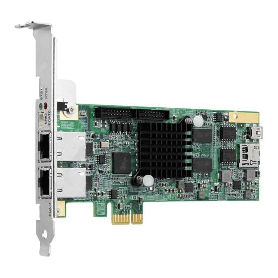
PCIe-833x Series 1.5 Exterior Profile All dimensions shown are in millimeters (mm) unless otherwise stated. NOTE: NOTE: 100.36 59.05 151.90 Figure 1-2: PCB Layout SW5 Card ID switch is located on the PCB rear side and is thus not shown in the Figure... -
Page 18: Table 1-1: Pcb Connector Legend
Leading EDGE COMPUTING Figure 1-3: PCB Connectors Location Connector Details 16-pin Box Header 8CH isolated digital I/O EMG (CN5) 2-pin Emergency stop signal input Basic EtherCAT ECAT0 RJ45 communication Advanced EtherCAT ECAT1 RJ45 communication (not DIP switch Card ID setup (0 to 15) shown) Table 1-1: PCB Connector Legend Introduction... -
Page 19: I/O Indicators
PCIe-833x Series 1.5.1 I/O Indicators Figure 1-4: I/O Indicators Indicator Color Function ™ STS1 Green Lit when SoftMotion initializes STS2 Lit when emergency occurs Table 1-2: I/O Indicator Legend 1.6 I/O Connectors 1.6.1 EtherCAT Connector ECAT0 & ECAT1 (reserved) Green... -
Page 20: Emg Connector
Leading EDGE COMPUTING Signal Table 1-3: EtherCAT Connector Pin Assignments Function Display Indication Unlit No Activity Yellow Activity Flashing Activity Unlit Green Link Table 1-4: EtherCAT Connector LED Legend 1.6.2 EMG Connector Name Function Common ground or power Emergency signal Table 1-5: EMG Connector Pin Assignments Introduction... -
Page 21: Di/O Connector
PCIe-833x Series 1.6.3 DI/O Connector CN8: General Digital Output and Digital Input (/Pulsar Input) Name Function E24V_ Isolation power Input, +24V EGND_ Ext. power ground Digital Input 0 Digital Input 1 PA_5V 5V Pulser A signal input PB_5V 5V Pulser B signal input... - Page 22 Leading EDGE COMPUTING This page intentionally left blank. Introduction...
-
Page 23: Getting Started
2.2 PCIe-833x Series Hardware Installation Hardware Configuration The PCIe-833x Series employs PCI Express Gen 2, the x1 Bus System BIOS can autoconfigure memory and IRQ channel. The terminal board DIN-37D provides connection to various sensors, actuators, and pulsar devices through the extension cable. -
Page 24: Troubleshooting
Leading EDGE COMPUTING that proper ESD (electrostatic discharge) protection measures are in place. 3. Connect the DIN-37D terminal board to the PCIe-833x Series (if applicable) with DSUB 37p cable. 4. Connect the EtherCAT type servo drive and I/O with Ethernet cables (CAT5e is recommended). 5. -
Page 25: Software Driver Installation
DIR) comply with that of the motor drive direction rather than two 2.3 Software Driver Installation 1. Download the PCIe-833x Series WDM file from ADLINK and run. Installation executes automatically. 2. Select Next as prompted to complete installation. Getting Started... - Page 26 Leading EDGE COMPUTING Getting Started...
- Page 27 PCIe-833x Series 3. After installation is complete, select Finish. 4. Ensure the Windows Device Manager lists the PCIe- 833x Series correctly. 5. Restart the computer now, or later, as desired. Getting Started...
-
Page 28: Sw5 Card Index Selection
Leading EDGE COMPUTING Please download the latest installation software from ADLINK's official website to maintain an optimum oper- ating environment. NOTE: NOTE: http://www.adlinktech.com/Motion-Control/index.php 2.4 SW5 Card Index Selection O N D I P Figure 2-1: SW5 Switch The SW5 switch is used to set the card index. For example, if the switch is set to 1-0-0-0 (ON-OFF-OFF-OFF), card ID is 1. -
Page 29: Ide 16P To Dsub 37P Bus
Table 2-1: SW5 Card Index 2.5 IDE 16p to DSUB 37p Bus An IDE cable connecting IDE 16-pin to DSUB 37-pin, it allows the PCIe-833x Series to support Px extension 4CH digital input and 4CH digital output. Figure 2-2: DSUB 37-pin Connector... -
Page 30: Signal Connection
EGND 2.6.2 General Digital Input & Pulsar Input The PCIe-833x Series provides 4 isolated digital input channels to connect 24VDC sensors, in which the first two channels are con- figured for pulsar input. An example signal wiring is shown. Getting Started... - Page 31 PCIe-833x Series 3.3V E24V 4.7k PS2805 FPGA DI0-1 Connection of a pulsar device with 5V power supply (if selected) is shown. The pulsar input frequency supports up to 1MHz in variant input modes that include CW/CCW mode and 1x/2x/4x AB phase modes.
-
Page 32: Emergency Stop Input (Emg)
Leading EDGE COMPUTING 2.6.3 Emergency Stop Input (EMG) The EMG signal identifies emergency stop input occurrence results in all motion functions forced to stop, while EtherCAT com- munication is retained for status monitoring. 3.3V 2.32k PS2805 FPGA 74LVC2G Getting Started... -
Page 33: Important Safety Instructions
PCIe-833x Series Important Safety Instructions For user safety, please read and follow all instructions, Warnings, Cautions, and Notes marked in this manual and on the associated device before handling/operating the device, to avoid injury or damage. S'il vous plaît prêter attention stricte à tous les avertissements et mises en garde figurant sur l'appareil , pour éviter des blessures... - Page 34 Leading EDGE COMPUTING Never attempt to repair the device, which should only be serviced by qualified technical personnel using suitable tools A Lithium-type battery may be provided for uninterrupted backup or emergency power. Risk of explosion if battery is replaced with one of an incorrect type;...
- Page 35 PCIe-833x Series BURN HAZARD Touching this surface could result in bodily injury. To reduce risk, allow the surface to cool before touching. RISQUE DE BRÛLURES Ne touchez pas cette surface, cela pourrait entraîner des blessures. Pour éviter tout danger, laissez la surface refroidir avant de la toucher.
- Page 36 Leading EDGE COMPUTING This page intentionally left blank. Important Safety Instructions...
-
Page 37: Getting Service
San Jose, CA 95138, USA Tel: +1-408-360-0200 Toll Free: +1-800-966-5200 (USA only) Fax: +1-408-360-0222 Email: info@adlinktech.com ADLINK Technology (China) Co., Ltd. 300 Fang Chun Rd., Zhangjiang Hi-Tech Park Pudong New Area, Shanghai, 201203 China Tel: +86-21-5132-8988 Fax: +86-21-5132-3588 Email: market@adlinktech.com...
Need help?
Do you have a question about the PCIe-833x Series and is the answer not in the manual?
Questions and answers