
Related Manuals for ADLINK Technology XMC-E540


Summary of Contents for ADLINK Technology XMC-E540
- Page 1 XMC-E540 Dual-port 10GBASE-T Ethernet XMC module with Intel® Ethernet Controller X540 User’s Manual Manual Rev.: 2.00 Revision Date: August 7, 2013 Part No: 50-1Z124-1000 Advance Technologies; Automate the World.
- Page 2 Revision History Revision Release Date Description of Change(s) 2.00 2013/08/07 Initial release Revision History...
-
Page 3: Preface
XMC-E540 Preface Copyright 2013 ADLINK Technology, Inc. This document contains proprietary information protected by copy- right. All rights are reserved. No part of this manual may be repro- duced by any mechanical, electronic, or other means in any form without prior written permission of the manufacturer. - Page 4 Using this Manual Audience and Scope The XMC-E540 User’s Manual is intended for hardware technicians and systems operators with knowledge of installing, configuring and operating industrial grade computer systems. Manual Organization This manual is organized as follows: Chapter 1, Introduction: Introduces the XMC-E540, its features, block diagrams, and package contents.
- Page 5 XMC-E540 Conventions Take note of the following conventions used throughout this manual to make sure that users perform certain tasks and instructions properly. Additional information, aids, and tips that help users perform tasks. NOTE: NOTE: Information to prevent minor physical injury, component dam- age, data loss, and/or program corruption when trying to com- plete a task.
- Page 6 This page intentionally left blank. Preface...
-
Page 7: Table Of Contents
Overview................1 Features................1 Block Diagram ..............2 Package Contents ............... 3 2 Specifications ..............5 XMC-E540 Module .............. 5 Intel® Ethernet Controller X540-AT2 ........6 Power Consumption ............7 3 Board Interfaces ..............9 XMC-E540 Board Layout............. 9 Connector Pin Assignments ..........10 4 Getting Started .............. - Page 8 This page intentionally left blank. viii...
-
Page 9: List Of Figures
XMC-E540 List of Figures Figure 1-1: XMC-E540 Functional Block Diagram ......2 Figure 3-1: XMC-E540 Board Layout..........9 List of Figures... - Page 10 This page intentionally left blank. List of Figures...
-
Page 11: List Of Tables
XMC-E540 List of Tables Table 2-1: XMC-E540 Power Consumption........7 Table 3-1: RJ-45 10GbE Connector Pin Definitions ....... 10 Table 3-2: XMC Connector Pin Definition ........11 List of Tables... - Page 12 This page intentionally left blank. List of Tables...
-
Page 13: Introduction
XMC-E540 Introduction 1.1 Overview The XMC-E540 is a dual-port 10GBASE-T Ethernet XMC module with equipped with an Inte® Ethernet Controller X540. Featured are dual RJ-45 copper ports supporting 10G/1000/100BASE-T with auto-negotiation, jumbo frames up to 15.5KB, TCP/UDP seg- mentation, IPv6 IP/TCP, IP/UDP receive checksum offload, FCoE Tx/Rx CRC offload, and 256KB FCoE transmit segmentation. -
Page 14: Block Diagram
1.3 Block Diagram MDI0 Intel X540 PCIe x1 / x2 / x4 / x8 MDI1 Figure 1-1: XMC-E540 Functional Block Diagram Introduction... -
Page 15: Package Contents
XMC-E540 1.4 Package Contents The XMC-E540 is packaged with the following components. If any of the items on the contents list are missing or damaged, retain the shipping carton and packing material and contact the dealer for inspection. Please obtain authorization before returning any prod- uct to ADLINK. - Page 16 This page intentionally left blank. Introduction...
-
Page 17: Specifications
XMC-E540 Specifications 2.1 XMC-E540 Module Standards VITA 42.3-2006 XMC PCI Express Protocol Layer Standard Form Factor • IEEE P1386, Standard XMC.3 • 74 mm x 149 mm x 8.2 mm (single width) Controller Intel® Ethernet Controller X540-AT2 • Dual port 100Mb/1000Mb/10Gb data rate •... -
Page 18: Intel® Ethernet Controller X540-At2
2.2 Intel® Ethernet Controller X540-AT2 The following section describes the features and functions of Intel® Ethernet Controller X540-AT2 10 GbE/1 GbE/100 Mb/s copper PHYs integrated on-chip Support for jumbo frames of up to 15.5 KB Flow control support: send/receive pause frames and receive FIFO thresholds Statistics for management and RMON... -
Page 19: Power Consumption
XMC-E540 2.3 Power Consumption The power consumption data of the XMC-E540 was measured installed in an ADLINK cPCI-6510 carrier blade using a Spirent SmartBits network performance analysis system. Power Consumption Engine Clock Current @ 5V Power (W) Idle Load 0.44 A 2.2 W... - Page 20 This page intentionally left blank. Specifications...
-
Page 21: Board Interfaces
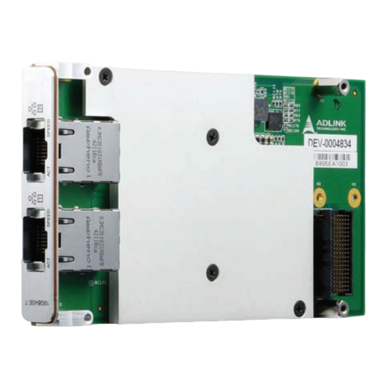
This chapter illustrates the board layout, connector pin assignments, and switch settings to familiarize users with the XMC-E540. 3.1 XMC-E540 Board Layout Intel X540 XMC connector CN2/3 RJ-45 10GbE connectors Figure 3-1: XMC-E540 Board Layout Figure 3-2: XMC-E540 Front Panel Board Interfaces... -
Page 22: Connector Pin Assignments
3.2 Connector Pin Assignments RJ-45 10G Ethernet Connectors (CN2/3) Pin # 100BASE-TX 10G/1000BASE-T LAN_TX0+ LAN_TX0- LAN_TX1+ LAN_TX2+ LAN_TX2- SPEED LAN_TX1- LAN_TX3+ LAN_TX3+ Table 3-1: RJ-45 10GbE Connector Pin Definitions Status SPEED Network link is not established or system powered off Link On (Green) 100 Mbps... - Page 23 XMC-E540 XMC Connector (CN1) Pin# PET0p0 PET0n0 3.3V PET0p1 PET0n1 VPWR Reserved MRSTI# PET0p2 PET0n2 3.3V PET0p3 PET0n3 VPWR Reserved Reserved PET0p4 PET0n4 3.3V PET0p5 PET0n5 VPWR Reserved PET0p6 PET0n6 3.3V PET0p7 PET0n7 VPWR VPWR Reserved PER0p0 PER0n0 Reserved PER0p1...
- Page 24 This page intentionally left blank. Board Interfaces...
-
Page 25: Getting Started
XMC-E540 Getting Started 4.1 Installing the Module 1. Remove the XMC slot filler faceplate from the front panel of the host board. 2. Insert the faceplate of the XMC module into the XMC slot in the front panel of the host board. -
Page 26: Driver Installation
4.2 Driver Installation The XMC-E540 drivers can be found on the ADLINK All-In-One DVD at X:\XMC\XMC-E540\LAN, or at the ADLINK website (http:/ /www.adlinktech.com). Driver installation procedures for Win- dows 7 are described below. 1. Install the Windows operating system before installing any driver. -
Page 27: Important Safety Instructions
XMC-E540 Important Safety Instructions For user safety, please read and follow all instructions, WARNINGS, CAUTIONS, and NOTES marked in this manual and on the associated equipment before handling/operating the equipment. Read these safety instructions carefully. Keep this user’s manual for future reference. - Page 28 Never attempt to fix the equipment. Equipment should only be serviced by qualified personnel. A Lithium-type battery may be provided for uninterrupted, backup or emergency power. Risk of explosion if battery is replaced with one of an incorrect type. Dispose of used batteries appropriately. WARNING: Equipment must be serviced by authorized technicians when:...
-
Page 29: Getting Service
5215 Hellyer Avenue, #110, San Jose, CA 95138, USA Tel: +1-408-360-0200 Toll Free: +1-800-966-5200 (USA only) Fax: +1-408-360-0222 Email: info@adlinktech.com ADLINK Technology (China) Co., Ltd. Address: (201203) 300 Fang Chun Rd., Zhangjiang Hi-Tech Park, Pudong New Area, Shanghai, 201203 China Tel: +86-21-5132-8988 Fax:... - Page 30 84 Genting Lane #07-02A, Cityneon Design Centre, Singapore 349584 Tel: +65-6844-2261 Fax: +65-6844-2263 Email: singapore@adlinktech.com ADLINK Technology Singapore Pte. Ltd. (Indian Liaison Office) Address: 1st Floor, #50-56 (Between 16th/17th Cross) Margosa Plaza, Margosa Main Road, Malleswaram, Bangalore-560055, India Tel: +91-80-65605817, +91-80-42246107 Fax: +91-80-23464606 Email: india@adlinktech.com...
Need help?
Do you have a question about the XMC-E540 and is the answer not in the manual?
Questions and answers