
Related Manuals for ADLINK Technology EMX-100


Summary of Contents for ADLINK Technology EMX-100
- Page 1 EMX-100 4-axis Ethernet-based Motion Controller User’s Manual Manual Rev.: Revision Date: Apr. 17, 2019 Part No: 50-1Z257-1010 Leading EDGE COMPUTING...
- Page 2 Leading EDGE COMPUTING Revision History Revision Release Date Description of Change(s) Apr. 17, 2019 Initial Release...
- Page 3 EMX-100 Preface Copyright 2019 ADLINK Technology Inc. This document contains proprietary information protected by copy- right. All rights are reserved. No part of this manual may be repro- duced by any mechanical, electronic, or other means in any form without prior written permission of the manufacturer.
- Page 4 Leading EDGE COMPUTING Battery Labels (for products with battery) California Proposition 65 Warning WARNING: This product can expose you to chemicals including acrylamide, arsenic, benzene, cadmium, Tris(1,3-dichloro-2-propyl) phosphate (TDCPP), 1,4- Dioxane, formaldehyde, lead, DEHP, styrene, DINP, BBP, PVC, and vinyl materials, which are known to the State of California to cause cancer, and acrylamide, benzene, cadmium, lead, mercury, phthalates, toluene, DEHP, DIDP, DnHP, DBP, BBP, PVC, and vinyl materials, which are known to the State of California to cause...
- Page 5 EMX-100 Information to prevent minor physical injury, component dam- age, data loss, and/or program corruption when trying to com- plete a task. CAUTION: Information to prevent serious physical injury, component damage, data loss, and/or program corruption when trying to complete a specific task.
- Page 6 Leading EDGE COMPUTING This page intentionally left blank. Preface...
-
Page 7: Table Of Contents
EMX-100 Table of Contents Preface ..................iii List of Figures ................ ix 1 Introduction ................ 1 Features................2 Specifications............... 3 Software Support ..............5 OS/Programming Library ..........5 MotionCreatorPro 2 ............5 Mechanical Drawings............6 Power Connectors ............... 8 Motor Drive Connector CM1 to CM4 ........9 Dedicated Motion I/O Connector ........ - Page 8 Hardware Installation ............27 Software Installation............27 A Appendix: Controller IP Settings........29 Connection Example: Two EMX-100 units connected to a single Ethernet port... 29 A.1.1 Check/set the PC Network Interface......29 A.1.2 Open Set IP Tool and Select Initial......32 Connection Example: One EMX-100 connected to each of two Ethernet ports..
-
Page 9: List Of Figures
EMX-100 List of Figures Figure 1-1: Front View ..............6 Figure 1-2: (Left) Side View ............7 Figure 1-3: Top View (incl. RJ-45 connector and device Reset button)..8 Figure 1-4: Underside View ............8 List of Figures... - Page 10 Leading EDGE COMPUTING This page intentionally left blank. List of Figures...
-
Page 11: Introduction
MotionCreatorPro 2™, supporting all motion control libraries. For users who are already familiar with ADLINK's motion control products, there is no need to relearn, because the EMX-100 has a consistent programming approach. For users new to ADLINK's motion control products, the learning curve is significantly short- ened, thanks to the intuitive nature of the APS library. -
Page 12: Features
Leading EDGE COMPUTING 1.1 Features Libraries and utilities for Windows 7/10 Expansion deployment up to 100 meters via Ethernet Support for standard C++, C#, VB.NET 2-axis position Compare and Trigger output Includes MotionCreator Pro 2 Windows-based application development software ... -
Page 13: Specifications
EMX-100 1.2 Specifications General Specifications Dimensions 215 (l) x 164 (w) x 39 (h) mm Weight 1030kg ±10g Installation method 4 x screw lock Power module input voltage 24 VDC ±10% Power consumption 11.48W Overvoltage protection ≥ 28V ≥ 1.25A... - Page 14 Leading EDGE COMPUTING Controller pulse output Differential OUT/DIR, CW/CCW and 2x, 4x format AB phase Encoder pulse input Differential CW/CCW and 1x, 2x, 4x AB format phase Max. encoder input 4Mhz (under 4 x AB phase) frequency Motion Control Function Motion track T/S curve Point-to-point...
-
Page 15: Software Support
2ms, feedback function less than 1ms, state update is 2ms 1.3 Software Support OS/Programming Library The EMX-100 supports Windows 7/10 64/32-bit OS and provides DLL files for easy application development by users. MotionCreatorPro 2 MotionCreatorPro 2™ is a user interface exclusively developed for ADLINK motion control products in a standard Windows environ- ment. -
Page 16: Mechanical Drawings
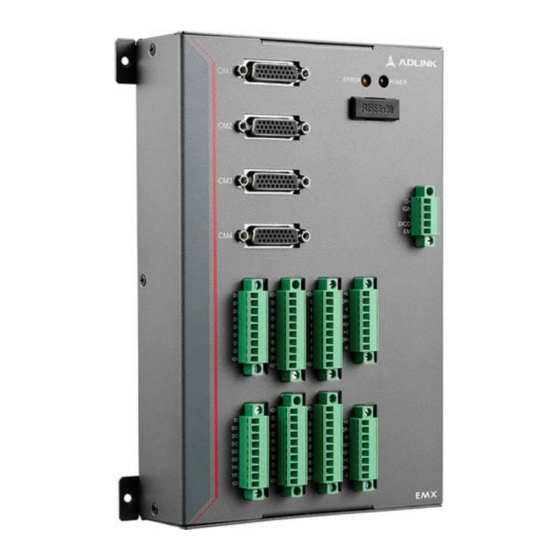
Leading EDGE COMPUTING 1.4 Mechanical Drawings All dimensions shown are in millimeters (mm) unless otherwise stated. NOTE: NOTE: ERROR POWER I24V IGND DICOM IGND IGND +EL1 DI17 ORG1 DI18 -EL1 DI19 IGND DI20 IGND DI21 +EL2 DI22 ORG2 DI23 -EL2 IGND DI24 IGND... -
Page 17: Left) Side View
EMX-100 Figure 1-2: (Left) Side View Barcode label MAC address label Introduction... -
Page 18: Power Connectors
Leading EDGE COMPUTING RESET ETHERNET Figure 1-3: Top View (incl. RJ-45 connector and device Reset button) Figure 1-4: Underside View 1.5 Power Connectors The main power supply connectors from which the external supply controller 24VDC power is supplied. In addition to the power input, the DICOM contact provides a choice of digital input point types, such as Source or Sink. -
Page 19: Motor Drive Connector Cm1 To Cm4
EMX-100 1.6 Motor Drive Connector CM1 to CM4 A D-SUB connector for the motor driver. The EMX-100 provides a series of cables of different lengths that can interface with com- monly used servo drives. Generally, the servo driver terminal is the popular SCSI-50pin connecter. -
Page 20: Dedicated Motion I/O Connector
Leading EDGE COMPUTING Pin Name Function Name Function Encoder A- Isolation IGND phase(+) Ground Direction Alarm reset DIR- signal(-) Direction Servo alarm DIR+ signal(+) I/O power supply Encoder Z- I24V +24V phase(-) Encoder Z- IGND Isolation ground phase(+) 1.7 Dedicated Motion I/O Connector A quick-release Phoenix connector for the origin switch and limit switch on the motion control platform. -
Page 21: General Input Connector
EMX-100 Pin Name Function Name Function Axis 3 Negative Axis 4 Origin -EL3 ORG4 Limit Switch Switch Axis 4 Negative IGND Isolation Ground 8 -EL4 Limit Switch 1.8 General Input Connector Another quick-release Phoenix connector for use with digital input points on the equipment platform, generally connecting sensors such as proximity or photoelectric switches. -
Page 22: General Digital Output Connector
Leading EDGE COMPUTING Pin Name Function Name Function Isolation DI12 Digital input IGND Ground Pin Name Function Name Function IGND Isolation Ground 6 DI21 Digital input DI17 Digital input DI22 Digital input DI18 Digital input DI23 Digital input DI19 Digital input DI24 Digital input Isolation... -
Page 23: Reset Button
EMX-100 Pin Name Function Name Function Digital Output DO14 Digital Output Axis 1 compare DO10 Digital Output TRG1 trigger output Axis 2 compare DO11 Digital Output TRG2 trigger output Isolation DO12 Digital Output IGND Ground DO13 Digital Output Pin Name... -
Page 24: Status Leds
Leading EDGE COMPUTING Since the EMX-100 will restart during the reset process, close the application software on the PC side, or unplug the network cable, and wait until the Error indicator lights before resetting. Once the Error indicator is lit: 1. -
Page 25: Pulse Output I/F Circuit
EMX-100 Motion Controller Fuse I24V +VOUT +VIN Isolation 5.6 kΩ/0.25W DC/DC -VIN -VOUT IGND 1.13 Pulse Output I/F Circuit The following figure shows the internal circuit of the pulse wave output interface, a differential output mode that can resist common mode noise (Single-ended mode is not supported). -
Page 26: Digital Input I/F Circuit
Leading EDGE COMPUTING Motor Driver Motion Controller 2.2 k 2.2 k 2.2 k 2.2 k 2.2 k 2.2 k SGND SGND 1.15 Digital Input I/F Circuit As shown, the internal circuit of the digital input interface can be selected by grounding DICOM or connecting 24VDC. If grounded, the external device to be docked is Sink. -
Page 27: Digital Output I/F Circuit
EMX-100 SOURCE SINK Motion Controller Motion Controller I24 V I24 V IGND 24 V 24 V IGND 3.3 V 3.3 V DICOM indicators DICOM indicators #DI1 #DI1 4.7 k DI-1 4.7 k DI-1 #DI2 #DI2 4.7 k DI-2 4.7 k... - Page 28 DO-1 #DO1 DO-2 #DO2 IGND The following shows connection of the motor drive. For example, because the interface on EMX-100 is sink type, the servo drive side must be source type. Motion Controller 24 V indicators 3.6 k 3.6 k...
-
Page 29: Position Comparison And Trigger Output I/F Circuit
EMX-100 1.17 Position Comparison and Trigger Output I/F Circuit The internal circuit of the trigger output and the digital output inter- face is generally used where the control process needs to be accurately matched with the motor position, for example, trigger- ing an industrial camera image capture. -
Page 30: Power Input And Grounding I/F Circuit
Leading EDGE COMPUTING control motors and sends an emergency stop signal to the motor drive end, because this signal is interlocked with the EMG on the motor connector CM1 to CM4. When the emergency stop input signal of the controller is valid, the controller sends an emergency stop signal to the servo motor via the direct circuit. -
Page 31: Home Return Mode
Note: RJ45 Conn. chassis conect to Earth ground. 1.20 Home Return Mode EMX-100 provides three homing modes, each executed automati- cally with no need for additional process controls. Each mode can run with the Z-phase (EZ) search function, generally enabled when using servo motor, and disabled when using stepper motor. -
Page 32: Mode 1: Using Org & El
Leading EDGE COMPUTING Mode 1: Using ORG & EL Velocity Case1: Posi on Mee ng ORG before EL Case2: Posi on Mee ng ORG a er EL * Home return process: Go forward to EL direction --> through ORG --> meeting EL and decelerate to stop -->... -
Page 33: Mode 2: Using Org Or El Only
EMX-100 Mode 2: Using ORG or EL only Velocity Case1: Decelerate within ORG area Case2: Decelerate over ORG area Case3: Turn back to search for ORG Velocity Case1: Posi on Decelerate within EL area Case2: Posi on Decelerate over EL area... - Page 34 Leading EDGE COMPUTING * Home return process: Go forward to ORG/EL direction --> meeting ORG/EL and decelerate to stop --> reverse with low speed to search for ORG/EL --> Find ORG/EL and decelerate to stop * Use ORG or EL (EZ enable) Velocity Case1: Posi on...
-
Page 35: Mode 3: Using Org Or El Only
EMX-100 Velocity Case1: Posi on Decelerate within EL area Case2: Posi on Decelerate over EL area Mode 3: Using ORG or EL only Velocity ORG or EL Home Search Target = ORG Posi on Velocity Home Search Target Posi on... - Page 36 Leading EDGE COMPUTING * Home return process: Go forward to ORG/EL direction --> meeting ORG/EL and decelerate to stop * Use ORG or EL (EZ enable) Velocity ORG or EL Posi on Velocity Posi on Posi on Introduction...
-
Page 37: Getting Started
Save the shipping materials and carton to ship or store the product in the future. 2.2 Hardware Installation Install the EMX-100 on the distribution box via the four corner screw holes. Connect through isolated on-site internet, rated at or above CAT5e. - Page 38 Leading EDGE COMPUTING This page intentionally left blank. Getting Started...
-
Page 39: A Appendix: Controller Ip Settings
EMX-100 Appendix A: Controller IP Settings A.1 Connection Example: Two EMX-100 units connected to a single Ethernet port Up to four sets can be connected, this example connects two CAT5e Cable EMX-100 #1 PC with Switch/Hub Ethernet port CAT5e Cable... - Page 40 Leading EDGE COMPUTING 3. Select Internet Protocol Version 4 (TCP/IP V4) in the content window and select content. Controller IP Settings...
- Page 41 EMX-100 4. Cancel the Automatic IP setting and use the displayed IP address (limited to 5 to 253, the gateway is fixed to 254) Controller IP Settings...
-
Page 42: Open Set Ip Tool And Select Initial
Leading EDGE COMPUTING A.1.2 Open Set IP Tool and Select Initial The system will prompt to perform Reset after clicking initial but- ton, resetting IP to default address 192.168.0.1 for first connec- tion. If it has been reset or confirmed as the default IP, ignore the message. - Page 43 EMX-100 1. Since the IP of each EMX-100 is the same at the begin- ning (after reset), connect one device at a time to change IP. 2. Connect the first device and select Device 0, enter the IP (default value is 192.168.0.1), and select set device 0.
-
Page 44: Connection Example: One Emx-100 Connected To Each Of Two Ethernet Ports
Leading EDGE COMPUTING 5. After setting the IP for both EMX-100 units, connect both to the network cable and select confirm your setting to modify the system INI configuration file. During the pro- cess, the Error light will extinguish. The OK dialog box appears indicating setting is complete. - Page 45 192.168.0.5 and the other at 192.168.5.200. 1. Using the Set IP Tool, as in Example 1, select device 0 to complete the first network port and the first EMX-100 settings. Once setting is complete, remove the EMX-100 from the first network port.
- Page 46 Leading EDGE COMPUTING 3. Select device1 to set IP 192.168.5.1, select set device1. After about 14 seconds, the Error indicator lights and setting is complete. Controller IP Settings...
- Page 47 EMX-100 Since the IP address of the second network port is 192.168.0.200, this network segment is different from device1. The next operation of the Setup IP tool must not find device 1, so returning to the sec- ond network port must be done manually.
-
Page 48: Troubleshooting
Leading EDGE COMPUTING 5. After the second network port is set, connect the first EMX-100 to the first network port. At this time, the sec- ond EMX-100 is also connected to the second network port. Confirm your setting. After OK, select check con- nection again, and setting is complete. -
Page 49: Updating Firmware
EMX-100 A.4 Updating Firmware 1. Execute sw_update.exe (the Error indicator lights) 2. Select Update Firmware. The Error light extinguishes twice for about 2 seconds, and the Please Wait message appears 3. After holding confirming for about 5 seconds, the Error indicator lights and Updating message appears. - Page 50 Leading EDGE COMPUTING 4. After about 16 seconds, the Error indicator lights again to indicate that update is complete. Select OK to finish. (If you do not press OK in time, an Error is reported, select OK to re-light) 5. Select Get Version and the Version display appears. FAMC SW Ver is this version.
-
Page 51: Important Safety Instructions
EMX-100 Important Safety Instructions For user safety, please read and follow all instructions, Warnings, Cautions, and Notes marked in this manual and on the associated device before handling/operating the device, to avoid injury or damage. S'il vous plaît prêter attention stricte à tous les avertissements et mises en garde figurant sur l'appareil , pour éviter des blessures... - Page 52 Leading EDGE COMPUTING Never attempt to repair the device, which should only be serviced by qualified technical personnel using suitable tools A Lithium-type battery may be provided for uninterrupted backup or emergency power. Risk of explosion if battery is replaced with one of an incorrect type;...
- Page 53 EMX-100 BURN HAZARD Touching this surface could result in bodily injury. To reduce risk, allow the surface to cool before touching. RISQUE DE BRÛLURES Ne touchez pas cette surface, cela pourrait entraîner des blessures. Pour éviter tout danger, laissez la surface refroidir avant de la toucher.
- Page 54 Leading EDGE COMPUTING This page intentionally left blank. Important Safety Instructions...
-
Page 55: Getting Service
San Jose, CA 95138, USA Tel: +1-408-360-0200 Toll Free: +1-800-966-5200 (USA only) Fax: +1-408-360-0222 Email: info@adlinktech.com ADLINK Technology (China) Co., Ltd. 300 Fang Chun Rd., Zhangjiang Hi-Tech Park Pudong New Area, Shanghai, 201203 China Tel: +86-21-5132-8988 Fax: +86-21-5132-3588 Email: market@adlinktech.com...
Need help?
Do you have a question about the EMX-100 and is the answer not in the manual?
Questions and answers