
Related Manuals for ADLINK Technology PCIe-7856


Summary of Contents for ADLINK Technology PCIe-7856
- Page 1 PCIe-7856/7853 Master-Slave Distributed Motion and I/O Master Controller User’s Manual Manual Rev.: Sept. 17, 2020 Revision Date: 50-15113-1010 Part No: Leading EDGE COMPUTING...
- Page 2 Leading EDGE COMPUTING Revision History Revision Release Date Description of Change(s) 2020-02-27 Initial release Add PCIe-7853; integrate HSL System 2020-09-17 documentation Revision History...
- Page 3 PCIe-7856/7853 Preface Copyright © 2020 ADLINK Technology Inc. This document contains proprietary information protected by copy- right. All rights are reserved. No part of this manual may be repro- duced by any mechanical, electronic, or other means in any form without prior written permission of the manufacturer.
- Page 4 Leading EDGE COMPUTING California Proposition 65 Warning WARNING: This product can expose you to chemicals including acrylamide, arsenic, benzene, cadmium, Tris(1,3-dichloro-2-propyl)phosphate (TDCPP), 1,4-Diox- ane, formaldehyde, lead, DEHP, styrene, DINP, BBP, PVC, and vinyl materials, which are known to the State of California to cause cancer, and acrylamide, benzene, cadmium, lead, mercury, phthalates, toluene, DEHP, DIDP, DnHP, DBP, BBP, PVC, and vinyl materials, which are known to the State of California to cause...
-
Page 5: Table Of Contents
List of Tables................xi 1 Introduction ................ 1 Specifications............... 3 Supported Software ............. 4 2 Installation ................5 Package Contents ............... 5 PCIe-7856 Mechanical Drawing .......... 6 Driver Installation ..............7 2.3.1 PCIe-7856 ..............7 2.3.2 PCIe-7853 ..............7 Troubleshooting ..............7 Signal Connections.............. - Page 6 Leading EDGE COMPUTING HSL Slave I/O Modules............24 4.1.1 Discrete I/O Module ..........24 4.1.2 Analog I/O Modules ..........25 General Specifications ............26 4.2.1 Digital I/O Modules ........... 26 4.2.2 Analog I/O Modules ..........27 4.2.3 HSL Module DIP Switch ........... 28 4.2.4 Daughter Board/Module Dimensions......
- Page 7 PCIe-7856/7853 Discrete I/O................ 87 Analog I/O................96 9 How to Program with HSL Function Library....103 Programming with HSL DLL ..........103 Important Safety Instructions ..........107 Getting Service..............109...
- Page 8 Leading EDGE COMPUTING This page intentionally left blank. viii...
-
Page 9: List Of Figures
Figure 1-1: PCIe-7856 Block Diagram ..........2 Figure 2-1: PCIe-7856 Mechanical Drawing ........6 Figure 2-2: LED Indicators on the PCIe-7856 ........10 Figure 3-1: MNET Distributed Motion Control System ..... 13 Figure 3-2: MNET System Communication Sequence ....17 Figure 3-3: MNET-MIA with MINAS A4 Servo Driver....... - Page 10 Leading EDGE COMPUTING This page intentionally left blank. List of Figures...
-
Page 11: List Of Tables
PCIe-7856/7853 List of Tables Table 3-1: MNET System Specifications ........14 Table 3-2: MNET Motion Module Series......... 18 Table 4-1: HSL Discrete I/O Module Series........24 Table 4-2: HSL Discrete I/O Module Selection Guide..... 24 Table 4-3: HSL Analog I/O Module Series........25 Table 4-4: HSL Analog I/O Module Selection Guide....... - Page 12 Leading EDGE COMPUTING This page intentionally left blank. List of Tables...
-
Page 13: Introduction
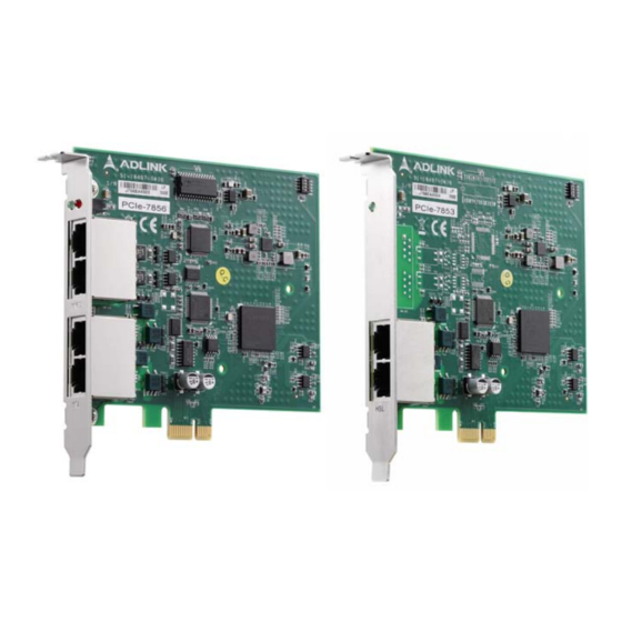
256 axes plus minimal command execution time for single-axis control. The PCIe-7856 is a PCI Express interface card with two ports for MNET and HSL systems for distributed motion and I/O modules for a wide variety of machine automation applications. -
Page 14: Figure 1-1: Pcie-7856 Block Diagram
Fast, time-deterministic scanning with hundreds of discrete I/O points (up to 2,016 points). Rapid, real-time scanning to support high-speed and high- response motion control of up to 256 axes. The PCIe-7856 block diagram is as follows. Figure 1-1: PCIe-7856 Block Diagram Introduction... -
Page 15: Specifications
PCIe-7856/7853 1.1 Specifications PCIe-7856 PCIe-7853 PCI Express x1, Plug and Play Dedicated Motion Controller Motionnet ASIC master control Master Controller (80 MHz external clock) Dedicated I/O Controller: HSL ASIC master control (48 MHz external Clock) RS-485 with transformer isolation Half duplex communication Motion 2.5/5/10/20 Mbps transmission... -
Page 16: Supported Software
Leading EDGE COMPUTING 1.2 Supported Software Program Library ADLINK provides Windows WDM drivers and DLL function librar- ies for the PCIe-7856. These function libraries are shipped with the board and they support Windows 7/8/10 (32/64-bit). Introduction... -
Page 17: Installation
PCIe-7856/7853 Installation This chapter describes how to install and set up the PCIe-7856. Please follow these steps: Check the product for any sign of defect or damage (use Figure 2-1 on page 6 as a reference). Install software drivers (Section 2.3, page 7). -
Page 18: Pcie-7856 Mechanical Drawing
Leading EDGE COMPUTING 2.2 PCIe-7856 Mechanical Drawing Dimensions: mm 121.81 119.91 LEDGR1 MRJ45 HRJ45 Figure 2-1: PCIe-7856 Mechanical Drawing MRJ45: MNET connection port HRJ45: HSL connection port SW1: Card identification switch LEDGR1: HSL/Motionnet Scan LEDs Installation... -
Page 19: Driver Installation
PCIe-7856/7853 2.3 Driver Installation 2.3.1 PCIe-7856 Open a web browser and navigate to the PCIe-7856/7853 product web page (https://www.adlinktech.com/Products/Motion_Control/ DistributedMotionControl/PCIe-7856_7853). Under Technical Resources, select Driver to see the list of available drivers. After downloading the required ZIP file, extract and double-click the enclosed executable file to run the installer. -
Page 20: Connecting Hsl/Mnet Slave Modules
Leading EDGE COMPUTING 2.5.1 Connecting HSL/MNET Slave Modules Wiring for MNET Motion Slave Modules MNET Slave Modules MRJ45 Ethernet Cable Wiring for HSL I/O Slave Modules HSL Slave Modules HSL Slave Modules HRJ45 HRJ45 Ethernet Cable Ethernet Cable Ethernet Cable (CAT5e Recommended) Installation... -
Page 21: Rj45 Pin Assignments
The master sends commands to slave motion controllers and obtains motion status from them. The PCIe-7856 provides two MNET master connection ports for greater wiring flexibility. The pin assignments of the MRJ45 connector on the PCIe-7856 are as listed below: Pin No. -
Page 22: Hsl And Motionnet Led Indicators
LEDs will be off. After initialization, the LEDs will begin blink- ing at a 1 Hz frequency. When the PCIe-7856 connects to an HSL slave module, the green LED will turn on and remain constantly on during the scanning pro- cess, after which the green LED will continue blinking at 1 Hz. -
Page 23: Sw1 Card Id Switch Settings
PCIe-7856/7853 2.6 SW1 Card ID Switch Settings The card ID can be set via the SW1 DIP switch as follows. ON = 1 0000 Card ID 0 0001 Card ID 1 0010 Card ID 2 … … 1110 Card ID 14... - Page 24 Leading EDGE COMPUTING This page intentionally left blank. Installation...
-
Page 25: Mnet Master-Slave Motion System
Nippon Pulse Motor (NPM). It features strong performance with a maximum transfer speed of up to 20Mbps. The PCIe-7856 is equipped with one MNET port offering control of up to 256 axes via serial connections. ADLINK MNET solutions... -
Page 26: Mnet System Specifications
Leading EDGE COMPUTING 3.1 MNET System Specifications The two major functions of a Motionnet (MNET) system are serial communication and motion control. Item Specifications Maximum of 100m (at a data transfer speed of 20 Mbps with 32 devices connected) Total serial communi- cation line length Maximum of 50m (at a data transfer speed of... -
Page 27: Wiring Cables
PCIe-7856/7853 3.1.1 Wiring Cables The PCIe-7856 system guarantees enhanced quality for high- speed communication and is designed to be connected with user- provided LAN cables suitable for 100BASE-T and 1000BASE-T. Because these cables have well-known specifications and are cheap and easy to obtain, we do not provide them and do not include them in our product lines. -
Page 28: Mnet System Communication
Leading EDGE COMPUTING 3.1.2 MNET System Communication The following is a communication block diagram for a Missionnet (MNET) system. Motionnet Motion MNET Single Host modules Amp. Command Command Delivering Command Dispatching Command Executing Launching Command Launching Within the MNET system, remote modules communicate with each other using MNET network packets, but users do not need to understand the contents of these packets. -
Page 29: Figure 3-2: Mnet System Communication Sequence
However, in a direct data communication the communication time will vary based on how the communication is controlled by the user’s program and the time needed to access the PCIe-7856. Cyclic communication Send... -
Page 30: Mnet Motion Modules
Leading EDGE COMPUTING 3.2 MNET Motion Modules Motionnet (MNET) motion slave modules are wire-saving solu- tions. ADLINK provides two types of general purpose 4-axis mod- ules: MNET-4XMO and MNET-4XMO-C. Both offer crucial motion functions such as point-to-point, zero-position searching, program- mable acceleration/deceleration, T/S curve speed profile, etc. - Page 31 PCIe-7856/7853 ear acceleration/deceleration, S-curve acceleration/deceleration, preset positioning, and zero return) using serial communications. Since these modules can connect directly to the mechanical I/O signals of a servo driver, they do not need the special servo driver cable required of conventional motion control modules, thus sav-...
-
Page 32: Motion Module Mechanical Drawings
Leading EDGE COMPUTING 3.2.1 Motion Module Mechanical Drawings units: mm Figure 3-3: MNET-MIA with MINAS A4 Servo Driver MNET Master-Slave Motion System... -
Page 33: Figure 3-4: Mnet-4Xmo-(C) Mechanical Diagram
PCIe-7856/7853 units: mm Figure 3-4: MNET-4XMO-(C) Mechanical Diagram MNET Master-Slave Motion System... - Page 34 Leading EDGE COMPUTING This page intentionally left blank. MNET Master-Slave Motion System...
-
Page 35: Hsl Slave Modules
PCIe-7856/7853 HSL Slave Modules High Speed Link (HSL) is a master-slave network system featuring an innovative distributed architecture that modularizes communi- cation, I/O functionality, and signal termination. ADLINK provides slave I/O modules and terminal bases to meet your particular application requirements, including discrete I/O, analog I/O, and motion control. -
Page 36: Hsl Slave I/O Modules
Leading EDGE COMPUTING 4.1 HSL Slave I/O Modules 4.1.1 Discrete I/O Module ADLINK provides a discrete M series daughter board form factor I/O module with aluminum cover. Series Model Discrete Discrete Relay Slave Index Inputs Outputs Outputs Occupation HSL-DI32-M-N 2 (consecutive from odd number) HSL-DO32-M-N 2 (consecutive from... -
Page 37: Analog I/O Modules
PCIe-7856/7853 4.1.2 Analog I/O Modules ADLINK provides M and U analog I/O modules, as shown below. Series Model Analog Input Analog Output Slave Index Occupation HSL-AI16AO2-M-VV 2 (leap number) HSL-AO4 Table 4-3: HSL Analog I/O Module Series The selection guide is as follows. -
Page 38: General Specifications
Leading EDGE COMPUTING 4.2 General Specifications 4.2.1 Digital I/O Modules Photo Couple Isolation 2500 VRMS Discrete Input Input Impedance 4.7 kΩ Input Voltage +24 V Input Current -10 mA For NPN +10 mA For PNP Operation Voltage (@ ON: 11.4 V (max.) For NPN 24 V... -
Page 39: Analog I/O Modules
PCIe-7856/7853 4.2.2 Analog I/O Modules A/D Resolution 16-bit (14-bit guaranteed) Analog Input Input Range For VV type: ±10 V, ±5, ±2.5, ±1.25 V For AV type: 20 mA, 10 mA, 5 mA A/D Conversion 10 μs Signal Type 16-ch Single Ended; 8-ch Differential... -
Page 40: Hsl Module Dip Switch
Leading EDGE COMPUTING 4.2.3 HSL Module DIP Switch Figure 4-1: HSL Module DIP Switch Location ON = 1 100000 address 1 010000 address 2 … … 011111 address 62 111111 address 63 OFF = 0 1. The address (or index) ‘0’ is reserved for the master. 2. -
Page 41: Daughter Board/Module Dimensions
PCIe-7856/7853 4.2.4 Daughter Board/Module Dimensions units: mm HSL Slave Modules... - Page 42 Leading EDGE COMPUTING M: Daughter board with aluminum cover (125 mm × 80 mm) units: mm HSL Slave Modules...
- Page 43 PCIe-7856/7853 U: Low-profile I/O module (71.8 mm × 138 mm) units: mm HSL Slave Modules...
-
Page 44: Wiring Diagrams
Leading EDGE COMPUTING 4.2.5 Wiring Diagrams R (Relay Output): Load NO.n Internal Circuit COM.n Analog Input (Differential Voltage Input): Differential Signal Source IN(+) IN(-) <30V AGND Analog Input (Single-Ended Voltage Input): Ground Signal Source IN(+) AGND HSL Slave Modules... - Page 45 PCIe-7856/7853 Analog Input (Current Measure): Current Source IN(+) IN(-) R=125 Ohm %1 accuracy N (NPN Sinking-type Sensor Input): Internal Circuits Circuit N (Dry Contact Input): Internal Circuits HSL Slave Modules...
- Page 46 Leading EDGE COMPUTING P (PNP Sourcing-type Sensor Input): Circuit Internal Circuits P (Wet Contact Input): Internal Circuits HSL Slave Modules...
- Page 47 PCIe-7856/7853 N (NPN Sinking Output): P (PNP Sourcing Output): HSL Slave Modules...
-
Page 48: Terminal Base Motion Control Modules
Leading EDGE COMPUTING 4.2.6 Terminal Base Motion Control Modules The terminal bases (TBs) include: HSL-TB32-U-DIN HSL-TB64-DIN HSL-TB32-M-DIN HSL-TB32-MD Features Field I/O wiring connection for HSL I/O modules Screw or spring terminal for easy field wiring ... - Page 49 PCIe-7856/7853 Jumper Settings Since HSL is a serial transmission system, a terminator should be set at the end of the cable. Each TB has a jumper-selectable ter- minator on board. Only the last module needs to have the termina- tor enabled.
- Page 50 Leading EDGE COMPUTING HSL-TB32-MD Jumper Settings HSL Slave Modules...
- Page 51 PCIe-7856/7853 Dimensions DB with HSL-TB32-U-DIN (126 × 120.1 × 107.3) mm units: mm HSL Slave Modules...
- Page 52 Leading EDGE COMPUTING DB with HSL-TB64-DIN (168.7 × 120.1 × 107.3) mm units: mm HSL Slave Modules...
- Page 53 PCIe-7856/7853 M module with HSL-TB32-M-DIN (128.5 × 85.5 × 108) mm units: mm HSL Slave Modules...
- Page 54 Leading EDGE COMPUTING HSL-TB32-MD (129 × 107) mm units: mm HSL Slave Modules...
-
Page 55: Managing Slave Indexes In An Hsl Network
1 and 3. You must assign a value of 4 to the parameter “MOD_No” “APS_set_field_bus_slave_param()” ensure correct communication (PCIe-7856 only). Examples The following examples are provided for user reference. All the modules involved are assumed to be in full-duplex mode. - Page 56 Leading EDGE COMPUTING Example 1 HSL-DI16DO16-UD×2, HSL-DI32-MN×2, and HSL-AI16AO2- VV×1 are installed (with all slave modules in full-duplex mode) under two different conditions: Condition 1: HSL-AI16AO2-VV operating at 6 Mbps. ADLINK suggests the following slave index configuration: Item DIP Switch Index Occupation in HSL HSL-DI32-M-N #1 1, 2 HSL-DI32-M-N #2...
- Page 57 PCIe-7856/7853 6 Mbps HSL-D16DO2-UL ×2, HSL-DI32-UD x 2 HSL-AI16AO2-M-VV 12 Mbps Consequently, the cycle time of the first master controller is 30.33 µs × 6 and the cycle time of the second master controller is 45.5 µs at 12 Mbps, full-duplex mode.
- Page 58 Leading EDGE COMPUTING The scan time required is 30.33 µs × 7. These modules may be connected with one master controller. The HSL-AI16AO2-M-VV module will connect to another master controller. The manage- ment table and illustration below are provided for reference. Group 2 DIP Switch Index Occupation in HSL HSL-AI16AO2-M-VV...
-
Page 59: Motioncreatorpro 2 (Mcp2)
PCIe-7856 to verify correct operation. The MCP2 software provides a simple yet powerful means to set up, config- ure, test, and debug a motion control system that uses PCIe-7856. 5.1 About MCP2 Before running MCP2, please note the following. -
Page 60: Mcp2 Features
Leading EDGE COMPUTING 5.3 MCP2 Features 5.3.1 Main Menu Launching MCP2.exe will present the user with the main menu. Refer to the following images and descriptions for details on all the available features. To exit the program at any time, select “Exit” from the “File”... - Page 61 PCIe-7856/7853 Movement Button Function Description Single Movement Single-axis movement (PTP), including absolute and relative functions. Home Return Movement Home return movement. Interpolation Interpolation function. Sampling Sampling function. Select this to set the source and draw its profile. 2D Movement Execute 2D motion.
- Page 62 Leading EDGE COMPUTING B. All automation products found by MCP2. The tree view will display motion axes as well as field bus I/O. ICON Function Description (Yellow) Warning Servo warning. Alarm Servo alarm. (Red) Normal (Servo OFF) No error and servo is off. (Black) (Green) Normal (Servo ON) No error and servo is on.
-
Page 63: Hsl Distributed I/O Manager
PCIe-7856/7853 5.3.2 HSL Distributed I/O Manager This page can be used to test the HSL system and slave modules. After executing the I/O management page, the main operation window shown below will appear. You can select the module for testing in the tree list of left window. The corresponding ID will also appear with each module. - Page 64 Leading EDGE COMPUTING Operation Instructions A. Tree view of all HSL and MNET modules. B. Digital input representation or digital output control. C. Check the communication status of each module. MotionCreatorPro 2 (MCP2)
-
Page 65: Mnet Distributed Motion Manager
PCIe-7856/7853 5.3.3 MNET Distributed Motion Manager The Motionnet (MNET) manager offers several motion operations, including single-axis movement, home return, axis parameter set- ting, etc. Parameter Management Operation Instructions A. Tree view of all HSL and MNET modules. B. Parameter values of each axis. - Page 66 Leading EDGE COMPUTING Single-axis Movement Operation Instructions: A. Command, feedback, error, and target position informa- tion. Command and feedback speed information. The minimum speed value may be limited by speed calcula- tion cycle time for low speed display. B. Optional operation settings and buttons. Repeat Mode can be used in both Relative and Absolute mode.
- Page 67 PCIe-7856/7853 C. Operation buttons and settings for 3 modes. You can switch operation between relative, absolute, and velocity modes. Before operation, mode parameters must be set, such as positions 1 and 2, forward/backward distance, and forward/backward velocity. Set “MaxVel” before exe- cuting relative or absolute mode.
- Page 68 Leading EDGE COMPUTING Home Return MotionCreatorPro 2 (MCP2)
- Page 69 PCIe-7856/7853 Operation Instructions A. Speed parameter of the homing profile. Refer to area F. B. Mode setting for the homing function, selectable via pull- down menu. C. Command and position information while homing. After homing is complete, command will reset to zero.
- Page 70 Leading EDGE COMPUTING Interpolation MotionCreatorPro 2 (MCP2)
- Page 71 PCIe-7856/7853 MotionCreatorPro 2 (MCP2)
- Page 72 Leading EDGE COMPUTING Operation Instructions A. Interpolation axis selection and operation parameters, including center position in Arc mode or target position in Linear mode. The arc angle can be larger than 360. B. Absolute or relative interpolation mode selection. In Arc mode, it relates to the center position.
- Page 73 PCIe-7856/7853 NVRAM Read/Write Window The PCIe-7856 is equipped with 32 kB of NVRAM. The read/write window provides direct access to this non-volatile memory. MotionCreatorPro 2 (MCP2)
-
Page 74: Mcp2 Error Codes
Leading EDGE COMPUTING 5.4 MCP2 Error Codes The meaning of error codes that may be returned by the MCP2 program are as follows: (-1) Operation system type mismatch (-2) Open device driver failed; driver interface creation failed (-3) Insufficient memory ... -
Page 75: Scan Time Table
PCIe-7856/7853 Scan Time Table 6.1 Full-duplex Mode The following table shows minimum scan times in full-duplex mode at different transmission speeds. Slave Index Cycle Time Cycle Time Cycle Time Cycle Time Number at 2.5 Mbps at 5.0 Mbps at 10 Mbps... - Page 76 Leading EDGE COMPUTING This page intentionally left blank. Scan Time Table...
-
Page 77: Hsl Linkmaster Utility
PCIe-7856/7853 HSL LinkMaster Utility After installing the master controller and slave modules, you are now ready to install the HSL driver and the LinkMaster utility for system testing and debugging. This utility features a user-friendly interface that enables you to easily test I/O statuses, including read/write the I/O data, calibration and motion control. -
Page 78: Software Installation
Leading EDGE COMPUTING 7.1 Software Installation You can install the HSL drivers from the ADLINK website at https:/ /www.adlinktech.com/Products/Motion_Control/DistributedMotion- Control/PCIe-7856_7853?lang=zh-hant. To install the HSL drivers: 1. Double-click the SETUP.exe file. The installation window appears. Click Next. 2. Follow the on-screen instructions. 3. -
Page 79: Adlink Hsl Linkmaster Utility
PCIe-7856/7853 7.2 ADLINK HSL LinkMaster Utility 7.2.1 Launching the LinkMaster Utility After installing the drivers, click Start > PCI-7853 > LinkMaster to launch the LinkMaster utility. The main window appears. 7.2.2 Before you proceed 1. LinkMaster is a testing and debugging program based on VB 6.0 and is only available for Windows®... - Page 80 Leading EDGE COMPUTING 7.2.3 LinkMaster Utility Introduction Below is the LinkMaster main user interface labeled according to function. A. Select card B. Network quality test C. Set hub number (Only for 7853) D. Set duplex mode (Only for 7853) ...
- Page 81 PCIe-7856/7853 J. Test slave module K. Exit motion creator L. Version information Below are descriptions of the main interface buttons. 1. Current Select Card ID. When LinkMaster is activated, it searches all HSL master control cards installed in the system, such as PCIe-7853.
- Page 82 Leading EDGE COMPUTING 4. Connect/Auto Scan. Clicking this button allows the util- ity to scan all slave modules connected to the master card with specified connect index. The utility shows all the slave modules’ information including the address and slave type within the 9th block. 5.
- Page 83 PCIe-7856/7853 7.2.4 HSL-DI16DO16 Utility 1. Slave Address. Shows the slave index occupied by the module. 2. Digital Input. A white circle indicates no digital input; a red icon indicates that the digital input is not activated. 3. Digital Output. Click on the icon to activate the digital output.
- Page 84 Leading EDGE COMPUTING 7.2.5 HSL-DI32 and HSL-DO32 Utility 1. Slave Address. Shows the slave index occupied by the module. These modules occupy two slave indexes starting from an odd number. For example, when you adjust the DIP switch to 3, the modules are assigned indexes 3 and 5. 2.
-
Page 85: Hsl Function Library
PCIe-7856/7853 HSL Function Library This chapter describes the functions for developing programs in C, C++, or Visual Basic. 8.1 List of Functions This section presents all the functions. The function prototypes and common data types are declared in HSL. It is recommended that you use these data types in your application programs. - Page 86 Leading EDGE COMPUTING For the motion control library description, refer to the HSL-4XMO function library manual. This section contains the system level function, discrete I/O control, and analog I/O control. Initialization and System Information, section 8.2 Function Name Description HSL_initial Master card initialization Initialize by system automatically (sw_enable=0) or HSL_intial_sw...
- Page 87 PCIe-7856/7853 Discrete I/O, section 8.5 Function Name Description HSL_D_read_input Read back all discrete I/O with unsigned 32-bit HSL_D_read_channel_input Read back discrete I/O by channel selection HSL_D_write_output Write all discrete I/O with unsigned 32-bit HSL_D_write_channel_output Write discrete I/O by channel selection...
-
Page 88: Initialization And System Information
Leading EDGE COMPUTING 8.2 Initialization and System Information @ Name HSL_initial – Master board initialization HSL_initial_sw – Initialize by the system automatically (sw_enable=0) or manually via the S1 dip switch (sw_enable=1) (7853 only) HSL_close – Release all resource occupied by master board HSL_start –... - Page 89 PCIe-7856/7853 plug-and-play, the base address and IRQ level are automatically assigned by the BIOS. HSL_close: Releases the resource occupied by the HSL master card. When terminating the program, do not forget to call this function to release all the resource occupied by the HSL master card.
- Page 90 Leading EDGE COMPUTING @ Syntax C/C++ I16 HSL_initial (U16 card_ID); I16 FNTYPE HSL_initial_sw(I32 *card_ID_inBit, I16 sw_enable ); I16 HSL_close (U16 card_ID); I16 HSL_start (U16 card_ID, U16 connect_index, U16 max_slave_No); I16 HSL_auto_start (U16 card_ID, U16 connect_index); I16 HSL_stop (U16 card_ID, U16 connect_index); I16 HSL_set_scan_condition(I16 card_ID, I16 connect_index, I16 comm_type, I16 transfer_rate, I16 hub_number);...
- Page 91 PCIe-7856/7853 HSL_get_scan_condition((ByVal card_ID As Integer, ByVal connect_index As Integer, comm_type As Integer, transfer_rate As Integer, hub_number As Integer); HSL_connect_status (ByVal card_ID As Integer, ByVal connect_index As Integer, ByVal slave_No As Integer, sts_data as Byte) As Integer HSL_slave_live (ByVal card_ID As Integer, ByVal...
- Page 92 Leading EDGE COMPUTING hub_number: cascaded Hub number. If no Hub in the system, the value of hub_number is set to 0. *sts_data: The communication status of this slave module. The definition is as follows. Bit 0 is Data_Req bit. Bit 2 is for CHK1.
-
Page 93: Error Codes
PCIe-7856/7853 8.3 Error Codes The following table provides a list of possible return values in the HSL master library. If the return value is non-zero, it means there an error or warning has occurred. The C/C++ standard header file, HSL_ErrorCode.h, defines the error codes. - Page 94 Leading EDGE COMPUTING Code Description ERR_AO_Channel_Input ERR_AI_Channel_Input ERR_DA_Channel_Input ERR_Over_Voltage_Spec ERR_File_Open_Fail ERR_TrimDAC_Channel ERR_Over_Current_Spec ERR_Axis_Out_Of_Range ERR_Send_Motion_Command ERR_Read_Motion_HexFile ERR_Flash_Data_Transfer ERR_Unkown_Data_Type ERR_CheckSum ERR_Point_Index ERR_DI_Channel_Input ERR_DO_Channel_Output ERR_No_GCode ERR_Code_Syntax ERR_Read_GC_TexTFile ERR_No_Motion_Module ERR_Owner_Set ERR_Signal_Notify ERR_Communication_Type_Range ERR_Transfer_Rate ERR_Hub_Number ERR_Slave_Number ERR_Slave_Not_Stop ERR_Link_Status ERR_Counter_Failed ERR_Create_Event_Failed ERR_DI_Renewal_Type ERR_Wait_Di_Interrupt ERR_Di_Event_Open_Already ERR_Di_Event_Disable ERR_Timer_Parameter ERR_Close_Timer ERR_Wait_Timer_Interrupt ERR_AO_Data...
- Page 95 PCIe-7856/7853 Code Description ERR_Flash_Write_In ERR_Motion_Busy ERR_Motion_abnormal_stop ERR_Di_Latch_time ERR_Set_Di_Latch_Failed ERR_Parameters_invalid ERR_LinkIntError ERR_HomeALL_Mode ERR_RW_Procedure_Error ERR_Handshake_Method ERR_Kernel_Type_Dismatch ERR_No_8ID_KernelType ERR_DI_Renewal_Type_Interruptmode ERR_Invalid_Setup ERR_StrVelError ERR_Read_ModuleType_Dismatch ERR_Gantry_Axis_Counts ERR_Gantry_Axis_Dismatch ERR_Gantry_not_enable ERR_Gantry_MotionType ERR_Board_Already_Init ERR_4XMO_Not_Support ERR_RTX_Not_Support ERR_InvalidCommand ERR_Win32Error ERR_Dimension_Wrong HSL Function Library...
-
Page 96: Timer Control
Leading EDGE COMPUTING 8.4 Timer Control @ Name HSL_set_int_timer (7853 only) – Set the timer parameters HSL_set_int_timer_enable (7853 only) – Enable\Disable timer interrupt of master card (7853 only) HSL_wait_timer_interrupt (7853 only) – Wait timer event @ Description HSL_set_int_timer (7853 only): Sets up the Timer parameter p1. - Page 97 PCIe-7856/7853 The following code illustrates the HSL_wait_timer_interrupt func- tion. I16 ret; HSL_set_int_timer(0, 0xffff); // set the parameter p1 HSL_set_int_timer_enable(0, 1); //enable the timer for(int i = 0; i< 10; i++) ret = HSL_wait_timer_interrupt(g_cardId, 10000); if(ret == 0) // do something…...
- Page 98 Leading EDGE COMPUTING HSL_wait_timer_interrupt(ByVal card_ID As Integer, ByVal time_out_ms As Integer)As Integer @ Argument card_ID: Specifies the HSL master card index. Typically, the board index sequence is assigned by the system. The index starts from 0. *phEvent: Returns the handle of the timer interrupt event. The interrupt event indicates an interrupt which is generated from the master card’s timer.
-
Page 99: Discrete I/O
PCIe-7856/7853 8.5 Discrete I/O @ Name HSL_D_read_input – Read back all discrete I/O with unsigned 32-bit HSL_D_read_channel_input – Read back discrete I/O by channel selection HSL_D_write_output – Write all discrete I/O with unsigned 32- bit HSL_D_write_channel_output – Write discrete I/O by channel selection HSL_D_read_ouput –... - Page 100 Leading EDGE COMPUTING @ Description HSL_D_read_input: Reads the digital input value of the discrete I/O module. You must specify the connect index and slave index. HSL_D_read_channel_input: Reads the digital input value of the discrete I/O module at a speci- fied channel. HSL_D_write_output: Writes the digital output value of the discrete I/O module.
-
Page 101: Figure 8-1: Type 1
PCIe-7856/7853 HSL_D_set_output_logic: Sets the digital output logic to the specified slave I/O module. The slave I/O module‘s address is slave_No and set value is connect_index. HSL_D_set_int_renewal_type (7853 only): Sets the type of hardware interrupt occurrence timing. These are. Type 1: Generates hardware interrupt when any DI data transi- tions are detected. -
Page 102: Figure 8-3: Type 3
Leading EDGE COMPUTING Type 3: Generates hardware interrupt when any DI data transi- tions are detected and when the scan cycle is completed. When interrupt occurrs, the scan pauses until the driver resets the state. Figure 8-3: Type 3 Caution: Scanning is paused while user choice the type3 of renewal type. - Page 103 PCIe-7856/7853 The following code illustrates the HSL_D_wait_di_interrupt func- tion. I16 ret; HSL_D_set_int_renewal_type(1, 0, 1); // slave id = 1, monitor the states of bit 0 and bit 1 HSL_D_set_int_renewal_bit(1, 0, 1, 0x003); HSL_D_set_int_control(1, 0, 1); //enable … // start wait ret =HSL_D_wait_di_interrupt(1, 10000);...
- Page 104 Leading EDGE COMPUTING I16 HSL_D_set_output_logic (I16 card_ID, I16 connect_index, I16 slave_No, I16 output_logic); I16 HSL_D_set_int_renewal_type(I16 card_ID, I16 connect_index, I16 type); I16 HSL_D_set_int_renewal_bit(I16 card_ID, I16 connect_index, I16 slave_No, U16 bitsOfCheck); I16 HSL_D_set_int_control(I16 card_ID, I16 connect_index, I16 enable); I16 HSL_D_wait_di_interrupt(I16 card_ID, I32 time_out_ms);...
- Page 105 PCIe-7856/7853 slave_No As Integer, ByVal input_logic As Integer) As Integer HSL_D_set_output_logic (ByVal card_ID As Integer, ByVal connect_index As Integer, ByVal slave_No As Integer, ByVal output_logic As Integer) As Integer HSL_D_set_int_renewal_type(ByVal card_ID As Integer, ByVal connect_index As Integer, ByVal type As Integer)As Integer...
- Page 106 Leading EDGE COMPUTING Cell index of array Corresponding (Unsigned short) slave index …... …… *in_data: The input data of slave modules. For HSL_D_read_input: The data of channel 0 is assigned to bit 0, the data of channel 1 is assigned to bit 1, and so on.
- Page 107 PCIe-7856/7853 *out_data_in_ram: The output data stored in RAM. The data of channel 0 is assigned to bit 0; the data of channel 1 is assigned to bit 1 and so on. input_logic: Sets the input logic to the specified module.
-
Page 108: Analog I/O
Leading EDGE COMPUTING 8.6 Analog I/O @ Name HSL_A_start_read – Start A/D conversion HSL_A_stop_read – Stop A/D conversion HSL_A_set_signal_range – Set the signal range of analog input channels HSL_A_get_signal_range – Get the signal range of analog input channels HSL_A_get_input_mode – Get the signal input mode HSL_A_set_last_channel –... - Page 109 PCIe-7856/7853 HSL_A_set_signal_range: Sets the input range of the specified HSL AI/O modules. HSL_A_get_signal_range: Obtains the input range of the specified HSL AI/O modules. HSL_A_get_input_mode: Obtains the signal input mode of HSL AI/O modules. This is deter- mined by hardware jumper setting.
- Page 110 Leading EDGE COMPUTING @ Syntax C/C++ I16 HSL_A_start_read (I16 card_ID, I16 connect_index); I16 HSL_A_stop_read (I16 card_ID, I16 connect_index); I16 HSL_A_set_signal_range (I16 card_ID, I16 connect_index, I16 slave_No, I16 signal_range); I16 HSL_A_get_signal_range (I16 card_ID, I16 connect_index, I16 slave_No, I16 *signal_range); I16 HSL_A_get_input_mode (I16 card_ID, I16 connect_index, I16 slave_No, I16 *mode);...
- Page 111 PCIe-7856/7853 HSL_A_set_signal_range (ByVal card_ID As Integer, ByVal connect_index As Integer, ByVal slave_No As Integer, ByVal signal_range As Integer) As Integer HSL_A_get_signal_range (ByVal card_ID As Integer, ByVal connect_index As Integer, ByVal slave_No As Integer, signal_range As Integer) As Integer HSL_A_get_input_mode (ByVal card_ID As Integer,...
- Page 112 Leading EDGE COMPUTING @ Argument card_ID: Specifies the HSL master card index. Typically, the sys- tem assigns the board index sequence. The index starts from 0. slave_No: Specifies the slave module with slave index that wants to perform this function. The valid value is 1 to 63. signal_range: The single range of analog input setting.
- Page 113 PCIe-7856/7853 ao_channel: Specifies the AI channel of the slave module that wants to perform this function. For HSL-AI16AO2-M-VV/AV, the valid value is 0 and 1. *ai_data: The AI data of the specified channel. The unit is Volt for HSL-AI16AO2-M-VV module.
- Page 114 Leading EDGE COMPUTING This page intentionally left blank. HSL Function Library...
-
Page 115: How To Program With Hsl Function Library
PCIe-7856/7853 How to Program with the HSL Func- tion Library This chapter describes how to create a program with the HSL C library using a flowchart. The C library supports Windows and Redhat Linux platforms. 9.1 Programming with HSL DLL The programming flow chart illustrates the program creation with HSL DLL. - Page 116 Leading EDGE COMPUTING HSL_connect_status(…): Detect the communication status of the slave module. HSL_D_read_input(…) HSL_D_read_channel_input(….) HSL_D_read_all_slave_input(….) Functions for the digital input operation of slave modules. HSL_D_write_output(…) HSL_D_write_channel_output(…) HSL_D_write_output(…) Functions for the digital output operation of slave modules. HSL_D_read_output(…) Reads the output data in memory. HSL_D_set_input_logic(…) HSL_D_set_output_logic(…) Functions for setting the DIO logic.
- Page 117 PCIe-7856/7853 3. Use HSL_A_start_read(…) to initialize the AIO chan- nels reading operation. 4. After activating the HSL AD conversion, use these func- tions for the HSL operation. HSL_slave_live(…) Detects the status of the slave module(Live or Die). HSL_connect_status(…) Detects the communication status of the slave module.
- Page 118 Leading EDGE COMPUTING This page intentionally left blank. How to Program with the HSL Function Library...
-
Page 119: Important Safety Instructions
PCIe-7856/7853 Important Safety Instructions For user safety, please read and follow all instructions, Warnings, Cautions, and Notes marked in this manual and on the associated device before handling/operating the device, to avoid injury or damage. S'il vous plaît prêter attention stricte à tous les avertissements et mises en garde figurant sur l'appareil , pour éviter des blessures... - Page 120 Leading EDGE COMPUTING A Lithium-type battery may be provided for uninterrupted backup or emergency power. Risk of explosion if battery is replaced with one of an incorrect type; please dispose of used batteries appropriately. Risque d’explosion si la pile est remplacée par une autre de CAUTION: type incorrect.
-
Page 121: Getting Service
San Jose, CA 95138, USA Tel: +1-408-360-0200 Toll Free: +1-800-966-5200 (USA only) Fax: +1-408-360-0222 Email: info@adlinktech.com ADLINK Technology (China) Co., Ltd. 300 Fang Chun Rd., Zhangjiang Hi-Tech Park Pudong New Area, Shanghai, 201203 China Tel: +86-21-5132-8988 Fax: +86-21-5132-3588 Email: market@adlinktech.com ADLINK Technology GmbH Hans-Thoma-Straße 11...
Need help?
Do you have a question about the PCIe-7856 and is the answer not in the manual?
Questions and answers