Wilo Yonos GIGA2.0-I Installation And Operating Instructions Manual
Hide thumbs
Also See for Yonos GIGA2.0-I:
- Installation and operating instructions manual (424 pages) ,
- Installation and operating instructions manual (436 pages)

Related Manuals for Wilo Yonos GIGA2.0-I


Summary of Contents for Wilo Yonos GIGA2.0-I
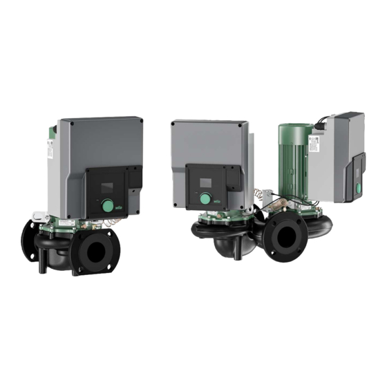
- Page 1 Pioneering for You Wilo-Yonos GIGA2.0-I/-D en Installation and operating instructions · 2203575 • Ed.01/2022-05...
- Page 3 Fig. I Yonos GIGA2.0-I/-D DN 32 ... DN 80...
- Page 4 Fig. II: Yonos GIGA2.0-I / -D DN 100 ... DN 125...
-
Page 5: Table Of Contents
SSM/SBM connection...................................... 38 Connection of digital, analogue and bus inputs............................ 39 Differential pressure sensor connection .............................. 39 Wilo Net connection for twin-head pump function.......................... 40 Turn of the display ...................................... 40 8 Installation of CIF module .............................. 41 9 Commissioning.................................. 42 Filling and venting...................................... - Page 6 12.4 Application and function of the digital control input DI1......................... 68 12.5 Application and function of the analogue inputs AI1 and AI2 ......................... 70 12.6 Application and function of the Wilo Net interface........................... 77 12.7 Application and function of CIF module.............................. 78 13 Display settings..................................
-
Page 7: General Information
All rights reserved. Subject to change Wilo shall reserve the right to change the listed data without notice and shall not be li- able for technical inaccuracies and/or omissions. The illustrations used may differ from the original and are intended as an example representation of the device. -
Page 8: Personnel Qualifications
The operator must confirm and ensure the field of authority, the competence and the monitoring of the personnel. If the personnel do not possess the necessary knowledge, they must be trained and instructed. If required, this can be carried out by the product manufacturer at the operator’s request. WILO SE 2022-05... -
Page 9: Electrical Work
• Do not open the motor! • Dismantling and installation of the rotor may only be carried out by Wilo cus- tomer service! If you have been fitted with a pacemaker, you must not carry out this kind of work! -
Page 10: Installing/Dismantling
This device can be used by children from 8 years of age as well as people with reduced physical, sensory or mental capacities or lack of experience and knowledge if they are supervised or instructed on the safe use of the device and they understand the dangers WILO SE 2022-05... -
Page 11: Intended Use And Misuse
The pump housing is an in-line design; i.e. the flanges on the suction and discharge side are on one axle. All pump housings are provided with pump support feet. Installation on a foundation base is recommended. Installation and operating instructions Wilo-Yonos GIGA2.0-I/-D... - Page 12 Air vent valve Fastening screws from the motor impeller unit, 4x Transport lug, 2x O-ring of drive Twin-head pump flap Twin-head pump flap shim (only DN 100 ... DN 125) Twin-head pump flap axle (only DN 100 ... DN 125) Axle bore screw plug, 2x (only DN 100 ... DN 125) WILO SE 2022-05...
- Page 13 ƒ The drive rating plate is located on the side of the electronic module. The electrical connection must be designed according to the specifications on the drive rating plate. Fig. 2: Rating plates Installation and operating instructions Wilo-Yonos GIGA2.0-I/-D...
-
Page 14: Type Key
Flange connection DN 65 1-20 Continuously adjustable setpoint height 1: Minimum delivery head in m 20: Maximum delivery head in m at Q = 0 m³/h Rated power in kW Variant, e.g. R1 Table 4: Type key For an overview of all product variants, see Wilo-Select/Catalogue. WILO SE 2022-05... -
Page 15: Technical Data
Depending on pump type pA,1 m 20 µPa Nominal diameters DN Yonos GIGA2.0-I/ Yonos GIGA2.0-D: 32/40/50/65/80/100/125 Pipe connections Flanges PN 16 EN 1092-2 Max. permissible operating 16 bar (to + 120 °C) pressure Permissible min./max. fluid -20 °C ... +120 °C Depending on the fluid temperature Installation and operating instructions Wilo-Yonos GIGA2.0-I/-D... -
Page 16: Scope Of Delivery
EMC irregularities can occur under unfavourable circumstances when used in resid- ential environments (C1) with low electrical power in the conducted range. In this case, please contact WILO SE so that together we can find a quick and suitable shutdown measure. -
Page 17: Accessories
Protect the product from moisture, frost and mechanical damage during transport and temporary storage. Leave stickers on the pipe connections so that no dirt and other foreign matter can get into the pump housing. Installation and operating instructions Wilo-Yonos GIGA2.0-I/-D... -
Page 18: Transport For Installation/Dismantling Purposes
Transport and storage To prevent scoring at the bearings and sticking, turn the pump shaft once a week using a socket wrench (see Fig. 5). If a longer storage time is required, contact Wilo for preservation measures. Fig. 5: Turning the shaft WARNING... -
Page 19: Installation
Observe locally applicable accident prevention and safety regulations of profes- sional and trade associations. ƒ Provide protective equipment and ensure that the protective equipment is worn by personnel. ƒ Observe all regulations for working with heavy loads. Installation and operating instructions Wilo-Yonos GIGA2.0-I/-D... -
Page 20: Safety
• Do not open the motor! • Dismantling and installation of the rotor may only be carried out by Wilo cus- tomer service! If you have been fitted with a pacemaker, you must not carry out this kind of work! -
Page 21: Permitted Installation Positions And Change Of The Arrangement Of Components Before The Installation
Only in this position (0°) can condensate be directed away via existing drilled holes, pump lantern and motor (Fig. 9, Item 2). Item 3 and Item 7 are not possible for the Yonos GIGA2.0-I/-D DN 32 ... DN 80. Fig. 9: Permitted installation positions with ho- rizontal motor shaft... - Page 22 CAUTION Material damage due to bent or kinked pressure sensing lines. Improper handling can damage the pressure sensing line. When turning the motor impeller unit, do not bend or kink pressure sensing lines. WILO SE 2022-05...
- Page 23 If the differential pressure sensor is turned, do not interchange the discharge and suction sides on the differential pressure sensor! For additional information about the differential pressure sensor, see “Electrical con- nection” [} 31] section. Installation and operating instructions Wilo-Yonos GIGA2.0-I/-D...
- Page 24 Secure the lantern to the motor flange with the screws (Fig. II, Item 10 and Item 10a). Tighten the screw for the holder (Fig. II, Item 10) only slightly. 14. Push the undamaged or new mechanical seal (Fig. I, Item 25) onto the shaft. WILO SE 2022-05...
- Page 25 Disc between pro- tective plate and lantern Differential Fig. I, Item 8 Special pressure sensor screw Capillary tube Fig. I, Item 5 R ⅛" brass Hand-tight, Installation with screw connec- suitably aligned WEICONLOCK tion to the AN 305‑11 pump housing 90° Installation and operating instructions Wilo-Yonos GIGA2.0-I/-D...
-
Page 26: Preparing The Installation
Mount the pump in a readily accessible place. This makes it easier to complete in- spections, maintenance (e.g. mechanical seal change) or replacement in the future. ƒ Install a device for attaching hoisting gear above the set-up site of large pumps. Total weight of the pump: see catalogue or data sheet. WILO SE 2022-05... - Page 27 Install a swing check valve on the discharge side of each pump! r ≈ 2,5 * (d-2s) 5 x DN Fig. 12: Settling section upstream and downstream of the pump Installation and operating instructions Wilo-Yonos GIGA2.0-I/-D...
- Page 28 1175 1500 1675 1350 2625 1300 1775 1975 1600 3100 1050 1525 Values in acc. with ISO/DIN 5199 – class II (2002) – Appendix B Table 7: Permissible forces and torques on pump flanges in vertical pipe Fig. 14: Load case 16A, EN ISO 5199, Ap- pendix B WILO SE 2022-05...
- Page 29 / E t, EN-GJL 20, EN-GJL = Modulus of elasticity grey cast iron at the selected temperature t, EN-GJL = Modulus of elasticity grey cast iron at 20 °C 20, EN-GJL Installation and operating instructions Wilo-Yonos GIGA2.0-I/-D...
-
Page 30: Twin-Head Pump Installation/Y-Pipe Installation
For twin-head pumps in a twin-head pump housing, the pump on the left in the dir- ection of flow is configured as the main pump at the factory. The differential pres- sure sensor is mounted on this pump. The Wilo Net bus communication cable is also mounted and configured on this pump at the factory. -
Page 31: Installation And Position Of Additional Sensors To Be Connected
• If it is possible for persons to come into contact with the pump or the pumped fluid, the earthed connection must also be fitted with a residual current circuit breaker. • Observe the installation and operating instructions for the accessories! Installation and operating instructions Wilo-Yonos GIGA2.0-I/-D... - Page 32 There are six cable bushings to the terminal room on the electronic module. The cable for the power supply of the electric fan on the electronic module is mounted at the factory. The requirements for electromagnetic compatibility must be observed. WILO SE 2022-05...
- Page 33 Fig. 21) 0 ... 20 mA, 4 ... 20 mA (External setpoint sensor) CIF module Metal with shielding 4, 5, 6 (bus communication) Electrical connection of the 4 (Fig. 20) fan (depending on type) assembled at the factory (24 V DC) Table 9: Cable connections Installation and operating instructions Wilo-Yonos GIGA2.0-I/-D...
- Page 34 Terminal connections for all cable connections in the electronic module correspond to push-in technology. They can be opened with a screwdriver type slot SFZ 1 – 0.6 x 0.6 mm. Length of cable to strip The stripping length of the cables for the terminal connection is 8.5 mm ... 9.5 mm. WILO SE 2022-05...
- Page 35 Fig. 20: Overview of terminals in the module 1 2 3 4 5 6 7 8 9 10 11 12 13 14 15 16 17 Fig. 21: Terminals for analogue inputs, digital inputs and Wilo Net NOTICE AI3 and AI4 (terminals 6 ... 10) and DI2 (terminals 13 and 14) are not assigned.
-
Page 36: Mains Connection
Guide the connection cable through the M25 threaded cable gland (Fig. 18, Item 1). Threaded cable gland with the specified torques. The cables near the screwed connection are to be bent to form a drain loop, to drain any accumulated drips. WILO SE 2022-05... - Page 37 When using a flexible connection cable, use a ring lug for the earth wire (Fig. 24). Fig. 24: Flexible connection cable When using a rigid connection cable, connect the earth wire in a U-shape (Fig. 25). Fig. 25: Rigid connection cable Installation and operating instructions Wilo-Yonos GIGA2.0-I/-D...
-
Page 38: Ssm/Sbm Connection
If a fault is present, the contact at NC is normally open contact. ƒ The converter bridge to NO is closed. The following applies to SBM: ƒ Depending on the configuration, the contact is set to NO or NC. WILO SE 2022-05... -
Page 39: Connection Of Digital, Analogue And Bus Inputs
Only one cable per terminal may be connected to the pump! NOTICE The terminals of the analogue inputs, digital inputs and Wilo Net meet the “safe isolation” requirement (according to EN 61800-5-1) to the mains terminals, the ter- minals SBM and SSM (and vice versa). -
Page 40: Wilo Net Connection For Twin-Head Pump Function
For Yonos GIGA2.0-D, the Wilo Net cable for twin-head pump communication is factory-fitted to both electronic modules. In order to establish the Wilo Net connection, the three H, L, GND terminals must be wired with a communication cable from pump to pump. -
Page 41: Installation Of Cif Module
ƒ For pumps in Y-pipe applications in which the electronic modules are connected to each other through the Wilo Net, only the main pump also requires a CIF module. NOTICE When using CIF module Ethernet, the use of the accessory “Connection M12 RJ45 CIF-Ethernet”... -
Page 42: Commissioning
• Keep a safe distance during operation! • Allow the system and pump to cool to room temperature! • Always wear protective clothing, protective gloves and protective goggles when working. WILO SE 2022-05... - Page 43 When the digital input DI1 is reset to the factory setting, it is active again. The pump will not start without the cable bridge. See “Application and function of the digital con- trol input” [} 68] section. Installation and operating instructions Wilo-Yonos GIGA2.0-I/-D...
-
Page 44: Description Of Operating Elements
A green focus in- dicates navigation in the menu. A yellow focus indicates a configuration of settings. ƒ Green focus: Navigation in menu. ƒ Yellow focus: Change settings. WILO SE 2022-05... - Page 45 Language abbreviations Language English German French Italian Spanish UNIV Universal Fig. 30: Initial settings menu Finnish Swedish Language Portuguese Norwegian UNIV Dutch Danish Polish Hungarian Czech Romanian Fig. 31: Menu language Slovenian Croatian Installation and operating instructions Wilo-Yonos GIGA2.0-I/-D...
- Page 46 Setpoint Settings Diagnostics and measured values P electr = 4 W Factory setting Fig. 32: Main menu 9.4.5 Main menu “Home screen” The selection of the home screen is done by turning the operating button to the “House” symbol. WILO SE 2022-05...
- Page 47 The pump shows the main menu with unchanged setpoint. Fig. 34: Home screen setpoint adjustment Δp- Active influences of the pump status on the display in the home screen for single pumps The active influences are listed from highest to lowest priority: Installation and operating instructions Wilo-Yonos GIGA2.0-I/-D...
-
Page 48: Control Settings
1.1.2 PID PID control 1.1.2 Δp-v Setpoint ∆p-v H set = H target = 1.1.2 Δp-c Setpoint Δp-c H set = H target = 1.1.2 n-c Setpoint n-c n act = n is = 1.1.2 PID Setpoint PID WILO SE 2022-05... - Page 49 If there are more than three submenu items, this is indicated by an arrow above or below the visible menu items. Turn the operating button in the corresponding dir- ection to open the submenu items on the display. Installation and operating instructions Wilo-Yonos GIGA2.0-I/-D...
- Page 50 Press the operating button without selecting another parameter or adjusting an- other value to confirm the setting. Press the Back button to discard the current adjustment and retain the previous setting. The menu changes to the previous setting or previous menu. WILO SE 2022-05...
-
Page 51: Control Functions
The status area is highlighted in red. Control settings 10.1 Control functions The following control functions are available: ƒ Differential pressure ∆p-v ƒ Differential pressure Δp-c ƒ Speed constant (n-const) ƒ PID control Installation and operating instructions Wilo-Yonos GIGA2.0-I/-D... -
Page 52: Selecting A Control Mode
Dual pump management Display settings Additional settings To choose a control mode, select the following in succession: Control settings Universal Display text Settings Control mode Control settings 1.1.1 Control mode Setpoint Δp-v Emergency operation Fig. 40: Control mode WILO SE 2022-05... - Page 53 If the control mode constant speed n-c is selected, the submenu “Setpoint n-c” opens in the “Control setting” menu. The desired speed can be set as the setpoint. After confirming the setpoint, the “Control setting” menu opens again. Installation and operating instructions Wilo-Yonos GIGA2.0-I/-D...
-
Page 54: Setting The Setpoint Source
A CIF module can only be selected as a setpoint source if a CIF module is installed. The menu item cannot otherwise be selected. If the setpoint is set via the analogue input AI2, the analogue input can be con- figured in the “Settings” menu. WILO SE 2022-05... -
Page 55: Emergency Operation
The motor of the pump can be switched on and off in the “Settings” menu . To do this, select the following in succession: Universal Display text Setpoint n-c Settings Setpoint source Control settings 1.1.15 Pump ON/OFF Pump ON/OFF Switched off Switched on Fig. 48: Control setting pump ON/OFF Installation and operating instructions Wilo-Yonos GIGA2.0-I/-D... -
Page 56: Configuration Storage/Data Storage
24 h at the latest. Both pumps run at the time of pump changeover so that operation is not interrupted. The operated pump can be replaced at least every 1 hour and can be set in length increments up to a maxi- mum of 36 hours. WILO SE 2022-05... -
Page 57: Twin-Head Pump Behaviour
Wilo Net must be installed with cable between the pumps when connecting two single pumps of the same type to a twin-head pump. Then set the termination as well as the Wilo Net address in the menu under “Set- tings/external interfaces/Wilo Net setting”. Then, in the “Dual pump management”... - Page 58 The following settings are possible with an existing twin-head pump connection: ƒ Disconnect twin-head pump. ƒ Twin-head pump function ƒ Set pump cycling. ƒ Pump housing type NOTICE With a factory-supplied twin-head pump, the twin-head pump connection is pre- configured and active. WILO SE 2022-05...
- Page 59 Pump housing type Dual pump management 1.4.1 Connecting twin-head pump Fig. 51: Dual pump management menu The Wilo Net address of the twin-head pump partner must first be set for both pumps Connecting twin-head pump of the twin-head pump. Example: Twin-head pump partner Pump I is assigned the Wilo Net address 1, pump II the Wilo Net address 2.
- Page 60 1.4.3.1 Main/reserve 1.4.3.2 Peak-load operation Fig. 55: Twin-head pump function menu NOTICE When switching the twin-head pump function, different parameters of the pump are fundamentally changed. The pump is then automatically restarted. The main menu then opens again. WILO SE 2022-05...
- Page 61 Twin-head pump function ƒ Single pump hydraulics ƒ Twin-head pump hydraulics I (left in flow direction) ƒ Twin-head pump hydraulics II (right in flow direction) Pump cycling Pump housing type Fig. 57: Dual pump management menu Installation and operating instructions Wilo-Yonos GIGA2.0-I/-D...
-
Page 62: Display For Twin-Head Pump Operation
Partner pump without a mounted differential pressure sensor: symbol SL in set- point display field Two pump symbols are displayed in twin-head pump operation in the “Active influ- ences” area. This is what they mean: Case 1 – main/standby operation: only the main pump is running. WILO SE 2022-05... - Page 63 This pump head is active standby operation. This pump head is active in control mode. Main/standby operation: Twin-head pump is set in main/ Partner pump active standby operation. The pump partner is active in control mode. Installation and operating instructions Wilo-Yonos GIGA2.0-I/-D...
-
Page 64: Communication Interfaces: Setting And Function
1.3.2 Control input 1.3.3 Analogue input (AI1) 1.3.4 Analogue input (AI2) 1.3.5 Wilo Net setting NOTICE The submenus for setting the analogue inputs are only available depending on the selected control mode. 12.1 Menu overview of “External inter- Universal Display text faces”... - Page 65 ƒ If there is a fault, the contact at NC is open. The converter bridge to NO is closed. To do this, select the following in the menu: Universal Display text Settings External interfaces Installation and operating instructions Wilo-Yonos GIGA2.0-I/-D...
- Page 66 (collective run signal). Depending on the configuration, the contact is set to NO or NC. To do this, select the following in the menu: Universal Display text Settings External interfaces 1.3.1 Relay output (SSM/SBM) WILO SE 2022-05...
-
Page 67: Ssm/Sbm Relay Forced Control
Help text Forced control Normal SSM: Depending on the SSM configuration, fault and warnings influence the SSM relay switching status. SBM: Depending on the SBM configuration, the pump status influences the SBM relay switching status. Installation and operating instructions Wilo-Yonos GIGA2.0-I/-D... -
Page 68: Application And Function Of The Digital Control Input Di1
The control input does not have a function. External OFF Contact open: Pump is switched off. Not used Factory setting: Contact closed: Pump is switched on. External OFF Table 25: Control input function DI1 Fig. 64: Digital input menu function WILO SE 2022-05... - Page 69 Active Active Override Override OFF (DI1) OFF (DI1/2) Not act- OK; normal Active operation Override OFF (DI1/2) Active Not act- OK; normal Override operation OFF (DI1) Installation and operating instructions Wilo-Yonos GIGA2.0-I/-D...
- Page 70 AI1 put AI2 Δp-v Configured as actual value Not configured input Can be used as a setpoint ƒ Type of use: Differen- input tial pressure sensor Configurable: ƒ Signal type ƒ Sensor measurement range ƒ Sensor position WILO SE 2022-05...
- Page 71 When setting the control mode, the type of use of analogue input AI1 as an actual value input (see Table 28) is automatically preconfigured. To set the signal type, select the following in the menu: Installation and operating instructions Wilo-Yonos GIGA2.0-I/-D...
- Page 72 The actual value of the differential pressure runs linearly between the analogue signals 2 V and 10 V. This corresponds to 0 % ... 100 % of the sensor measuring range. (See diagram Fig. 70). Fig. 70: Behaviour of analogue input AI 1: Sensor value with signal type 2 ... 10 V / 4 ... 20 WILO SE 2022-05...
- Page 73 The applied analogue signal of 2 V or 4 mA represents the actual value of the differen- tial pressure at “0 %”. The applied analogue signal of 10 V or 20 mA represents the ac- tual value of the differential pressure at “100 %”. (See diagram Fig. 70). Installation and operating instructions Wilo-Yonos GIGA2.0-I/-D...
- Page 74 The setpoint to which the pump controls is specified according to “Control settings” section. The adjustment is made in menu “Control setting” [} 51], “Set setpoint source” [} 54]. “Internal setpoint” must be activated. The “Cable break detection” function is not active. WILO SE 2022-05...
- Page 75 The applied analogue signal of 5 V or 10 mA repres- ents the setpoint (for instance the speed) at “0 %”. The applied analogue signal of 10 V or 20 mA represents the setpoint of the differential pressure at “100 %”. (See diagram Fig. 76). Installation and operating instructions Wilo-Yonos GIGA2.0-I/-D...
- Page 76 The setpoint source must be adjusted again to “Internal setpoint”. The pairing between external source and setpoint is marked both in the home screen, and in the setpoint editor in blue. The status LED also becomes blue. WILO SE 2022-05...
-
Page 77: Application And Function Of The Wilo Net Interface
Communication interfaces: Setting and function 12.6 Application and function of the Wilo Net is a bus system that Wilo products (participants) can use to communicate with Wilo Net interface each other. Application for: ƒ twin-head pumps consisting of two participants Bus topology: The bus topology consists of several pumps (participants) connected in series. -
Page 78: Application And Function Of Cif Module
Display settings Twin-head pump example: ƒ Pump head left (l) – Wilo Net termination: ON – Wilo Net address: 1 ƒ Pump head right (II) – Wilo Net termination: ON – Wilo Net address: 2 12.7 Application and function of CIF... - Page 79 Display settings UNIV 1.5.2 Language English English Deutsch German Français French • • • • Fig. 82: Menu language • • 13.3 Unit The units of the physical values can be set under “Settings”, “Display settings”. Installation and operating instructions Wilo-Yonos GIGA2.0-I/-D...
-
Page 80: Additional Settings
The active key lock can be identified in the Home screen by a lock symbol Additional settings General settings can be changed under “Settings”, “Additional settings”. The following table gives an overview of the “Additional settings” menu: Universal Display text Settings Additional settings 1.6.1 Pump kick 1.6.1.1 Pump kick: ON/OFF WILO SE 2022-05... -
Page 81: Ramp Times For Setpoint Change
For this purpose, the pump must be switched on at the control side before the mains disconnection. 14.2 Ramp times for setpoint change The ramp times of the pumps can be set in the menu “Settings”, “Additional set- tings”. Installation and operating instructions Wilo-Yonos GIGA2.0-I/-D... -
Page 82: Automatic Pwm Frequency Reduction
Service information 2.1.3 Overview of relay output (SSM/SBM) Relay function:SSM Relay function: SSM Relay function:SBM Relay function: SBM Forced control:Yes Forced control: Yes Fig. 86: Diagnostics and measured values Forced control:No Forced control: No Current status:Energized Current status: Energized WILO SE 2022-05... - Page 83 H is = n act = n is = P electr = P electr = U mains = U mains = 2.2.2 Statistical data W electr = W electr = Operating hours = Operating hours = Installation and operating instructions Wilo-Yonos GIGA2.0-I/-D...
-
Page 84: Overview Of The Ssm/Sbm Relay Status
Diagnostics and measured values WICD = Wilo Communication ID (Communication address of the twin-head pump partner) 15.1 Diagnostics help There are functions for diagnosis and maintenance of electronics and interfaces in the menu “Diagnostics and measured values”, “Diagnostics help”. The following table provides an overview of the “Diagnostics help” menu:... -
Page 85: Overview Of The Analogue Inputs Ai1 And Ai2
ƒ Current measured value 15.6 Overview of the twin-head pump connection You can read status information on the twin-head pump connection in the menu “Diagnostics and measured values”. To do this, select the following: Installation and operating instructions Wilo-Yonos GIGA2.0-I/-D... -
Page 86: Overview Of The Pump Cycling Status
Partner Address: Partner address: Partner Name: Partner name: WICD = Wilo Communication ID (Communication address of the twin-head pump partner) NOTICE The twin-head pump connection overview is only available if a twin-head pump connection has been previously configured (see “Dual pump management” [} 56] section). -
Page 87: Reset
. To do this, select the following: Universal Display text Factory setting Factory setting Reset to Back to factory settings factory setting Confirm Confirm (settings will be lost!) CANCEL Cancel Fig. 97: Resetting to factory setting Installation and operating instructions Wilo-Yonos GIGA2.0-I/-D... - Page 88 Type of use: differential pressure sensor Sensor position: pump flange Signal type: 2 ... 10 V not configured not configured Wilo Net Wilo Net termination switched on switched on Wilo Net address Twin-head pump Twin-head pump Main pump: 1 Main pump: 1...
-
Page 89: Faults, Causes And Remedies
The pump does not pump if an error has occurred. If the pump identifies as part of permanent monitoring that the cause of the error no longer applies, the error mes- sage is revoked and operation resumes. Installation and operating instructions Wilo-Yonos GIGA2.0-I/-D... - Page 90 Remove deposits and for- eign substances. Additional information on causes and remedies: In addition to deposits and foreign substances in the system, the pump shaft can also be blocked. WILO SE 2022-05...
- Page 91 The pump cannot determine which of the two components is faulty. Contact service. Electronic module is de- Electronic module is Electronic module is de- fective. defective. fective. Additional information about causes and remedy: Contact service. Table 34: Error messages Installation and operating instructions Wilo-Yonos GIGA2.0-I/-D...
-
Page 92: Warning Messages
Check power control of the erated flow through the cause flow in the other pumps. pump in the direction of pump’s direction of flow. flow. Additional information about causes and remedy: The pump can start despite flow. WILO SE 2022-05... - Page 93 Additional information about causes and remedy: Pump function slightly impaired. The motor head meets the pump function up to the performance limit. Installation and operating instructions Wilo-Yonos GIGA2.0-I/-D...
- Page 94 Communication between display and electronic module in- and electronic module interrupted between display and terrupted. electronic module inter- Please check in user manual. rupted Please check op- Please check user manual erating manual Please check operating manual Fig. 99: Warning W573 WILO SE 2022-05...
-
Page 95: Maintenance
Installation/dismantling work: The installation/dismantling must be carried out by a qualified technician who is trained in the use of the necessary tools and fixation materials. It is recommended to have the pump serviced and checked by the Wilo customer ser- vice. DANGER... -
Page 96: Air Supply
18.2 Maintenance tasks DANGER Risk of fatal injury from falling parts! Falling pumps or individual pump components may result in life-threatening injuries! • During installation work, secure pump components against falling down with suitable lifting gear. WILO SE 2022-05... - Page 97 A regular visual inspection is required. If leakage is clearly visible, replace the gasket. For further information, see also Wilo Consulting guide for glanded pumps. Wilo offers a repair kit which contains the necessary parts for replacement. NOTICE The magnets inside the motor do not pose a risk to persons with pacemakers provided that the motor is not opened and the rotor is not dismantled.
- Page 98 In order to avoid tipping, the motor impeller unit may have to be supported with suitable lifting equipment. This is especially the case if no mounting bolts are used. 24. Release the two non-detachable screws from the protective plate (Fig. II, Item 27) and remove the protective plate. WILO SE 2022-05...
- Page 99 17. Once the lantern guide has firmly engaged, (about 15 mm before the end position), there is no longer any danger of tipping or tilting. After securing the motor impeller unit with at least one screw (Fig. II, Item 29), the fixation can be removed from the transport lugs. Installation and operating instructions Wilo-Yonos GIGA2.0-I/-D...
- Page 100 18.2.2 Replacing the motor/drive Increased bearing noises and unusual vibrations indicate bearing wear. The bearings or motor must then be replaced. The drive may only be replaced by the Wilo customer ser- vice! DANGER Risk of fatal electrical shock! Generator or turbine operation during...
- Page 101 To dismantle the electronic module, carry out steps 1 ... 5 according to section “Changing the mechanical seal” [} 97]. Remove the screws (Fig. I, Item 4) and remove the electronic module from the mo- tor. Replace the O-ring (Fig. I, Item 31). Installation and operating instructions Wilo-Yonos GIGA2.0-I/-D...
- Page 102 1 ... 5 in the section “Replacing the mechanical seal” [} 97]. Dismantling the fan Open the cover of the electronic module. Fig. 102: Open the cover of the electronic module Remove the connection cable of the module fan. Fig. 103: Loosen the connection cable of the module fan WILO SE 2022-05...
-
Page 103: Spare Parts
Install the module fan in reverse order. Spare parts Obtain genuine spare parts only from a qualified specialist or Wilo customer service. To avoid queries and order errors, please provide all pump and drive rating plate data with every order. Pump rating plate see Fig. 2, Item 1, drive rating plate see Fig. 2, Item 2. -
Page 104: Disposal
Please consult your local municipality, the nearest waste disposal site, or the dealer who sold the product to you for information on proper disposal. See www.wilo‑recycling.com for more information about recycling. Subject to change without prior notice! WILO SE 2022-05... - Page 116 Local contact at www.wilo.com/contact WILO SE Wilopark 1 44263 Dortmund Germany T +49 (0)231 4102-0 F +49 (0)231 4102-7363 wilo@wilo.com Pioneering for You www.wilo.com...
Need help?
Do you have a question about the Yonos GIGA2.0-I and is the answer not in the manual?
Questions and answers