
Related Manuals for Wilo EMU TR 50-2


Summary of Contents for Wilo EMU TR 50-2
- Page 1 Pioneering for You Wilo-EMU TR/TRE 50-2 ... 120-1 en Installation and operating instructions · 6074714 • Ed.01/2019-01...
-
Page 3: Table Of Contents
Operation in an explosive atmosphere ................................ 28 Before switching on...................................... 28 Switch on and off...................................... 28 During operation ...................................... 29 8 Shut-down/dismantling................................. 29 Personnel qualifications.................................... 29 Operator responsibilities.................................... 30 Shut-down........................................ 30 Removal.......................................... 30 Installation and operating instructions Wilo-EMU TR/TRE 50-2 ... 120-1... - Page 4 12.1 Oils and lubricants...................................... 44 12.2 Protective clothing ...................................... 44 12.3 Information on the collection of used electrical and electronic products.................... 44 13 Appendix.................................... 44 13.1 Tightening torques ...................................... 44 13.2 Operation with frequency converter................................ 45 13.3 Ex rating ........................................... 45 WILO SE 2019-01...
-
Page 5: General Information
Warranty The specifications in the current “General Terms and Conditions” apply to the warranty and the warranty period. These can be found at www.wilo.com/legal Any deviations must be contractually agreed and shall then be given priority. Claim to warranty... - Page 6 Danger of electric voltage Danger of bacterial infection Danger – explosive atmosphere General warning symbol Warning of cutting injuries Warning of hot surfaces Warning of high pressure Warning of suspended loads Personal protective equipment: wear a safety helmet WILO SE 2019-01...
-
Page 7: Personnel Qualifications
The following monitoring devices must be provided on-site: Circuit breaker The size and switching characteristics of the circuit breakers must conform to the rated current of the connected product. Observe local regulations. Installation and operating instructions Wilo-EMU TR/TRE 50-2 ... 120-1... -
Page 8: Use In Fluids Hazardous To Health
Keep the working area free of ice. ƒ Keep the working area free of any objects lying around. ƒ If the weather conditions mean it is no longer possible to work safely, stop work. ƒ Keep unauthorised persons away from the working area. WILO SE 2019-01... -
Page 9: During Operation
To avoid injuries, allow the motor to cool down to the am- bient temperature before carrying out any work! ƒ When the pressure has been completely released, fully unscrew the screw plug. Installation and operating instructions Wilo-EMU TR/TRE 50-2 ... 120-1... -
Page 10: Operating Fluid
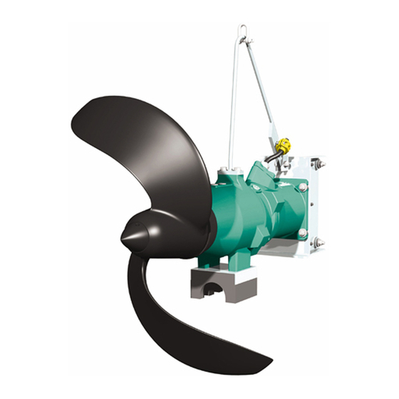
Pre-chamber Fig. 1: Overview of the submersible mixer 4.1.1 Propeller Propeller made of solid or composite material, clogging-free thanks to backward- curved incoming flow edge. NOTICE! The propeller must not emerge during opera- tion. Observe specified minimum water immersion! WILO SE 2019-01... - Page 11 ** = depending on the motor type and motor capacity fluid temperatures up to 60 °C (140 °F) are possible. 4.1.4 Seal The system is sealed by a 3-chamber system: ƒ Pre-chamber ƒ Gear chamber ƒ Sealing chamber Installation and operating instructions Wilo-EMU TR/TRE 50-2 ... 120-1...
-
Page 12: Monitoring Devices
The pre-chamber can be equipped with an external pencil electrode. The electrode re- gisters fluid ingress through the mechanical seal on the fluid side. An alarm or deactiva- tion of the mixer can therefore occur via the system controller. WILO SE 2019-01... -
Page 13: Operating Modes
The following is an overview of the abbreviations and associated data on the rating plate: Rating plate Value designation Mixer type P-Typ Motor type M-Typ Serial number Date of manufacture* Speed Max. fluid temperature Installation and operating instructions Wilo-EMU TR/TRE 50-2 ... 120-1... -
Page 14: Type Key
W = abbreviation for week ƒ ww = calendar week Type key Example: Wilo-EMU TRE 90-2.20-4/12REx X Submersible mixer, horizontal: TR = mixer with standard asynchronous motor TRE = mixer with asynchronous motors of motor efficiency class IE3/IE4 x10 = nominal propeller diameter in mm... -
Page 15: Transport
The stability of the lifting equipment must be ensured during operation. ƒ When using lifting equipment, a second person must be present to coordinate the procedure if required (e.g. if the operator’s field of vision is blocked). Fig. 2: Attachment point Installation and operating instructions Wilo-EMU TR/TRE 50-2 ... 120-1... -
Page 16: Storage
Evidence must be presented in accordance with BGV D8 or ap- plicable local regulations. ƒ Operator responsibilities Observe the locally applicable accident prevention and safety regulations of trade associations. ƒ Observe all regulations for working with heavy loads and under suspended loads. WILO SE 2019-01... -
Page 17: Installation Types
Danger of (serious) injuries during work. Wear the following protective equipment: • Safety gloves for protection against cuts • Safety shoes • Safety harness • Safety helmet must be worn if lifting equipment is used! Installation and operating instructions Wilo-EMU TR/TRE 50-2 ... 120-1... - Page 18 The propeller blade has sharp edges! Sharp edges can form on the propeller blades. There is a risk of limbs being severed. Wear safety gloves to protect against cuts. ‡ The mixer is not connected to the mains! WILO SE 2019-01...
- Page 19 7. Clean the drain hole screw plug, replace the seal ring and screw it back in. Max. tightening torque: 8 Nm (5.9 ft·lb)! 8. Pour the operating fluid through the filler hole. ⇒ Comply with the specifications for the operating fluid type and quantity! Installation and operating instructions Wilo-EMU TR/TRE 50-2 ... 120-1...
- Page 20 Bevel the basin edge if necessary! 7. Apply corrosion protection (e.g. Sikaflex): - Sealing joint between mounting bracket and structure. - Fill holes in the baseplate of the mounting bracket. - Fill scratches in the mounting bracket. WILO SE 2019-01...
- Page 21 NOTICE! The frame must be perpendicular to the guide pipe. If the frame is not perpendicular to the guide pipe, adjust the reach of the hoisting gear. Fig. 7: Swivel the mixer over the basin Installation and operating instructions Wilo-EMU TR/TRE 50-2 ... 120-1...
- Page 22 6. Set the desired angle and install a screw to secure the lowering device against fur- ther adjustments. ▶ Installation is complete. Lay the connection cable and make the electrical connec- tion. Fig. 9: Mixer set down on the fixed limit stop WILO SE 2019-01...
-
Page 23: Electrical Connection
In case of sensitive mains, make provision for the installation on- site of other protective equipment (e.g. overvoltage, undervoltage or phase failure re- lay, etc.). Installation and operating instructions Wilo-EMU TR/TRE 50-2 ... 120-1... - Page 24 Electrical connection must always be carried out by a qualified electrician! NOTICE! The individual wires are designated according to the connection diagram. Do not cut the wires! There is no additional assignment between the wiring diagram and connection diagram. WILO SE 2019-01...
- Page 25 Connection values: max. 250 V (AC), 2.5 A, cos φ = 1 Wiring diagram for bimetallic strip Temperature limiter 20, 21 Bimetallic strip connection Temperature controller and limiter High temperature connection Centre terminal Low temperature connection Installation and operating instructions Wilo-EMU TR/TRE 50-2 ... 120-1...
- Page 26 To avoid power dissipation, bypass the electronic starter (soft start) once normal op- eration is reached. 6.5.6 Operation with frequency con- Operation on the frequency converter is permitted. Refer to the appendix for the relev- verter ant requirements! WILO SE 2019-01...
-
Page 27: Commissioning
If the direction of rotation is incorrect, change the connection as follows: ƒ Direct starting: swap two phases. ƒ Star-delta starting: Swap connections of two windings (e.g. U1/V1 and U2/V2). NOTICE! After changing this connection, check the direction of rotation again! Installation and operating instructions Wilo-EMU TR/TRE 50-2 ... 120-1... -
Page 28: Operation In An Explosive Atmosphere
The mixer must switch on and off using a separate operating point (on/off switch, switchgear) set by the customer. During the start process, the rated current is exceeded for several seconds. Current consumption continues to be slightly above the rated current until the operating tem- WILO SE 2019-01... -
Page 29: During Operation
If the fluid level drops below the minimum immersion level, switch off the mixer. Shut-down/dismantling ƒ Personnel qualifications Operation/control: Operating personnel must be instructed in the functioning of the complete system. Installation and operating instructions Wilo-EMU TR/TRE 50-2 ... 120-1... -
Page 30: Operator Responsibilities
Risk of fatal injury if the mixer is used in fluids hazardous to health. • Decontaminate the mixer after dismantling and before carrying out any other work. • Observe the specifications provided by work regulations. The operator must make sure that personnel have received and read work regulations. WILO SE 2019-01... - Page 31 5. Set the mixer down on a pallet, secure it against slipping and lift it out of the oper- ating space. ▶ Removal is complete. Clean and disinfect the mixer thoroughly. 8.4.2 Using a lowering device ‡ Mixer decommissioned. ‡ Protective equipment put on according to work regulations. Installation and operating instructions Wilo-EMU TR/TRE 50-2 ... 120-1...
-
Page 32: Maintenance And Repair
NOTICE Use only properly functioning lifting equipment! Use only properly functioning lifting equipment to lift and lower the mixer. Ensure that the mixer does not become jammed during lifting and lowering. Do not exceed WILO SE 2019-01... -
Page 33: Personnel Qualifications
To ensure reliable operation, maintenance tasks must be carried out regularly. Depend- ing on the real ambient temperatures, maintenance intervals different to those men- tioned in the contract can be established! If strong vibrations occur during operation, Installation and operating instructions Wilo-EMU TR/TRE 50-2 ... 120-1... -
Page 34: Maintenance Measures
9.5.2 Visual inspection of the connec- Check connection cable for: tion cable ƒ Bubbles ƒ Cracks ƒ Scratches ƒ Abrasion ƒ Pinch points ƒ Changes caused by chemical corrosion WILO SE 2019-01... - Page 35 Maintenance and repair If damage to the connection cable is identified, decommission the mixer immediately! Have the connection cable replaced by Wilo customer service. Only start the mixer up again once the damage has been properly remedied! CAUTION! Water can enter into the mixer if the connection cable is damaged! Water ingress leads to the mixer being written off.
- Page 36 10.Restore corrosion protection: Seal screw plug, e.g. with Sikaflex. 9.5.8 General overhaul The following components are checked for wear and damage as part of general main- tenance: ƒ Motor bearings ƒ Gear bearing and planetary gear speed WILO SE 2019-01...
-
Page 37: Repairs
Which repair work may be carried Propeller replacement ƒ Replacement of mechanical seal on the fluid side. ƒ Replace the handle grip. ƒ Replacement of the frame. ƒ Replacement of the mounting bracket for ground installation. Installation and operating instructions Wilo-EMU TR/TRE 50-2 ... 120-1... - Page 38 9. Turn the propeller by hand and check that it rotates easily. 10.Place a new O-ring in the hub screw cap. 11.Screw on the hub screw cap. ▶ Propeller is changed. Check the oil quantity in the pre-chamber and if necessary, top up oil. WILO SE 2019-01...
- Page 39 6. Press in a new stationary ring for the mechanical seal into the housing using an as- sembly unit. CAUTION! Do not tilt the stationary ring when pushing it in. If the Installation and operating instructions Wilo-EMU TR/TRE 50-2 ... 120-1...
- Page 40 - Screw on and fully tighten the hexagon nut. Max. tightening torque: see ap- pendix. 10.Check the shackle position! Attach the lifting equipment to shackles. The mixer must remain horizontal during lifting. Move shackles if the mixer tilts. ▶ Handle grip changed. WILO SE 2019-01...
- Page 41 NOTICE! Note height grid! The propeller must not come into contact with the floor! 8. Place the mixer on the hexagon head screws. 9. Place washers on the hexagon head screws. 10.Attach and firmly tighten hexagon nuts. Max. tightening torque: see appendix. Installation and operating instructions Wilo-EMU TR/TRE 50-2 ... 120-1...
-
Page 42: Faults, Causes And Remedies
1. Mains connection interrupted or short-circuit/earth fault in the cable or motor winding. ⇒ Have the connection and motor checked by a qualified electrician and replace if necessary. 2. Tripping of fuses, of the motor protection switch or the monitoring device. WILO SE 2019-01... - Page 43 2. Propeller clogged. ⇒ Clean propeller and mechanical seal. ⇒ Check the pre-treatment. 3. The connection only has two phases. ⇒ Have the connection checked and corrected by a qualified electrician. Installation and operating instructions Wilo-EMU TR/TRE 50-2 ... 120-1...
-
Page 44: Spare Parts
Observe the locally applicable regulations! Please consult your local municipality, the nearest waste disposal site, or the dealer who sold the product to you for information on proper disposal. Further recycling informa- tion can be found at www.wilo-recycling.com. Appendix 13.1... -
Page 45: Operation With Frequency Converter
13.3 Ex rating This section contains further information on the operation of the mixer in an explosive atmosphere. All personnel must read this section. This section applies only to Ex-rated mixers! Installation and operating instructions Wilo-EMU TR/TRE 50-2 ... 120-1... - Page 46 All monitoring devices outside the “spark-proof areas” must be connected via an in- trinsically safe circuit (e.g. Ex-i relay XR-4...). ƒ The voltage tolerance may not be higher than max. ±10 %. Overview of possible monitoring devices: − − − − − − Motor compartment/sealing chamber Pre-chamber (external pencil electrode) WILO SE 2019-01...
- Page 47 Speed/torque curves required are available on request! ƒ Observe additional measures with regard to EMC regulations (choice of frequency converter, filters, etc.). ƒ Never exceed the rated current or rated speed of the motor. Installation and operating instructions Wilo-EMU TR/TRE 50-2 ... 120-1...
- Page 48 If the housing coating has to be repaired, the maximum coat thickness is 2 mm (0.08 in)! 13.3.6.2 Replacing the connection cable Changing the connection cable is strictly prohibited! 13.3.6.3 Changing the mechanical seal Changing the seal on the motor side is strictly prohibited! WILO SE 2019-01...
- Page 51 WILO Pompa Sistemleri Jakarta Timur, 13950 Sistemas Hidraulicos Lda. San. ve Tic. A.S¸ T +62 21 7247676 4475-330 Maia 34956 İstanbul citrawilo@cbn.net.id T +351 22 2080350 T +90 216 2509400 bombas@wilo.pt wilo@wilo.com.tr Further subsidiaries, representation and sales offices on www.wilo.com Oktober 2018...
- Page 52 WILO SE Nortkirchenstr. 100 44263 Dortmund Germany T +49 (0)231 4102-0 T +49 (0)231 4102-7363 wilo@wilo.com Pioneering for You www.wilo.com...
Need help?
Do you have a question about the EMU TR 50-2 and is the answer not in the manual?
Questions and answers