
Subscribe to Our Youtube Channel
Related Manuals for Wilo EMU TR Series


Summary of Contents for Wilo EMU TR Series
- Page 1 Pioneering for You Wilo-EMU TR 14-40 en Installation and operating instructions · 6074708 • Ed.02/2019-01...
-
Page 3: Table Of Contents
Operation in an explosive atmosphere ................................ 28 Before switching on...................................... 29 Switch on and off...................................... 29 During operation ...................................... 30 8 Shut-down/dismantling................................. 30 Personnel qualifications.................................... 30 Operator responsibilities.................................... 31 Shut-down........................................ 31 Removal.......................................... 31 Installation and operating instructions Wilo-EMU TR 14-40... - Page 4 12.1 Oils and lubricants...................................... 43 12.2 Protective clothing ...................................... 43 12.3 Information on the collection of used electrical and electronic products.................... 43 13 Appendix.................................... 43 13.1 Tightening torques ...................................... 43 13.2 Operation with frequency converter................................ 44 13.3 Ex rating ........................................... 44 WILO SE 2019-01...
-
Page 5: General Information
Warranty The specifications in the current “General Terms and Conditions” apply to the warranty and the warranty period. These can be found at www.wilo.com/legal Any deviations must be contractually agreed and shall then be given priority. Claim to warranty... - Page 6 Danger of electric voltage Danger of bacterial infection Danger – explosive atmosphere General warning symbol Warning of cutting injuries Warning of hot surfaces Warning of high pressure Warning of suspended loads Personal protective equipment: wear a safety helmet WILO SE 2019-01...
-
Page 7: Personnel Qualifications
Monitoring devices The following monitoring devices must be provided on-site: Circuit breaker The size and switching characteristics of the circuit breakers must conform to the rated current of the connected product. Observe local regulations. Installation and operating instructions Wilo-EMU TR 14-40... -
Page 8: Use In Fluids Hazardous To Health
Keep the working area free of ice. ƒ Keep the working area free of any objects lying around. ƒ If the weather conditions mean it is no longer possible to work safely, stop work. ƒ Keep unauthorised persons away from the working area. WILO SE 2019-01... -
Page 9: During Operation
To avoid injuries, allow the motor to cool down to the am- bient temperature before carrying out any work! ƒ When the pressure has been completely released, fully unscrew the screw plug. Installation and operating instructions Wilo-EMU TR 14-40... -
Page 10: Operating Fluid
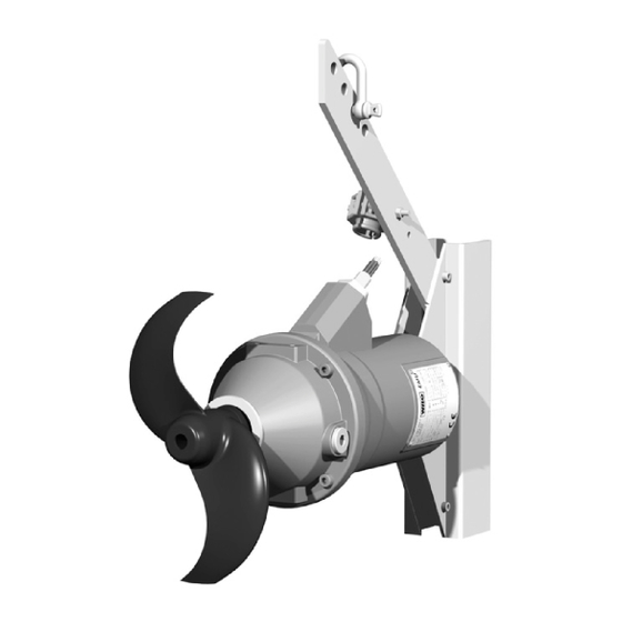
Attachment point Fig. 1: Overview of the submersible mixer 4.1.1 Propeller Propeller made of solid material with backward-curved incoming flow edge and paten- ted helical hub. NOTICE! The propeller must not emerge during operation. Observe specified minimum water immersion! WILO SE 2019-01... - Page 11 The seal on the motor side involves either a rotary shaft seal or a mechanical seal. The seal housing is filled with white oil and absorbs leakage from the seal on the fluid side. Installation and operating instructions Wilo-EMU TR 14-40...
-
Page 12: Monitoring Devices
This allows the meas- urement of two temperatures. When the low temperature is reached, an automatic re- activation can be initiated after cooling the motor. When the high temperature is reached, the unit must deactivate with reactivation lock. WILO SE 2019-01... -
Page 13: Operating Modes
Category: Class 1Division 1 Rating plate The following is an overview of the abbreviations and associated data on the rating plate: Rating plate Value designation Mixer type P-Typ Motor type M-Typ Serial number Installation and operating instructions Wilo-EMU TR 14-40... -
Page 14: Type Key
W = abbreviation for week ƒ ww = calendar week Type key Example: Wilo-EMU TR 36.95-6/16REx S17 Submersible mixer, horizontal: TR = mixer with standard asynchronous motor TRE = mixer with asynchronous motors of motor efficiency class IE3/IE4 x10 = nominal propeller diameter in mm... -
Page 15: Transport
The stability of the lifting equipment must be ensured during operation. ƒ When using lifting equipment, a second person must be present to coordinate the procedure if required (e.g. if the operator’s field of vision is blocked). Fig. 2: Attachment point Installation and operating instructions Wilo-EMU TR 14-40... -
Page 16: Storage
Evidence must be presented in accordance with BGV D8 or ap- plicable local regulations. ƒ Operator responsibilities Observe the locally applicable accident prevention and safety regulations of trade associations. ƒ Observe all regulations for working with heavy loads and under suspended loads. WILO SE 2019-01... -
Page 17: Installation Types
Danger of (serious) injuries during work. Wear the following protective equipment: • Safety gloves for protection against cuts • Safety shoes • Safety harness • Safety helmet must be worn if lifting equipment is used! Installation and operating instructions Wilo-EMU TR 14-40... - Page 18 The propeller blade has sharp edges! Sharp edges can form on the propeller blades. There is a risk of limbs being severed. Wear safety gloves to protect against cuts. ‡ The mixer is not connected to the mains! WILO SE 2019-01...
- Page 19 7. Clean the screw plug (-), replace the seal ring and screw it back in. Max. tightening torque: 8 Nm (5.9 ft·lb)! 8. Pour new operating fluid in through the hole for the screw plug (+). ⇒ Comply with the specifications for the operating fluid type and quantity! Installation and operating instructions Wilo-EMU TR 14-40...
- Page 20 Bevel the basin edge if necessary! 7. Apply corrosion protection (e.g. Sikaflex): - Sealing joint between mounting bracket and structure. - Fill holes in the baseplate of the mounting bracket. - Fill scratches in the mounting bracket. WILO SE 2019-01...
- Page 21 Mixer Cable bracket clearance 550 mm (20 in) TR 14 550 mm (20 in) TR 16 550 mm (20 in) TR 21 750 mm (30 in) TR 22 550 mm (20 in) TR 28 750 mm (30 in) TR 36 750 mm (30 in) TR 40 Installation and operating instructions Wilo-EMU TR 14-40...
- Page 22 NOTICE! The guide rollers are in contact with the guide pipe. 3. Version with quick-release axles: Fig. 9: Mixer on the lowering device Lower the mixer until the frame is below the upper holder. Install the quick-release axles and plastic rollers and secure them with linchpins! WILO SE 2019-01...
-
Page 23: Electrical Connection
Risk of death due to electrocution! Improper conduct when carrying out electrical work can lead to death due to electric shock! Electrical work must be carried out by a qualified electrician in accordance with the locally applicable regulations. Installation and operating instructions Wilo-EMU TR 14-40... - Page 24 For further measurements: Value must be greater than 2 MΩ. 6.5.2.2 Test the resistor of the temper- Measure the resistor of the temperature sensors with an ohmmeter. The following ature sensor measured values must be complied with: ƒ Bimetallic strip: Measured value = 0 Ohm (passage). WILO SE 2019-01...
- Page 25 • Note the additional information in the chapter on potentially explosive areas found in the appendix of these installation and operating instructions! Overview of possible monitoring devices: Internal monitoring devices − − − Motor compartment Installation and operating instructions Wilo-EMU TR 14-40...
- Page 26 Connect the PTC sensor via an evaluation relay. Relay “CM-MSS” is recommended for this. The threshold has been preset. PTC sensor wiring diagram Temperature limiter 10, 11 PTC sensor connection Temperature controller and limiter High temperature connection Centre terminal WILO SE 2019-01...
- Page 27 To avoid power dissipation, bypass the electronic starter (soft start) once normal op- eration is reached. 6.5.6 Operation with frequency con- Operation on the frequency converter is permitted. Refer to the appendix for the relev- verter ant requirements! Installation and operating instructions Wilo-EMU TR 14-40...
-
Page 28: Commissioning
Direct starting: swap two phases. ƒ Star-delta starting: swap connections of two windings (e.g. U1/V1 and U2/V2). NOTICE! After changing this connection, check the direction of rotation again! Operation in an explosive atmo- Approval accord- sphere ing to ATEX WILO SE 2019-01... -
Page 29: Before Switching On
During regular op- eration, the rated current should no longer be exceeded. CAUTION! If the mixer does not start up, switch off immediately. Remove the fault before reactivating! Installation and operating instructions Wilo-EMU TR 14-40... -
Page 30: During Operation
Operation/control: Operating personnel must be instructed in the functioning of the complete system. ƒ Electrical work: A qualified electrician must carry out the electrical work. ƒ Installation/dismantling: The technician must be trained in the use of the necessary tools and fixation materials for the relevant construction site. WILO SE 2019-01... -
Page 31: Operator Responsibilities
Risk of death due to electrocution! Improper conduct when carrying out electrical work can lead to death due to electric shock! Electrical work must be carried out by a qualified electrician in accordance with the locally applicable regulations. Installation and operating instructions Wilo-EMU TR 14-40... - Page 32 4. Slowly lift mixer and remove it from the basin. During the lifting procedure, detach the connection cable from the lifting equipment and wind it up. DANGER! Mixer and connection cable come directly out of the fluid. Wear pro- tective equipment according to work regulations! WILO SE 2019-01...
-
Page 33: Maintenance And Repair
Set the mixer down horizontally on a firm surface and secure it against tipping over / slipping away. NOTICE! Do not set the mixer down on the propeller! ƒ Only carry out maintenance tasks mentioned in these installation and operating in- structions. Installation and operating instructions Wilo-EMU TR 14-40... -
Page 34: Personnel Qualifications
Visual inspection of cable brackets and cable tensioning ƒ Visual inspection for wear of the mixer ƒ Function test of monitoring devices ƒ Visual inspection of accessories ƒ Oil change 15000 operating hours or after 10 years at the latest ƒ General overhaul WILO SE 2019-01... -
Page 35: Maintenance Measures
Changes caused by chemical corrosion If damage to the connection cable is identified, decommission the mixer immediately! Have the connection cable replaced by Wilo customer service. Only start the mixer up again once the damage has been properly remedied! CAUTION! Water can enter into the mixer if the connection cable is damaged! Water ingress leads to the mixer being written off. - Page 36 Hot operating fluids can also spray out when pressure is released. This can result in scalding! To avoid injuries, the following instructions must be observed: • Allow the motor to cool down to the ambient temperature before opening the screw plugs. • Wear closed safety goggles or face protection and gloves. WILO SE 2019-01...
- Page 37 8 Nm (5.9 ft·lb)! 10.Restore corrosion protection: Seal screw plug, e.g. with Sikaflex. 9.5.8 General overhaul The following components are checked for wear and damage as part of general main- tenance: ƒ Motor bearings Installation and operating instructions Wilo-EMU TR 14-40...
-
Page 38: Repairs
The screw connection is secured by a clamping force. ƒ 9.6.2 Which repair work may be carried Propeller replacement ƒ Replacement of mechanical seal on the fluid side. ƒ Replacement of the frame. ƒ Replacement of the mounting bracket for ground installation. WILO SE 2019-01... - Page 39 7. Insert new spring of the mechanical seal with support washer onto the shaft. 8. Clean the key and lay it in the groove of the shaft. 9. Mount the propeller. ▶ Mechanical seal is replaced. Fill oil in the seal housing. Installation and operating instructions Wilo-EMU TR 14-40...
- Page 40 8. Place washers on the hexagon head screws. 9. Attach and firmly tighten hexagon nuts. Max. tightening torque: see appendix. 10.Lay connection cable in the cable bracket and close the cable bracket. CAU- TION! Do not tighten the cable bracket yet! WILO SE 2019-01...
-
Page 41: Faults, Causes And Remedies
2. Tripping of fuses, of the motor protection switch or the monitoring device. ⇒ Have the connection and the monitoring device checked by a qualified electri- cian and change it if necessary. Installation and operating instructions Wilo-EMU TR 14-40... - Page 42 ⇒ Clean propeller and mechanical seal. ⇒ Check the pre-treatment. 3. The connection only has two phases. ⇒ Have the connection checked and corrected by a qualified electrician. 4. Incorrect direction of rotation. ⇒ Have the connection corrected by a qualified electrician. WILO SE 2019-01...
-
Page 43: Spare Parts
Further recycling informa- tion can be found at www.wilo-recycling.com. Appendix 13.1 Tightening torques Rust-free screws A2/A4 Threaded Tightening torque kp m ft·lb 0.56 0.76 18.5 1.89 13.5 3.77 27.5 5.81 13.77 Installation and operating instructions Wilo-EMU TR 14-40... -
Page 44: Operation With Frequency Converter
All personnel must read this section. This section applies only to Ex-rated mixers! 13.3.1 Identification of Ex-rated mixers For use in explosive atmospheres, the mixer must be marked as follows on the rating plate: ƒ “Ex” symbol of the corresponding approval ƒ Ex classification WILO SE 2019-01... - Page 45 Overview of possible monitoring devices: Type − − − Motor compartment • • • • Motor winding: Temperature limiter Motor winding: Temperature controller and lim- • • • iter Sealing chamber (external pencil electrode) Installation and operating instructions Wilo-EMU TR 14-40...
- Page 46 Mixers with an Ex rating must be labelled as such on the rating plate. ƒ Do not exceed the max. fluid temperature! ƒ According to DIN EN 50495, a safety device with SIL level 1 and hardware fault toler- ance 0 must be provided for category 2. WILO SE 2019-01...
- Page 47 If the housing coating has to be repaired, the maximum coat thickness is 2 mm (0.08 in)! 13.3.6.2 Replacing the connection cable Changing the connection cable is strictly prohibited! 13.3.6.3 Changing the mechanical seal Changing the seal on the motor side is strictly prohibited! Installation and operating instructions Wilo-EMU TR 14-40...
- Page 51 WILO Pompa Sistemleri Jakarta Timur, 13950 Sistemas Hidraulicos Lda. San. ve Tic. A.S¸ T +62 21 7247676 4475-330 Maia 34956 İstanbul citrawilo@cbn.net.id T +351 22 2080350 T +90 216 2509400 bombas@wilo.pt wilo@wilo.com.tr Further subsidiaries, representation and sales offices on www.wilo.com Oktober 2018...
- Page 52 WILO SE Nortkirchenstr. 100 44263 Dortmund Germany T +49 (0)231 4102-0 T +49 (0)231 4102-7363 wilo@wilo.com Pioneering for You www.wilo.com...
Need help?
Do you have a question about the EMU TR Series and is the answer not in the manual?
Questions and answers