
Related Manuals for DPS Telecom NetGuardian 16A


Summary of Contents for DPS Telecom NetGuardian 16A
- Page 1 NetGuardian 16A USER MANUAL Visit our website at www.dpstelecom.com for the latest PDF manual and FAQs. October 30, 2015 D-UM-NG16A Firmware Version v2.0C...
- Page 2 Notice The material in this manual is for information purposes and is subject to change without notice. DPS Telecom shall not be liable for errors contained herein or consequential damages in connection with the furnishing, performance, or use of this...
-
Page 3: Table Of Contents
Contents Visit our w ebsite at w w w .dpstele.com for the latest PDF m anual and FAQs NetGuardian Overview Specifications Shipping List Optional Shipping Items - Available by Request Installation Tools Needed Mounting NetGuardian Back Panel Power Connection LAN Connection Serial Connection Multi-Purpose Analog Inputs 5.4.1... - Page 4 11.4 RADIUS 11.5 Serial Ports 11.6 SNMP 11.7 Notifications 11.7.1 Notification Settings 11.7.2 Schedule 11.8 Alarms 11.9 Controls 11.10 Analogs 11.11 Sensors 11.12 DSCP 11.13 Ping Targets 11.14 System Alarms 11.15 BAU Global Settings 11.16 Timers 11.17 Date and Time Monitoring via the Web Browser 12.1 Alarms...
-
Page 5: Netguardian Overview
NetGuardian Overview As an e asy-to-install, high-density RTU, the NetGuardian 16A effectively monitors sites with a lot of discrete alarm points. Effective, easy-to-install, light-capacity alarm monitoring The NetGuardian 16A is a compact, LAN-based, high-density remote telemetry unit. The NetGuardian is designed for easy installation at remote sites with up to 20 discrete alarm points, making it cost-effective to deploy alarm monitoring at your medium sized facilities. -
Page 6: Specifications
Specifications Discrete Alarm Inputs: (Optional) 16 Temperature Sensors: Support for up to 32 D-Wire Sensors (see below) Sensor Thresholds: 4 per sensor D-wire Sensors: Up to 32 sensors Multi-purpose User Analogs: (Optional) 2 for monitoring power input Analog Input Range: -90 to +90 VDC (or 4-20mA) Analog Accuracy: +/- 1% of Analog Range (See Analog Step Sizes) -
Page 7: Shipping List
Please make sure all of the following items are included with your NetGuardian. If parts are missing, or if you ever need to order new parts, please refer to the part numbers listed and call DPS Telecom at 1- 800-622-3314. -
Page 8: Optional Shipping Items - Available By Request
3/8" Ear Screws and Lock Washers Rack Screws 2-000-60375-05 1-000-12500-06 Alternate Rack Screws Pads 2-820-80750-03 2-015-00030-00 8-Pin Alarm Connector Lg. Locking Power Connectors 2-821-20835-00 2-820-35102-00 3/4-Amp GMT Fuses 2-741-00750-00 Optional Shipping Items - Available by Request Lg. Pluggable Power Connectors(Replaces Lg. Locking Power Connectors) 2-820-00862-02 +24V Wall Transformer Telephone Cable 6ft... - Page 9 x 1 (202 Option only) x 1 (Sensor Power Only) 4-Pin Serial Connector Sensor Power Connector 2-820-00814-02 2-821-10435-00 x 1 (Wireless Option Only) Wireless Antenna Track Monitor 2-901-00802-00 D-PK-TRKMN-12001...
-
Page 10: Installation
Installation Tools Needed To install the NetGuardian, you'll need the following tools: Phillips No. 2 Screwdriver Small Standard No. 2 Screwdriver PC with terminal emulator, such as HyperTerminal... -
Page 11: Mounting
Mounting The NetGuardian can be flush or rear-mounted The compact NetGuardian occupies only one standard rack unit. The NetGuardian mounts in a 19" or 23" rack, and can be mounted on the right or left, in the flush-mount or rear mount locations, as shown in the above diagram. -
Page 12: Netguardian Back Panel
8. If the voltage does not read between the range displayed below the grounding lug, stop immediately. Note: The voltage range will depend on build and power input source. If you experience any issues with powering your unit, contact DPS Telecom technical support at 559-454-1600 or support@dpstele.com 9. -
Page 13: Lan Connection
10.Verify that the LED is lit. To confirm that power is correctly connected, the front panel status LED will flash RED and GREEN, indicating that the firmware is booting up. An optional version of the unit is powered by a screw-on plug, as seen in the image below. Close-up view of the screw-on power connector To connect the unit's power supply with a screw on plug, follow these steps: 1. -
Page 14: Multi-Purpose Analog Inputs
If you are unsure of the serial port type on your NetGuardian, login to MyDPS and Hot Tip! click on the Product Information Search link. Type in the full part number of your unit and click the Submit button to access the specifications. The serial port can be used for three different functions: ·... - Page 15 please review the section "Switching Analog Alarms to Current Operation" for info on jumper position. To connect analog inputs, remove the connector plug, connect the leads to the appropriate terminals and reinsert the barrier plug. Note that the plug can be inserted into its socket only one way, so make sure it can only be reinserted with the alarm inputs aligned correctly.
-
Page 16: Switching Analog Alarms To Current Operation
5.4.1 Switching Analog Alarms to Current Operation Adjustable jumpers on the NetGuardian circuit board To test the analog alarm voltage/current jumpers, follow these steps: 1. Make sure the NetGuardian is powered down and disconnected from all network connections. 2. Remove the screws from the sides of the NetGuardian case. 3. -
Page 17: 50-Pin Alarm And Control Relay Connector
ALM 9 *CTRL 5 ALM 10 *CTRL 6 ALM 11 *CTRL 7 ALM 12 *CTRL 8 Note: "*" designates a build option for either 16 alarms/8 relays or 20 alarms/4 relays Alarm and control relay connector pinout for the NetGuardian 16A... -
Page 18: Discrete Alarms
Discrete Alarms Dry Contact Contact to Ground NetGuardian case NetGuardian case Alarm Alarm – Batt. – Batt. Note: Make sure that grounds have a common reference — this is usually done by tying grounds together. Discrete alarm points can connect as a dry contact or a contact to ground The NetGuardian features up to 20 (16 optional) discrete alarm inputs —... -
Page 19: Optional 66 Block Connector
Optional 66 Block Connector The 50-pin connector on the back panel of the NetGuardian can be connected to DPS Telecom's optional 66 block connector. For pinout and color-code information, see the diagrams below. Note: The 66 Block supports termination of 22 - 26 AWG (0.81 - 0.41mm) solid insulated cable or 18-19 AWG (1.02 - 0.91mm) solid stripped cable. -
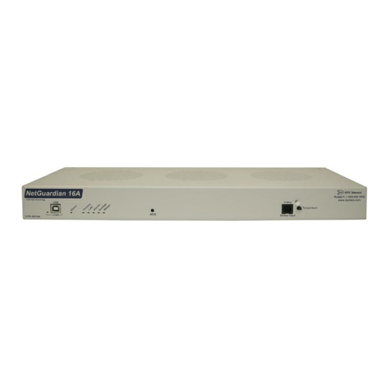
Page 20: Netguardian Front Panel
NetGuardian Front Panel NetGuardian 16A front panel USB Craft Port Use the front-panel USB craft port to connect the NetGuardian to a PC for onsite unit configuration. To connect via the USB craft port, use a standard A-B USB cable. This is the same type of cable used for many USB printers. -
Page 21: Quick Start: How To Connect To The Netguardian
Alternative option: You can skip the TTY interface by using a LAN crossover cable directly from your PC to the NetGuardian 16A and access its Web Browser. See the "...via LAN" section of this chapter..via USB Craft Port (using TTY Interface) The simplest way to connect to the NetGuardian is over a physical cable connection between your PC's USB port and the unit's USB craft port. - Page 22 Note: The following images display the setup process done in Windows XP. The following steps will occur the first time any DPS USB equipment is used on this PC. If you've used a different DPS USB device before and have installed the DPS USB drivers, then skip to Step 9. When you first connect the NetGuardian to your PC via USB, a "Found New Hardware"...
- Page 23 6. Click "Browse" 7. Select the "Driver" folder of your NetGuardian Resource Disc Disc (CD) and click "OK" The following message will confirm installation of a new "USB Communications Port" 8. Click "Finish" to close the Wizard. Now that the driver has been installed, a new COM port is being emulated on your PC. Before using hyperterminal, you must confirm the identity of that new COM port (COM1, COM2, COM3...) in the Windows Device Manager.
- Page 24 9. Right-click the "My Computer" icon on your desktop, then click "Manage" 10.Click "Device Manager" in the left pane.
- Page 25 11.Expand the "Ports (COM & LPT)" section in the right pane. Look for "USB Communications Port (COMx)". Note the number of the COM port ("COM3" in the example above). Now that you know which COM port to use, it's time to launch HyperTerminal (or other terminal software): 12.Click on the Start menu >...
- Page 26 • Stop bits: 1 PC and make sure you are using the cable provided. • Flow control: None Additional cables can be ordered from DPS Telecom. Once connected, you will see a blank, white HyperTerminal screen. Press Enter to activate the configuration menu.
- Page 27 Now you're ready to do the rest of your configuration via LAN. Plug the NetGuardian into your LAN and see the "Logging On to the NetGuardian" section to continue databasing using the Web Browser..via LAN Connection through Ethernet port To connect to the NetGuardian via LAN, all you need is the unit's IP address (Default IP address is 192.168.1.100).
-
Page 28: Tty Interface
TTY Interface The TTY interface is the NetGuardian's built-in interface for basic configuration. From the TTY interface, you can: · Edit the IPA, subnet, and gateway · Set DCP info for T/Mon polling · Configure primary port · Ping other devices on the network ·... -
Page 29: Configure Serial Port
Configure Serial Port Serial port configuration 1. To enter configuration setting for the Serial Port, login to the TTY interface and press C)onfig > pr(I) maryPort. 2. Press the hot keys to toggle through the following options. (* Indicates default settings:) NOTE: Default settings may not reflect the primary interface that shipped in the unit. -
Page 30: Set Dcp Parameters
Set DCP Parameters Setting DCP Parameters 1. Login to the TTY interface and press C)onfig > D)CP. 2. Set the DCP Address (Unit ID). 3. Set the DCP listening type (toggle through the options). Choose over serial, over LAN*, or disabled. ·... -
Page 31: Netguardian Web Browser
NetGuardian Web Browser The NetGuardian features a built-in Web Browser Interface that allows you to manage alarms and configure the unit through the Internet or your Intranet. You can quickly set up alarm point descriptions, view alarm status, issue controls, configure paging information, and more. -
Page 32: Changing The Default Password
9.1.1 Changing the Default Password The password can be configured from the Provisioning > User Profiles screen. The minimum password length is four characters; however, DPS recommends setting the minimum password length to at least five characters. Use the following steps to change the logon password: 1. -
Page 33: Netguardian - Quick Turn Up
NetGuardian - Quick Turn Up The next 2 sections of this manual will walk you through some of the most common tasks for using the NetGuardian. You will learn how to send email notifications, and send SNMP traps to your alarm master - all using the Web browser. - Page 34 4. At the Schedule screen, you'll select the exact days/times you want to receive email notifications. You can set 2 schedules per notification. For example, you may want to receive notifications at certain times during the week, and at different hours on the weekend. Use the check boxes to select the days of the week, and select the time from the drop down menus.
-
Page 35: How To Send Snmp Traps
10.2 How to Send SNMP Traps 1. Click on the SNMP button in the Provisioning menu. Enter the SNMP GET and SNMP SET community strings for your network, then click Save. The typical SNMP SET and GET community strings for network devices is "public". - Page 36 5. At the Schedule screen, you'll select the exact days/times you want to receive SNMP notifications. You can set 2 schedules per notification. For example, you may want to receive notifications at certain times during the week, and at different hours on the weekend. Use the check boxes to select the days of the week, and select the time from the drop down menus.
-
Page 37: Provisioning Menu Field Descriptions
Provisioning Menu Field Descriptions NetGuardian configuration is performed from the Provisioning menus, the menu options in green on the left-side of the web interface. The following pages provide a brief description of the options available in each menu. Saving Configuration Changes to the NetGuardian: At the bottom of each screen you access from the Provisioning Menu, you will see a Save button. -
Page 38: System
11.1 System From the Provisioning > System menu, you will configure and edit the global system, call, T/Mon and control settings for the NetGuardian. The Provisioning > System menu Global System Settings Name A name for this NetGuardian unit. {Optional field) Location The location of this NetGuardian unit. - Page 39 Configure access privileges for users in the User Profile screen Note: The first user profile in the User Profiles menu is the Administrator's Profile. Access rights for the administrator's profile are all enabled and may not be disabled, nor can the profile be deleted or suspended. This is a precaution to prevent a situation in which an access right is disabled for all users.
- Page 40 User Profile Password Enter a unique user password Note: All passwords are AES 128 encrypted. Confirm Password Re-enter the password. Access Rights Check all Enables all Access Rights Edit logon profiles Enables the user to add/modify user profiles and password information. Write Config (change Enables the user to change the unit config by accessing the Write feature in the unit configuration)
-
Page 41: Ethernet
11.3 Ethernet The Edit > Ethernet menu allows you to define and configure Ethernet settings. The Provisioning > Ethernet menu Ethernet Settings MAC Address Hardware address of the NetGuardian. (Not editable - For reference only.) Used only for web browsing. Example: If you don't want to remember this NetGuardian's IP address, you can type in a name is this field, such as NG16. -
Page 42: Radius
11.4 RADIUS RADIUS (Remote Authentication Dial In User Service) is an industry-standard way to manage logins to many different types of equipment in one central location. The NetGuardian connects to your central RADIUS server. Every time a device receives a login attempt (usually a username & password), it requests an authentication from the RADIUS server. -
Page 43: Serial Ports
11.5 Serial Ports The Provisioning > Serial Port menu allows you to change settings depending on the port type of your NetGuardian. From this menu, you can select a mode of operation and enable reach-through serial port functionality. The Provisioning > Serial Ports menu Location A reminder that your primary serial port is located on the back of the NetGuardian chassis. -
Page 44: Snmp
11.6 SNMP The Provisioning > SNMP menu allows you to define and configure the SNMP settings. SNMP Menu Global Settings Get Community Community name for SNMP requests. Set Community Community name for SNMP SET requests. This field defines how the NetGuardian unit may be accessed via SNMP. This can be set to the following: Read and Write ·... -
Page 45: 11.7.1 Notification Settings
11.7.1 Notification Settings Email Notification Fields Editing Email Notification Settings Email Notification SMTP Server IP or The IP address of your email server. Host Name Port Number The port used by your email server to receive emails, usually set to 25. Check this box to use SSL encryption. -
Page 46: 11.7.2 Schedule
SNMP Notification SNMP Trap Server IP The SNMP trap manager's IP address. The SNMP port (UDP port) set by the SNMP trap manager to receive Trap Port No. traps, usually set to 162. Trap Community Community name for SNMP TRAP requests. Trap Type Indicate whether you would like to send SNMP v1, v2c, or v3 traps. -
Page 47: Alarms
11.8 Alarms Discrete alarms are configured from the Provisioning > Alarms menu. Descriptions for the alarm points, polarity (normal or reversed) and notification type(s) are defined from this menu. You also have the option to use Basic or Advanced configuration methods, explained in this section. The Provisioning >... -
Page 48: Controls
11.9 Controls The NetGuardian's 2-18 control relays can be configured in the Provisioning > Controls menu. You can enter your own description for these relays and designate them to a notification device(s). The Provisioning > Controls screen Basic Controls Configuration ID number for the control relay. -
Page 49: Analogs
11.10 Analogs The NetGuardian can have up to 6 analog channels. The 5th and 6th channels are dedicated to monitoring the power input (channel is not used if build option was not selected). These channels support the entire range of power inputs that the NetGuardian can support. - Page 50 Basic Analog Configuration Analog ID number. Enab Check this box to enable the analog. Description User-definable description for the analog channel. Check which notification device(s), 1 through 8, you want to send alarm notifications Notification Devices for that alarm point. Rev.
-
Page 51: Sensors
11.11 Sensors The NetGuardian supports up to 32 daisy-chained D-Wire sensors via its D-Wire input. Sensors connected to the NetGuardian will appear on the NetGuardian's web interface. The background color of the ROM field informs the user of the sensor's configuration state. Also the NetGuardian's first D-Wire sensor used to monitor the internal temperature. - Page 52 Basic Sensor Configuration Sensor ID number. The ID number found on the sticker of the temperature sensor node. Your NetGuardian will automatically detect the sensor ID when you plug a sensor into the unit. The color of the sensor ID field will tell you the status of the connected sensor. Green - The sensor is connected and properly configured.
-
Page 53: Dscp
11.12 DSCP The NetGuardian supports DPS Server Client Protocol (DSCP) for communication with external DSCP devices (such as the Track Monitor). The Provisioning > DSCP menu allows you to configure settings for sync'd DSCP devices. Note: The Track Monitor DSCP device supports 2 alarm points and 6 analog channels. The 2 alarm points and analog channels 1 &... - Page 54 DSCP device is sync'd with the NetGuardian. Note: This field must be cleared before a new DSCP device can sync with the NetGuardian. The rate with which the Track Monitor will report sensor data to the NetGuardian. Note: The Track Monitor spends a majority of the time in 'sleep mode' to conserve Update Frequency power.
-
Page 55: Ping Targets
11.13 Ping Targets The Provisioning > Ping Targets menu allows you to configure the Description, IP Address, and Notification Devices for each of your 32 ping targets. The Provisioning > Ping Targets menu Provisioning Ping Targets ID number for the ping target. Enab Check this box to enable the ping target. -
Page 56: System Alarms
11.14 System Alarms See "Display Mapping" in the Reference Section for a complete description of system alarms. The Provisioning > System Alarms menu Editing System Alarms Pnt (Point) The system alarm point number Description Non-editable description for this System (housekeeping) Alarm. Silence Check this box to choose to silence this alarm. -
Page 57: Timers
and reset the speaker progression. BAU Mode Setup: 1. Check Enable BAU Mode in ProvisioningàBAU Globals 2. Set the ProvisioningàBAU GlobalsàSpeaker Sound Control ID to the Control Id that is connected to the external speaker. 3. For the Control Id chosen as the Speaker Sound Control ID, set the ProvisioningàControlsàDetailsàDerived Description to "_ORD1.1-N", where N is the max number of discrete alarms monitored/supported. -
Page 58: Date And Time
11.17 Date and Time The Provisioning > Date and Time menu Unit Time Date Set today's date. Time Set the current time. Automatic Time Adjustment (NTP) Enable NTP Check this box to enable Network Time Protocol. Enter the NTP server's IP address or host name, then click Sync. NTP Server Address or Host Name Example: us.pool.ntp.org. -
Page 59: Monitoring Via The Web Browser
Monitoring via the Web Browser 12.1 Alarms This selection provides the status of the base alarms by indicating if an alarm has been triggered. Under the State column, the status will appear in red if an alarm has been activated. The status will be displayed in green when the alarm condition is not present. - Page 60 View and operate control relays from the Monitor > Controls menu Control Relay Operation Disable Control Disable Control Confirmation pop-ups when operating controls. Confirmation ID number for the control relay. Description for the NetGuardian's control relay defined in the Provisioning > Controls Description menu.
-
Page 61: Analogs
12.3 Analogs The Monitor > Analogs screen provides a description of each analog channel, the current reading, the units being read, and alarm conditions (major under, minor under, major over, minor over) according to your temperature settings. If configured under Provisioning > Analogs, your analog values will be displayed as a graphical gauge. Selecting Table View will display a non-graphical interface of your values. -
Page 62: Sensors
12.4 Sensors This selection provides the status of the system's analog channels by indicating if an alarm has been triggered. The Monitor > Sensors screen provides a description of each analog channel, the current reading, the units being read, and alarm conditions (major under, minor under, major over, minor over) according to your temperature settings. If configured under Provisioning >... -
Page 63: Dscp
12.5 DSCP The Monitor > DSCP screen provides a description of each DSCP device alarm point state and each DSCP device analog channel, the current reading, the units being read, and alarm conditions (major under, minor under, major over, minor over) according to your analog settings. Click on DSCP in the Monitor menu to view the current DSCP device statuses. -
Page 64: System Alarms
12.7 System Alarms System alarms are not-editable, housekeeping alarms that are programmed into NetGuardian. The Monitor > System Alarms screen provides the status of the system alarms by indicating if an alarm has been triggered. Under the State column, the status will appear in red if an alarm has been activated. The status will be displayed in green when the alarm condition is not present. - Page 65 Provision the Channels, Group Interval, Group Function and more - all from the Graph Parameters section of the web browser interface.
- Page 66 Your graph will appear on the next screen. This graph is Adobe Flash-based and allows you to mouse over the lines to quickly view measurements (date, time, and value) within their context of the overall graphing trend. Below the graph is a full textual list of all indexed points with their dates and values. Specify your parameter values and build an interactive graph based on the alarm point history.
-
Page 67: Device Access Descriptions
Device Access Descriptions The Device Access options, listed in pink on the left side of the web interface, provide options for generating reports, updating the NetGuardian's firmware, and rebooting the unit. Click any of the options under Device Access to perform the desired action. -
Page 68: Firmware Upgrade
Firmware Upgrade To access the Firmware Load screen, click on the Provisioning > System menu. At the bottom of this screen, click the Restore Configuration link located in the System Controls section. To upload firmware, click on Upload on the top right corner of the web interface At the Firmware Load screen, simply browse for the firmware update you've downloaded from www.dpstele.com and click Load. -
Page 69: Reference Section
Reference Section 15.1 Front and Back Panel LEDs Status Description Blinking Green NetGuardian application running tatus Blinking Red Boot Loader is running Wireless Flashing Green Data transmit to wireless module Flashing Red Data received from wireless module Blinking Green LAN activity Alarms Flashing Red New alarm... -
Page 70: Display Mapping
15.2 Display Mapping Description Port Address Point Discrete Alarms 1-20 Control Relays 33-40 Reserved 41-43 Display 1 Door Violation Reserved 45-53 Stay-open Door Mode Active Reserved 55-64 Ping Targets 1-16 System Alarms 33-45 System Alarms 55-64 Display 2 DSCP Sensor Pow er Fault DSCP Sensor Pow er Low DSCP Unused 48-53... - Page 71 Analog 9 Polarity Analog 9 Value* 17-32 Analog 10 Minor Under, Minor Over 33, 34 Analog 10 Major Under, Major Over 35, 36 Analog 10 Range 41-43 Analog 10 Polarity Analog 10 Value* 49-64 *Note: "Analog Value*" must be multiplied by the appropriate VBIT from table 14.2 in order to create a displayable Value*.
- Page 72 Display Description Port Address Point Analog 11 Minor Under, Minor Over 1, 2 Analog 11 Major Under, Major Over 3, 4 Analog 11 Range 9-11 Analog 11 Polarity Analog 11 Value* 17-32 Display 8 Analog 12 Minor Under, Minor Over 33, 34 Analog 12 Major Under, Major Over 35, 36...
- Page 73 Display Description Port Address Point Digital Temp Sensor 3 Minor Under, Minor Over 1, 2 Digital Temp Sensor 3 Major Under, Major Over 3, 4 Digital Temp Sensor 3 - Sensor not Detected Digital Temp Sensor 3 Range 9-11 Digital Temp Sensor 3 Polarity Digital Temp Sensor 3 Value* 17-32 Display 13...
- Page 74 Display Description Port Address Point Digital Temp Sensor 11 Minor Under, Minor Over 1, 2 Digital Temp Sensor 11 Major Under, Major Over 3, 4 Digital Temp Sensor 11 - Sensor not Detected Digital Temp Sensor 11 Range 9-11 Digital Temp Sensor 11 Polarity Digital Temp Sensor 11 Value* 17-32 Display 17...
- Page 75 Display Description Port Address Point Digital Temp Sensor 19 Minor Under, Minor Over 1, 2 Digital Temp Sensor 19 Major Under, Major Over 3, 4 Digital Temp Sensor 19 - Sensor not Detected Digital Temp Sensor 19 Range 9-11 Digital Temp Sensor 19 Polarity Digital Temp Sensor 19 Value* 17-32 Display 21...
- Page 76 Display Description Port Address Point Display 25 Digital T emp Sensor 27 Minor Under, Minor Over 1, 2 Digital T emp Sensor 27 Major Under, Major Over 3, 4 Digital T emp Sensor 27 - Sensor not Detected Digital T emp Sensor 27 Range 9-11 Digital T emp Sensor 27 Polarity Digital T emp Sensor 27 Value*...
-
Page 77: System Alarms Display Map
Call DPS Tech Support - (559) - 454-1600 See Section "Quick Start: How to Connect to the NetGuardian 16A via Craft Port." If not using the IP Address Not Set The IP Address is not set NetGuardian over LAN, set the IP address to 255.255.255.255... -
Page 78: Snmp Manager Functions
15.4 SNMP Manager Functions The SNMP Manager allows the user to view alarm status, set date/time, issue controls, and perform a resync. The display and tables below outline the MIB object identifiers. Table 14.3 begins with dpsRTU; however, the MIB object identifier tree has several levels above it. The full English name is as follows: root.iso.org.dod.internet.private.enterprises.dps-Inc.dpsAlarmControl.dpsRTU. -
Page 79: Snmp Granular Trap Packets
SNMP Granular Trap Packets The tables below provide a list of the information contained in the SNMP Trap packets sent by the NetGuardian 16A SNMP Trap managers can use one of two methods to get alarm information: 1.Granular traps (not necessary to define point descriptions for the NetGuardian) OR 2.The SNMP manager reads the description from the Trap. -
Page 80: Frequently Asked Questions
NetGuardian 16A. Ordering TTL points for your NetGuardian 16A does not add to the cost of the unit. What you can do with the configuration software is change any alarm point from "Normal" to "Reversed" operation. Switching... -
Page 81: Snmp Faqs
A. A point map is a single MIB leaf that presents the current status of a 64-alarm-point display in an ASCII-readable form, where a "." represents a clear and an "x" represents an alarm. Q. The NetGuardian 16A manual talks about control relay outputs. How do I control these from my SNMP manager? A. - Page 82 2. Make sure all alarm points are configured to send SNMP traps. 3. Make sure the NetGuardian 16A and the SNMP manager are both on the network. Use the unit's ping command to ping the SNMP manager.
-
Page 83: Technical Support
Please have your user manual and hardware serial number ready. 3. Have access to troubled equipment. Please be at or near your equipment when you call DPS Telecom Technical Support. This will help us solve your problem more efficiently. -
Page 84: End User License Agreement
DPS Telecom which arise out of or are related to the non-fulfillment of any covenant or obligation of End User in connection with this Agreement. - Page 89 Warranty DPS Telecom warrants, to the original purchaser only, that its products a) substantially conform to DPS' published specifications and b) are substantially free from defects in material and workmanship. This warranty expires two years from the date of product delivery with respect to hardware and ninety days from the date of product delivery with respect to software.
- Page 90 Free Tech Support is Only a Click Away Need help with your alarm monitoring? DPS Information Services are ready to serve you … in your email or over the Web! www.DpsTele.com Free Tech Support in Your Email: The Protocol Alarm Monitoring Ezine The Protocol Alarm Monitoring Ezine is your free email tech support alert, delivered directly to your in-box every two weeks.
Need help?
Do you have a question about the NetGuardian 16A and is the answer not in the manual?
Questions and answers