Kessel Ecolift SPZ 1000 Instructions For Installation, Operation And Maintenance
Hide thumbs
Also See for Ecolift SPZ 1000:
- Installation and operating instructions manual (104 pages)
Table of Contents
Advertisement
Available languages
Available languages
Quick Links
ANLEITUNG FÜR EINBAU, BEDIENUNG UND WARTUNG
KESSEL Ecolift
LGA
Bauart
Bauart
Landesgewerbeamt Bayern
geprüft
geprüft
und überwacht
und überwacht
LGA
Bauart
Bauart
Landesgewerbeamt Bayern
geprüft
geprüft
und überwacht
und überwacht
Installation
der Anlage wurde durchgeführt von Ihrem Fachbetrieb:
Name/Unterschrift
Stand 2019/12
Ecolift
Einbau in die
Bodenplatte
Ecolift
freiliegend
Inbetriebnahme
Datum
Einweisung
Ort
Stempel Fachbetrieb
GB
NL Pagina 105
PL
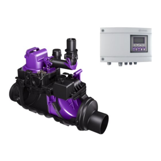
Produktvorteile
Für fäkalienhaltiges und
fäkalienfreies Abwasser
Funktionalität von
Rückstauverschluss und
Hebeanlage
Sicherheit einer Hebeanlage
Steckerfertiges Schaltgerät mit Display
und Selbstdiagnosesystem (SDS) inkl.
integrierter Batteriepufferung
Motorische Verriegelung der
Rückstauklappe
Integrierte Ablauffunktion zur
Oberflächenentwässerung
D
Seite 1
Page 27
F
Page 54
I
Pagina 79
Strona 131
85101 Lenting
Z-53.2-487
Sach-Nr. 010-844
Advertisement
Chapters
Table of Contents

Subscribe to Our Youtube Channel
Related Manuals for Kessel Ecolift SPZ 1000


Summary of Contents for Kessel Ecolift SPZ 1000
- Page 1 ANLEITUNG FÜR EINBAU, BEDIENUNG UND WARTUNG Seite 1 KESSEL Ecolift Page 27 Page 54 Pagina 79 NL Pagina 105 Strona 131 Produktvorteile Für fäkalienhaltiges und fäkalienfreies Abwasser Funktionalität von Rückstauverschluss und Hebeanlage Sicherheit einer Hebeanlage Ecolift Steckerfertiges Schaltgerät mit Display Einbau in die und Selbstdiagnosesystem (SDS) inkl.
-
Page 2: Table Of Contents
Allgemeine Hinweise zu dieser Anleitung Produktbeschreibung, allgemein ........................4 Allgemeine Hinweise zu dieser Betriebs- und Wartungsanleitung ............5 Funktionsprinzip ................................5 1.3.1 Funktionsprinzip Ecolift (Einbau in die Bodenplatte) ...................5 1.3.2 Funktionsprinzip Ecolift (freiliegend) .........................6 Typenschild ..................................6 Lieferumfang ................................7 1.5.1 Variante Ecolift - Einbau in die Bodenplatte ....................7 1.5.2 Variante Ecolift freiliegend .............................7 Sicherheit... - Page 3 3.15 Zulaufdeckel montieren ............................20 Funktionsprüfung/ Inbetriebnahme Wartung Allgemeine Hinweise für die Wartung .......................22 Wartungsintervalle ..............................22 Technische Daten Pumpen ..................................23 Schaltgerät Ecolift ..............................23 Förderstrom .................................24 DOP/Leistungserklärung 12/2019 3 / 156...
-
Page 4: Allgemeine Hinweise Zu Dieser Anleitung
Informationen zur Abwicklung und Bestellung finden Sie unter: http://www.kessel.de/service/kundenservice.html Produktbeschreibung, allgemein Die KESSEL Rückstaupumpanlage Ecolift (im folgenden Rückstaupumpanlage genannt) ist für das Abpumpen von fäkalienfreiem und fäkalienhaltigem Abwasser vorgesehen. In den Grundkörper sind die Baugruppen für die Pumpen, den Drucksensor und die motorisch angetriebene Rückstauklappe eingebaut. -
Page 5: Allgemeine Hinweise Zu Dieser Betriebs- Und Wartungsanleitung
Allgemeine Hinweise zu dieser Anleitung Allgemeine Hinweise zu dieser Betriebs- und Wartungsanleitung Diese Betriebs- und Wartungsanleitung ist nur in Verbindung mit der Betriebs- und Montageanleitung des Ecolift Schaltgeräts (Sach-Nr. 016-004) vollständig. Verwendete Symbole und Legenden <1> Hinweis im Text auf eine Legendennummer in einer Abbildung Bezug auf eine Abbildung •... -
Page 6: Funktionsprinzip Ecolift (Freiliegend)
Allgemeine Hinweise zu dieser Anleitung 1.3.2 Funktionsprinzip Ecolift (freiliegend) Abb. [2] Druckleitung Rückstauebene Typenschild Informationen auf dem Typenschild Ecolift xxxxx Bezeichnung der Anlage U = xxxV xxHz I = x,xA P1 = x,xkW Q = xxm³/h H = xxm Artikelnummer S3 xx% ED IP xx (3mWS /48h) Ser.Nr. -
Page 7: Lieferumfang
Allgemeine Hinweise zu dieser Anleitung Lieferumfang Anlage bzw. alle Lieferkomponenten auf Vollständigkeit und evtl. Mängel überprüfen. 1.5.1 Variante Ecolift - Einbau in die Bodenplatte Grundkörper Aufsatzstück, mit Zulaufdeckel Verlängerungsstück (optional max. 2 Stück) Pumpeneinheit Motorische Klappeneinheit Dichtung Kabeldurchführung Durchführung Druckleitung Zulauf-Seite Ablauf-Seite Elektropack (E-Pack) -
Page 8: Sicherheit
Sicherheit Sicherheit Bestimmungsgemäße Verwendung Die Rückstaupumpanlage dient als Entwässerungsanlange für fäkalienhaltiges und –freies, häusliches und gewerbliches Abwasser. Personalauswahl und -qualifikation Personen, die die Rückstaupumpanlage montieren, müssen – mindestens 18 Jahre alt sein. – für die jeweiligen Tätigkeiten ausreichend geschult und qualifiziert sein. –... -
Page 9: Gefahr Für Die Gesundheit
Sicherheit 2.4.4 Gefahr für die Gesundheit Die Rückstaupumpanlage fördert fäkalienhaltiges Abwasser, welches gesundheitsgefährdende Stoffe enthalten kann. Sicherstellen, dass kein direkter Kontakt zwischen dem Abwasser oder davon verschmutzten Anlagenteilen mit Augen, Mund oder Haut stattfindet. Bei einem direkten Kontakt die betroffene Körperstelle sofort gründlich reinigen und ggf. -
Page 10: Montage
Montage Montage Baugruppen und Funktionsmerkmale, Lieferumfang Montage in einer freiligenden Abwasserleitung Abb. [6] Pumpe Alarmsonde Rückstauklappe Motor Rückstausonde Anschluss Druckleitung 10 / 156 12/2019... - Page 11 Montage Einbau in die Bodenplatte Abb. [7] Geruchsverschluss für Bodenablauf Pumpe Alarmsonde Rückstauklappe Rückstausonde Motor Anschluss Druckleitung 12/2019 11 / 156...
-
Page 12: Allgemeines Zur Montage
Montage Allgemeines zur Montage Die Rückstaupumpanlage wird entsprechend den auf einer Baustelle üblichen Bauabschnitten zu unterschiedlichen Zeitpunkten montiert und in Betrieb genommen. Einbauvorschlag „Schwarze Wanne“ Schematische BWS* Darstellung Abb. [8] 1 Ecolift 2 Dichtungsset Art.-Nr. 83 073: Verlängerungsstück mit Flansch und Gegenflansch (für den Anschluss an eine bauseitige Dichtbahn) 3 Verlängerungsstück Art.-Nr. -
Page 13: Einbauvorschlag „Weiße Wanne
Montage Einbauvorschlag „Weiße Wanne“ Schematische Darstellung BWS* Abb. [9] 1 Ecolift 2 Verlängerungsset mit mittigem Flansch für den Einbau in WU-Beton, Art.-Nrt. 83 075 a Fliesen f Dämmung b Abdichtung g Sauberkeitsschicht c Estrich h Schaltgerät d Betonboden i Druckleitung e Dämmung BWS* Bemessungswasserstand Vorbereitungen zum Einbau... -
Page 14: Grundkörper Montieren
Montage Die Kabellänge der Elektrokomponenten beträgt 5 Meter (Verlängerungen optional erhältlich). Damit die Pumpe bei Wartungsarbeiten vollständig aus dem Grundkörper herausgehoben werden kann, muss sich eine ausreichende Kabellänge des Pumpen-Anschlusskabels im Grundkörper befinden. Das Kabelleerrohr dient zur Entlüftung des Raumes oberhalb der Pumpe. Es darf deshalb nicht luftdicht verschlossen werden. -
Page 15: Grundkörper Waagerecht Ausrichten
Montage Einbau in freiliegende Abwasserleitung Einbau in die Bodenplatte Abb. [12] Abb. [13] Unbedingt auf die Fließrichtung achten und Dichtung einlegen. (Siehe Pfeil <77> Abb. [12] bzw. Abb. [13]). Grundkörper waagerecht ausrichten Abb. [14] 12/2019 15 / 156... -
Page 16: Einbau In Die Bodenplatte (Schwarze Wanne)
Montage Einbau in die Bodenplatte (schwarze Wanne) Bauseitige Dichtungsbahn <68> zwischen Pressdichtungsflansch <13> und Gegenflansch <47> einklemmen und mit den Schrauben <48> verschrauben. Abb. [15] Einbau in die Bodenplatte (weiße Wanne) Dichtung <37> in Grundkörper <1> einlegen und auf Sitz der Dichtung achten. -
Page 17: Entlüftung Sicherstellen
Montage 3.10 Entlüftung sicherstellen Bei freiliegendem Einbau sicherstellen, dass das vormontierte Entlüftungsventil inkl. Aktivkohlefilter <11> fest angeschraubt ist. Bei Einsatz im Schachtverbau Entlüftungsventil demontieren und Entlüftungsleitung über die Rückstauebene führen, siehe nachfolgendes Kapitel. 3.10.1 Entlüftungsleitung anschließen Um die Funktion in allen Einsatzfällen im Schachtverbau im Falle einer Überflutung zu gewährleisten, ist die Entlüftungsleitung mind. -
Page 18: Anschluss Druckleitung Vorbereiten
Montage 3.11 Anschluss Druckleitung vorbereiten - Verschlussstopfen <21> am Grundkörper <1> entfernen. - Dichtung <24> einlegen. - Anschlussstück <22> vom Inneren des Grundkörpers am Zwischenstück <1> montieren und die Mutter <23> von der Außenseite mit ca 10 Nm anziehen. - Bauseitige Druckleitung am Anschlussstück anschließen. Abb. -
Page 19: Kabelleerrohr Montieren
(DN50) an den Grundkörper heranführen und montieren. Für Richtungsänderungen max. 45° Bögen verwenden. Sollte das Kabelleerrohr im Aufsatzstück installiert werden, muss dieses mit der KESSEL Sägeglocke Art.-Nr. 500 101 oder einer handelsüblichen Sägeglocke Ø 60 mm und der Rohrdurchführungsdichtung Art.-Nr. 850 114 ausgeführt werden. -
Page 20: Aufsatzstück Montieren
Montage 3.14 Aufsatzstück montieren Je nach Einbautiefe ist das Aufsatzstück (Einstecktiefe des Aufsatzstückes <3>) ggf. abzulängen bzw. mit Aussparungen <67> für die Leitungsverbindungen, die seitlich in den Grundkörper <1> hineingeführt werden, zu versehen. Das Aufsatzstück <3> darf mit maximal 2 Verlängerungsstücken verlängert werden, damit zu Wartungszwecken noch bis zum Grundkörper hinunter gegriffen werden kann. -
Page 21: Funktionsprüfung/ Inbetriebnahme
Funktionsprüfung/ Inbetriebnahme Funktionsprüfung/ Inbetriebnahme Vor der Inbetriebnahme muss eine Funktionsprüfung aller elektrischen Komponenten durchgeführt werden. Funktionsprüfung Rückstau 1. Prüfen, ob alle elektrischen Anschlüsse ordnungsgemäß ausgeführt wurden, Stromverbindung herstellen. 2. Rückstausonde demontieren und in Wasserglas eintauchen. 3. Prüfen, ob Rückstauklappe zufährt. (Motorengeräusch, Hebel legt sich selbsttätig um). 4. -
Page 22: Wartung
Wartung Wartung Vor einem Öffnen von Gehäuseabdeckungen, Steckern und Kabeln (auch an den potentialfreien Kontakten), sind diese spannungsfrei zu machen. Arbeiten an elektrischen Bauteilen dürfen nur von Fachpersonal (siehe 2.2) durchgeführt werden. Allgemeine Hinweise für die Wartung Bei Wartungsarbeiten darf nicht auf elektrische Komponenten, Leitungsverbindungen oder Kabel gestiegen werden. -
Page 23: Technische Daten
Technische Daten Technische Daten Pumpen Pumpe 1000 Gewicht [kg]* 10,5 Leistung P1 [kW] Leistung P2 [kW] Drehzahl [U/min] 2800 Betriebsspannung [V] 50 Hz Nennstrom [A] Förderleistung max. [m³/h] Förderhöhe max. [m] Förderguttemperatur max. [°C] Schutzart IP 68 (bei max. 3 mWS und max. 48 h) Schutzklasse Motorschutz integriert... -
Page 24: Förderstrom
Technische Daten Förderstrom Werte für SPZ 1000 mit Schneidrad Max. Förderm Q (m 10,0 10,9 Max. Förderm Q (l/sec.) Förderhöhe H (mWS) H [ m ] Q [ m /h ] Abb. [23] 24 / 156 12/2019... -
Page 25: Dop/Leistungserklärung
DOP/Leistungserklärung DOP/Leistungserklärung 12/2019 25 / 156... - Page 26 DOP/Leistungserklärung 26 / 156 12/2019...
- Page 27 INSTRUCTIONS FOR INSTALLATION, OPERATION AND MAINTE- NANCE KESSEL Ecolift Product advantages For wastewater with and without sewage Functionality of backwater valve and lifting station Safety of a lifting station Plug & play control unit with display and self-diagnosis system (SDS) incl.
- Page 28 General information about this manual Product description, general ..........................30 General instructions on using these operating and maintenance instructions .........31 How it works ................................31 1.3.1 How the Ecolift for installation in concrete floor slabs works ..............31 1.3.2 How the Ecolift for exposed installation works ....................32 Type plate ..................................32 Scope of delivery ...............................33 1.5.1...
- Page 29 3.15 Installing the inflow cover ............................46 Functional check/ commissioning Maintenance General maintenance information ........................48 Maintenance intervals .............................48 Technical data Pumps ....................................49 Ecolift control unit ..............................49 Pumping flow ................................50 DoP/ Declaration of Performance 12/2019 29 / 156...
-
Page 30: General Information About This Manual
Product description, general The KESSEL backwater pumping station Ecolift (referred to as the backwater pumping station from here onwards) has been designed for pumping off wastewater with and without sewage. The assemblies for the pumps, pressure sensor and motor-driven backwater flap are installed in the drain body. -
Page 31: General Instructions On Using These Operating And Maintenance Instructions
General information about this manual General instructions on using these operating and maintenance instructions These operating and maintenance instructions are only complete in combination with the operating and maintenance instructions of the Ecolift control unit (part no. 016-004). Symbols and legends used <1>... -
Page 32: How The Ecolift For Exposed Installation Works
General information about this manual 1.3.2 How the Ecolift for exposed installation works Fig. [2] Pressure pipe Backwater level Type plate Information on the typeplate Ecolift xxxxx Name of the system U = xxxV xxHz I = x,xA P1 = x,xkW Q = xxm³/h H = xxm Article number... -
Page 33: Scope Of Delivery
General information about this manual Scope of delivery Check the system and all components supplied for completeness and for any faults. 1.5.1 Variant Ecolift for installation in concrete floor slab Drain body Upper section, with inflow cover Extension section (optional, max. 2 units) Pump unit Motor-driven flap unit Seal... -
Page 34: Safety
Safety Safety Correct use The backwater pumping station serves as a draining system for wastewater with and without sewage, domestic and industrial wastewater. Staff selection and qualification Persons who install the backwater pumping station must – be at least 18 years old. –... -
Page 35: Health Risks
Safety 2.4.4 Health risks The backwater pumping station pumps wastewater with sewage which can contain hazardous substances. Make sure eyes, mouth or skin do not come into direct contact with the wastewater or parts of the system soiled by it. In the case of direct contact, the part of the body affected must be washed thoroughly immediately and disinfected if necessary. -
Page 36: Installation
Installation Installation Assemblies and functional characteristics, scope of delivery Installation in an exposed drainage pipe Fig. [6] pump alarm probe backwater flap motor backwater probe connection pressure pipe 36 / 156 12/2019... - Page 37 Installation Installation in the concrete slab Fig. [7] odour trap for floor drain pump alarm probe backwater flap backwater probe motor connection pressure pipe 12/2019 37 / 156...
-
Page 38: General Points Related To Installation
Installation General points related to installation The backwater pumping station is installed and put into operation at different times according to the usual construction phases on a building site. Installation suggestion “black tub” Schematic illustration BWS* Fig. [8] 1 Ecolift 2 Sealing gasket set art. -
Page 39: Installation Suggestion "White Tub
Installation Installation suggestion “white tub” Schematic illustation BWS* Fig. [9] 1 Ecolift 2 Extension set with central flange for installation in impermeable concrete, art. # 83 075 a Tiles f Insulation b Seal g Clean layer c Screed h Control unit d Concrete floor i Pressure pipe e Insulation... -
Page 40: Preparing For Installation
Installation Preparing for installation For smooth installation and operation, please heed the following: - Make sure there is a sufficient gap to the wall or other objects for maintenance work to be carried out. - Maintain a stilling section before and after the Ecolift (min. 1 m). - Execute the pressure pipe in accordance with DIN EN 12056 (with backwater loop via the locally specified backwater level and connect directly to an extended (min. -
Page 41: Aligning The Drain Body Horizontally
Installation Installation in an exposed drainage pipe Installation in the concrete slab Fig. [12] Fig. [13] Always pay attention to the direction of flow and insert sealing gasket (see arrow <77> Fig. [12] and Fig. [13]) Aligning the drain body horizontally Fig. -
Page 42: Installation In The Concrete Slab (Black Tub)
Installation Installation in the concrete slab (black tub) Clamp the on-site sealing sheet <68> between the pressure sealing flange <13> and the counterflange <47> and screw together using the screws <48>. Fig. [15] Installation in the concrete slab (white tub) Insert the sealing gasket <37>... -
Page 43: Ensure Ventilation
Installation 3.10 Ensure ventilation With exposed installation, make sure that the pre-assembled ventilation valve incl. activated carbon filter <11> is screwed tightly. For use within a chamber, dismantle the ventilation valve and route the venting pipe via the backwater level, see the section below. 3.10.1 Connecting the venting pipe In order to ensure the function of the system in chamber installation in case of flooding, the venting pipe is to be laid at least 10 cm above... -
Page 44: Preparing The Connection Of The Pressure Pipe
Installation 3.11 Preparing the connection of the pressure pipe - Remove the sealing plug <21> on the drain body <1>. - Insert sealing gasket <24>. - Fit the connecting piece <22> from the inside of the drain body on the extension section <1> and tighten the nut <23> from the outside using approx. -
Page 45: Installing The Cable Conduit
- For changes of direction use max. 45° bends. If the cable conduit has to be installed in the upper section, drill a hole with the KESSEL hole saw (article number 500 101) or a standard Ø 60 mm hole saw and put in the pipe sealing gasket (article number 850 114). -
Page 46: Installing The Upper Section
Installation 3.14 Installing the upper section Depending on installation depth, the upper section (insertion depth of the upper section <3>) must be cut to length or given recesses <67> for the pipe connections which are routed into the drain body <1>... -
Page 47: Functional Check/ Commissioning
Functional check/ commissioning Functional check/ commissioning Before commissioning, a functional check must be carried out on all electrical components. Functional check backwater 1. Check whether all electrical connections have been executed correctly, establish power connection. 2. Remove backwater probe and submerse it in a water glass. 3. -
Page 48: Maintenance
Maintenance Maintenance Before housing covers, plugs and cables (including those on potential-free contacts) are opened they must be switched voltage-free. Work on electrical components may only be carried out by specialist staff (see 2.2). General maintenance information No climbing on electrical components, pipe connections or cables during maintenance work. Risk caused by toxic and hazardous vapours, gases and substances (e. -
Page 49: Technical Data
Technical data Technical data Pumps Pump 1000 Weight [kg]* 10.5 Capacity P1 [kW] Capacity P2 [kW] Speed [rpm] 2800 Operating voltage [V] 50 Hz Nominal current [A] Max. pumping capacity [m³/h] Max. pumping height [m] Max. temperature of material to be conveyed [°C] Protective rating IP 68 (with max. -
Page 50: Pumping Flow
Technical data Pumping flow Values for SPZ 1000 with macerator Werte für SPZ 1000 mit Schneidrad Max. pumping capacity Max. Förderm Q (m 10,0 10,9 Max. pumping capacity Max. Förderm Q (l/sec.) Max. pumping height Förderhöhe H (mWS) H [ m ] Q [ m /h ] Fig. -
Page 51: Dop/ Declaration Of Performance
DoP/ Declaration of Performance DoP/ Declaration of Performance 12/2019 51 / 156... - Page 52 DoP/ Declaration of Performance 52 / 156 12/2019...
- Page 53 INSTRUCTIONS DE MONTAGE, D’UTILISATION ET DE MAINTE- NANCE KESSEL Ecolift Avantages du produit Pour eaux grises et eaux-vannes Fonctionnalité du clapet anti-retour et du poste de revelage Sécurité sans poste de relevage Gestionnaire « prêt à brancher » avec écran et système d‘autodiagnostic (SDS) Ecolift avec piles de sauvegarde intégrées...
- Page 54 Conseils d’ordre général concernant les instructions Description générale du produit .........................56 Informations d‘ordre général concernant ces instructions d‘utilisation et de maintenance ..57 Principe de fonctionnement ..........................57 1.3.1 Principe de fonctionnement de la variante Ecolift (pose dans la dalle de fondation ) ....57 1.3.2 Principe de fonctionnement de la variante Ecolift à...
- Page 55 3.15 Montage du couvercle d‘entrée ...........................72 Contrôle fonctionnel / mise en service Maintenance Conseils de maintenance d‘ordre général ......................74 Intervalles de maintenance ...........................74 Caractéristiques techniques Pompes ..................................75 Gestionnaire Ecolift ..............................75 Débit de refoulement ...............................76 DoP/ Déclaration de performance 12/2019 55 / 156...
-
Page 56: Conseils D'ordre Général Concernant Les Instructions
En qualité de producteur de pointe de produits novateurs dans le domaine de la technique d’assainissement, KESSEL propose des réponses systématiques globales et un service orienté aux besoins de la clientèle. Nous misons simultanément sur les normes de qualité les plus élevées et une durabilité conséquente – non seulement lors de la fabrication de nos produits, mais également pour leur utilisation à... -
Page 57: Informations D'ordre Général Concernant Ces Instructions D'utilisation Et De Maintenance
Conseils d’ o rdre général concernant les instructions Informations d‘ordre général concernant ces instructions d‘utilisation et de maintenance Ces instructions d‘utilisation et de maintenance ne sont complètes qu‘en combinaison avec les instructions d‘utilisation et de montage du gestionnaire Ecolift (Réf. n° 016-004). Pictogrammes et légendes utilisés <1>... -
Page 58: Principe De Fonctionnement De La Variante Ecolift À Installer Hors Sol
Conseils d’ o rdre général concernant les instructions 1.3.2 Principe de fonctionnement de la variante Ecolift à installer hors sol Fig. [2] Conduite de refoulement Niveau des plus hautes eaux Plaque signalétique Information sur la plaque signalétique Ecolift xxxxx Désignation du poste U = xxxV xxHz I = x,xA P1 = x,xkW... -
Page 59: Fournitures
Conseils d’ o rdre général concernant les instructions Fournitures Contrôler le poste et/ou tous les composants livrés quant à l‘intégralité et la présence éventuelle de défauts. 1.5.1 Variante Ecolift (pose dans la dalle de fondation ) Corps de base Rehausse, avec couvercle d‘entrée Pièce de rallonge (en option, au plus 2 pièces) Unité... -
Page 60: Sécurité
Sécurité Sécurité Utilisation conforme à l‘usage prévu Le clapet anti-retour avec pompe sert de système d‘assainissement des eaux-vannes, eaux grises et eaux domestiques et industrielles. Sélection et qualification du personnel Les personnes affectées au montage du clapet anti-retour avec pompe doivent –... -
Page 61: Risque Pour La Santé
Sécurité 2.4.4 Risque pour la santé Le clapet anti-retour avec pompe refoule des eaux-vannes susceptibles de contenir des substances nuisibles à la santé. Veiller à exclure tout risque d‘un contact direct entre les eaux usées ou les éléments souillés du poste avec les yeux, la bouche ou la peau. -
Page 62: Montage
Montage Montage Sous-groupes et éléments fonctionnels, détail de livraison Montage dans une conduite d’eau usée hors sol Fig. [6] Pompe Sonde d’alarme Clapet anti-retour Moteur Sonde de reflux Raccord de la conduite de refoulement 62 / 156 12/2019... - Page 63 Montage Pose dans la dalle de fondation Fig. [7] Dispositif anti-odeur pour siphon de sol Pompe Sonde d’alarme Clapet anti-retour Sonde de reflux Moteur Raccord de la conduite de refoulement 12/2019 63 / 156...
-
Page 64: Conseils De Montage D'ordre Général
Montage Conseils de montage d‘ordre général La pose, le montage et la mise en service du clapet anti-retour avec pompe sont effectués le moment donné suivant les tranches de travaux à effectuer habituellement sur le chantier. Suggestion de montage «cuve noire» Représentation BWS* schématique... -
Page 65: Suggestion De Montage " Cuve Blanche
Montage Suggestion de montage « cuve blanche » Représentation BWS* schématique Fig. [9] 1 Ecolift 2 Kit de rallonge avec bride médiane de pose dans du béton étanche, Réf. n° 83075 a Carrelage f Isolation b Étanchéité g Couche de propreté c Chape h Gestionnaire d Dalle de béton i Conduite de refoulement... -
Page 66: Montage Du Corps De Base
Montage longueur suffisante des câbles de raccordement de la pompe dans le corps de base afin qu‘il soit possible d‘extraire la pompe complètement du corps de base lors des interventions de maintenance. Le conduit de câbles sert à la ventilation de l‘espace au-dessus de la pompe. Sa fermeture n‘est donc pas hermétique à l‘air. -
Page 67: Positionnement Horizontal Du Corps De Base
Montage Pose dans une canalisation d‘eau usée hors sol Pose dans la dalle de fondation Fig. [12] Fig. [13] Veiller impérativement au sens du flux correct et insérer le joint d‘étanchéité. (voir la flèche <77> Fig. [12] ou Fig. [13]). Positionnement horizontal du corps de base Fig. -
Page 68: Pose Dans La Dalle De Fondation (Cuve Noire)
Montage Pose dans la dalle de fondation (cuve noire) Serrer la bande d‘étanchéité à prévoir sur site <68> entre la bride de compression <13> et la contre-bride <47> et relier par des vis <48>. Fig. [15] Pose dans la dalle de fondation (cuve blanche) Poser le joint d‘étanchéité... -
Page 69: Assurer La Ventilation
Montage 3.10 Assurer la ventilation En ce de pose hors sol, s’assurer que la vanne de ventilation prémontée avec filtre à charbon actif <11> est fermement vissée. En cas de pose dans le regard, démonter la vanne de ventilation et guider la conduite de ventilation par-dessus le niveau des plus hautes eaux, voir le point ci-après. -
Page 70: Préparation Du Raccordement De La Conduite De Refoulement
Montage 3.11 Préparation du raccordement de la conduite de refoulement - Retirer le bouchon obturateur <21> du corps de base <1>. - Insérer le joint d‘étanchéité <24> - Monter le raccord <22> de l‘intérieur de la cuve à la pièce de rallonge <1> et serrer l‘écrou <23> de l‘éxterieur avec env. -
Page 71: Montage Du Conduit De Câbles
Se servir de coudes d‘au plus 45° pour les changements de direction. Si le conduit de câble doit être installé dans la rehausse celui-ci doit être percé avec la scie à cloche KESSEL REF 500101 ou une scie à cloche standard Ø 60 mm et le joint passe câble REF 850 114. -
Page 72: Montage De La Rehausse
Montage 3.14 Montage de la rehausse Il convient, suivant la profondeur d‘installation, de rallonger la rehausse (profondeur d‘insertion de la rehausse <3>) ou de pratiquer des évidements <67> pour les raccords de tuyauterie à introduire latéralement dans le corps de base <1>. Utiliser au plus 2 pièces pour rallonger la rehausse <3>... -
Page 73: Contrôle Fonctionnel / Mise En Service
Contrôle fonctionnel / mise en service Contrôle fonctionnel / mise en service Effectuer un contrôle fonctionnel avant de mettre tous les composants électriques en service. Contrôle fonctionnel du reflux 1. Vérifier que tous les raccordements électriques ont été correctement exécutés, les connecter au réseau. 2. -
Page 74: Maintenance
Maintenance Maintenance Débrancher impérativement les fiches d‘alimentation et câbles (y compris au niveau des contacts libres) avant d‘ouvrir les recouvrements ou caches des carters ou boîtiers. Les travaux sur les composants électriques demeurent réservés au domaine de compétence d‘électriciens qualifiés (voir 2.2). Conseils de maintenance d‘ordre général Il est interdit de monter sur les composants électriques, les raccords de tuyauterie ou les câbles lors d‘interventions de maintenance. -
Page 75: Caractéristiques Techniques
Caractéristiques techniques Caractéristiques techniques Pompes Pompe 1000 Poids [kg]* 10,5 Puissance P1 [kW] Puissance P2 [kW] Régime [tr/min] 2800 Tension de service [V] 50 Hz Courant nominal [A] Capacité de refoulement maximum [m³/h] Hauteur de relevage maximum [m] Température du fluide refoulé maximum [°C] Type de protection IP 68 (si 3 m/colonne d‘eau maximum et 48 h... -
Page 76: Débit De Refoulement
Débit de refoulement Valeurs pour SPZ 1000 avec roue porte-lame Werte für SPZ 1000 mit Schneidrad Max. débit réfoulé Max. Förderm Q (m 10,0 10,9 Max. débit réfoulé Max. Förderm Q (l/sec.) Max. hauteur de Förderhöhe H (mWS) refoulement H [ m ] Q [ m /h ] Fig. -
Page 77: Dop/ Déclaration De Performance
DoP/ Déclaration de performance DoP/ Déclaration de performance 12/2019 77 / 156... - Page 78 DoP/ Déclaration de performance 78 / 156 12/2019...
- Page 79 ISTRUZIONI PER L’INSTALLAZIONE, L’USO E LA MANUTENZIONE KESSEL Ecolift Vantaggi del prodotto Per acque nere e acque grigie Funzionalità di dispositivo di chiusura anti-ristagno e stazione di sollevamento Sicurezza di una stazione di sollevamento Quadro elettrico pronto per la connessione con display e sistema...
- Page 80 Avvertenze generali in merito alle istruzioni ....................82 Descrizione del prodotto, in generale........................82 Indicazioni generali sulle presenti istruzioni per l’uso e la manutenzione ...........83 Principio di funzionamento ...........................83 1.3.1 Principio di funzionamento di Ecolift per Installazione nel pavimento ..........83 1.3.2 Principio di funzionamento di Ecolift per l‘installazione per Installazione non interrata ....84 Targhetta..................................84 Fornitura ..................................85 1.5.1...
- Page 81 3.15 Montaggio del coperchio d‘entrata ........................98 Controllo del funzionamento/ messa in funzione Manutenzione Avvertenze generali per la manutenzione .......................100 Intervalli di manutenzione .............................100 Dati tecnici Pompe ...................................101 Quadro elettrico Ecolift ............................101 Portata ...................................102 DoP / Dichiarazione di prestazione 12/2019 81 / 156...
-
Page 82: Avvertenze Generali In Merito Alle Istruzioni
Descrizione del prodotto, in generale La valvola di non ritorno con sistema di pompaggio Ecolift KESSEL (denominata di seguito valvola di non ritorno con sistema di pompaggio) è pensata per il pompaggio di svuotamento delle acque di scarico nere e grigie. Nel corpo base sono installati i gruppi costruttivi per le pompe, il sensore di pressione e la clapet antiriflusso azionata a motore. -
Page 83: Indicazioni Generali Sulle Presenti Istruzioni Per L'uso E La Manutenzione
Avvertenze generali in merito alle istruzioni Indicazioni generali sulle presenti istruzioni per l’uso e la manutenzione Le presenti istruzioni per l‘uso e la manutenzione sono complete solo unitamente alle istruzioni per l‘uso e il montaggio del quadro elettrico Ecolift (codice articolo 016-004). Simboli utilizzati e legenda <1>... -
Page 84: Principio Di Funzionamento Di Ecolift Per L'installazione Per Installazione Non Interrata
Avvertenze generali in merito alle istruzioni 1.3.2 Principio di funzionamento di Ecolift per l‘installazione per Installazione non interrata Fig. [2] Condotto di mandata Livello di riflusso Targhetta Informazioni sullatarghetta Ecolift xxxxx Denominazione dell‘impianto U = xxxV xxHz I = x,xA P1 = x,xkW Q = xxm³/h H = xxm Codice articolo... -
Page 85: Fornitura
Avvertenze generali in merito alle istruzioni Fornitura Controllare l‘impianto ovvero tutti i componenti forniti alla completezza e alla ricerca di eventuali difetti. 1.5.1 Variante Ecolift per l‘installazione nel pavimento Corpo base Rialzo con coperchio d‘entrata Pezzo di prolunga (opzionale, max 2 pezzi) Unità... -
Page 86: Sicurezza
Sicurezza Sicurezza Uso conforme alla destinazione La valvola di non ritorno con sistema di pompaggio funge da impianto di drenaggio per le acque di scarico domestiche e commerciali nere e grigie. Scelta e qualifica del personale Le persone che montano la valvola di non ritorno con sistema di pompaggio devono –... -
Page 87: Pericoli Per La Salute
Sicurezza 2.4.4 Pericoli per la salute La valvola di non ritorno con sistema di pompaggio trasporta acque di scarico contenenti sostanze fecali che possono contenere sostanze nocive per la salute. Accertarsi che non avvenga alcun contatto tra le acque di scarico o le parti dell‘impianto da esse toccate e gli occhi, la bocca o la pelle. -
Page 88: Montaggio
Montaggio Montaggio Gruppi costruttivi e caratteristiche funzionali, dotazione Montaggio in un condotto delle acque di scarico non interrato Fig. [6] Pompa Sonda di allarme Clapet antiriflusso Motore Sonda antiriflusso Collegamento del condotto di mandata 88 / 156 12/2019... - Page 89 Montaggio Installazione nel pavimento Fig. [7] Chiusura antiodore per scarico per pavimento Pompa Sonda di allarme Clapet antiriflusso Sonda antiriflusso Motore Collegamento del condotto di mandata 12/2019 89 / 156...
-
Page 90: Informazioni Generali Sul Montaggio
Montaggio Informazioni generali sul montaggio La valvola di non ritorno con sistema di pompaggio viene montata e messa in funzione in diversi momenti in base alle comuni fasi di costruzione di un cantiere. Suggerimento di installazione „vasca nera“ Illustrazione BWS* schematica Fig. -
Page 91: Suggerimento Di Installazione „Vasca Bianca
Montaggio Suggerimento di installazione „vasca bianca“ Illustrazione BWS* schematica Fig. [9] 1 Ecolift 2 Set di prolunga con flangia centrale per l‘installazione nel calcestruzzo impermeabile, cod.art. 83075 a Piastrelle f Isolamento b Tenuta g Strato di protezione c Massetto h Quadro elettrico d Pavimento in calcestruzzo i Condotto di mandata e Isolamento... -
Page 92: Montaggio Del Corpo Base
Montaggio Il tubo vuoto per cavi è destinato alla sfiato del vano sopra la pompa. Pertanto non deve essere chiuso ermeticamente. Per il quadro elettrico è necessaria una presa (Schuko, 230 V). - Se, in luogo della valvola di sfiato, deve essere montato un condotto di sfiato, montare il collegamento delle tubazioni corrispondente fino al corpo base. -
Page 93: Allineamento Orizzontale Del Corpo Base
Montaggio Installazione nel condotto delle acque di scarico non interrato Installazione nel pavimento Fig. [12] Fig. [13] Tenere assolutamente conto della direzione di flusso e posare la guarnizione (vedere freccia <77>, Fig. [12] ovvero Fig. [13]). Allineamento orizzontale del corpo base Fig. -
Page 94: Installazione Nel Pavimento (Vasca Nera)
Montaggio Installazione nel pavimento (vasca nera) Incastrare il materiale impermeabilizzante del cliente <68> tra flangia a guarnizione a pressione <13> e contro-flangia <47> e avvitare con le viti <48>. Fig. [15] Installazione nel pavimento (vasca bianca) Posare la guarnizione <37> nella corpo base <1> e prestare attenzione alla sede della guarnizione. -
Page 95: Garantire La Ventilazione
Montaggio 3.10 Garantire la ventilazione In caso di installazione non interrata, accertare che la valvola di aerazione e sfiato inclusivo di filtro a carbone attivo) <11> sia avvitata saldamente. In caso di impiego nel pozzetto, smontare la valvola di aerazione e sfiato e portare il condotto di sfiato oltre il livello di riflusso –... -
Page 96: Preparazione Del Collegamento Del Condotto Di Mandata
Montaggio 3.11 Preparazione del collegamento del condotto di mandata - Rimuovere i tappi di chiusura <21> sul corpo base <1>. - Posare la guarnizione <24> - Montare il pezzo di collegamento <22> dall‘interno del contenitore al pezzo intermedio <1> e serrare il dado <23> del lato esterno a 10 Nm circa. -
Page 97: Montaggio Del Tubo Vuoto Per Cavi
Se il tubo in PVC rigido passa cavi dovesse essere installato nella prolunga, il foro deve essere eseguito con la Sega a tazza della Kessel articolo n. 500 101e usata la guarnizione passa tubo articolo n. 850 114. Fig. [20] 3.14... -
Page 98: Montaggio Del Coperchio D'entrata
Montaggio 3.15 Montaggio del coperchio d‘entrata Il montaggio avviene per la protezione dalle impurità, causate ad esempio dal materiale edile. Al riguardo: - Tenere pulita l‘area della guarnizione - Ingrassare esternamente la guarnizione • Collocare il coperchio d‘entrata <51> nel rialzo <3>. •... -
Page 99: Controllo Del Funzionamento/ Messa In Funzione
Controllo del funzionamento/ messa in funzione Controllo del funzionamento/ messa in funzione Prima della messa in funzione deve essere eseguito un controllo di funzionamento di tutti i componenti elettrici. Controllo del funzionamento in caso di ristagno 1. Controllare che tutti i collegamenti elettrici siano eseguiti regolarmente e stabilire la connessione elettrica. 2. -
Page 100: Manutenzione
Manutenzione Manutenzione Prima dell‘apertura delle coperture dell‘alloggiamento, dei connettori e dei cavi (anche sui contatti a potenziale zero), questi devono essere privati della tensione. I lavori agli elementi elettrici devono essere eseguiti solo da personale specializzato (vedere 2.2). Avvertenze generali per la manutenzione Durante i lavori di manutenzione non è... -
Page 101: Dati Tecnici
Dati tecnici Dati tecnici Pompe Pompa 1000 Peso [kg]* 10,5 Potenza P1 [kW] Potenza P2 [kW] Numero di giri [giri/minuto] 2800 Tensione di funzionamento [V] 50 Corrente nominale [A] Portata max [m³/h] Prevalenza max [m] Temperatura materiale trasportato max [°C] Tipo di protezione IP 68 (max 3 mH2O e max 48 h) Classe di protezione... -
Page 102: Portata
Dati tecnici Portata Valori per SPZ 1000 con lama a disco Werte für SPZ 1000 mit Schneidrad Quantità trasportata max. Max. Förderm Q (m 10,0 10,9 Max. Förderm Q (l/sec.) Quantità trasportata max. Förderhöhe H (mWS) Prevalenza max. H [ m ] Q [ m /h ] Fig. -
Page 103: Dop / Dichiarazione Di Prestazione
DoP / Dichiarazione di prestazione DoP / Dichiarazione di prestazione 12/2019 103 / 156... - Page 104 DoP / Dichiarazione di prestazione 104 / 156 12/2019...
- Page 105 GEBRUIKSAANWIJZING VOOR INBOUW, BEDIENING EN ONDERHOUD KESSEL Ecolift Productvoordelen Voor fecaliënhoudend en fecaliënvrij afvalwater Functionaliteit van terugstroomafsluiter en opvoerinstallatie Betrouwbaarheid van een opvoerinstallatie Ecolift vloerinbouw Plug & play besturingskast met zelfdiagnosesysteem (SDS) inclusief geïntegreerde accubuffering Motorische vergrendeling van de keerklep Geïntegreerde afvoerfunctie voor...
- Page 106 Introductie Productomschrijving, algemeen ..........................108 Algemene instructies bij deze gebruiks- en onderhoudshandleiding ..........109 Functieprincipe ................................109 1.3.1 Functieprincipe Ecolift vloerinbouw ........................109 1.3.2 Functieprincipe Ecolift (vrijliggend ) ........................110 Typeplaatje ..................................110 Leveringsprogramma ...............................111 1.5.1 Variant Ecolift vloerinbouw............................111 1.5.2 Variant Ecolift vrijliggend ............................111 Veiligheid Voorgeschreven gebruik ............................112 Personeelskeuze en -kwalificatie .........................112 Organisatorische veiligheidsmaatregelen .......................112 Gevaren die uitgaan van het product ........................112...
- Page 107 3.15 Toevoerdeksel monteren ............................124 Controle van de werking/ inbedrijfstelling Onderhoud Algemene instructies voor het onderhoud .....................126 Onderhoudsinterval ..............................126 Technische gegevens Pompen ..................................127 Besturingskast Ecolift ..............................127 Transportstroom ................................128 DOP/ vermogensverklaring 12/2019 107 / 156...
-
Page 108: Introductie
Introductie Beste klant, Als premium fabrikant van innovatieve producten voor de afwateringstechniek biedt KESSEL op de totaliteit gerichte systeemoplossingen en op de klant georiënteerde service. Wij stellen hierbij maximale kwaliteitsnormen en zetten consequent in op duurzaamheid - niet alleen bij de productie van onze producten, maar ook met het oog op hun langdurige gebruik. -
Page 109: Algemene Instructies Bij Deze Gebruiks- En Onderhoudshandleiding
Introductie Algemene instructies bij deze gebruiks- en onderhoudshandleiding Deze gebruiks- en onderhoudshandleiding is uitsluitend in combinatie met de gebruiks- en montagehandleiding van het Ecolift schakelapparaat (zaaknr. 016-004) compleet. Gebruikte symbolen en legenda <1> Verwijzing in de tekst naar een legendanummer op een afbeelding Referentie naar een afbeelding •... -
Page 110: Functieprincipe Ecolift (Vrijliggend )
Introductie 1.3.2 Functieprincipe Ecolift ( vrijliggend ) Afb. [2] Persleiding Terugstuwniveau Typeplaatje Informatie op het type-plaatje Ecolift xxxxx Aanduiding van de installatie U = xxxV xxHz I = x,xA P1 = x,xkW Q = xxm³/h H = xxm Artikelnummer S3 xx% ED IP xx (3mWS /48h) Ser.Nr. -
Page 111: Leveringsprogramma
Introductie Leveringsprogramma Installatie c.q. alle leveringscomponenten op volledigheid en evtl. manco‘s controleren 1.5.1 Variant Ecolift vloerinbouw Basislichaam Opzetstuk, met toevoerdeksel Verlengstuk (optioneel max. 2 stuks) Pompeenheid Motorische klepeenheid Afsluitrubber Kabeldoorvoer Doorvoer persleiding Toevoerzijde Afvoerzijde Elektropakket Afb. [4] 1.5.2 Variant Ecolift vrijliggend Basislichaam Aansluiting persleiding Pompeenheid... -
Page 112: Veiligheid
Veiligheid Veiligheid Voorgeschreven gebruik De terugstuwpompinstallatie dient als afwateringsinstallatie voor fecaliënhoudend en fecaliënvrij, huishoudelijk en bedrijfsmatig afvalwater. Personeelskeuze en -kwalificatie Personen die de terugstuwpompinstallatie monteren, moeten – minstens 18 jaar oud zijn. – voldoende geschoold en gekwalificeerd zijn voor de betreffende activiteiten. –... -
Page 113: Gevaar Voor De Gezondheid
Veiligheid 2.4.4 Gevaar voor de gezondheid De terugstuwpompinstallatie transporteert fecaliënhoudend afvalwater, dat voor de gezondheid gevaarlijke stoffen kan bevatten. Waarborgen dat er geen direct contact tussen het afvalwater of daardoor vervuilde installatieonderdelen en de ogen, mond of huid optreedt. Bij direct contact het betrokken lichaamspunt onmiddellijk grondig reinigen en zo nodig desinfecteren. -
Page 114: Montage
Montage Montage Modules en functiekenmerken, leveringsomvang Montage in een vrijliggende afvalwaterleiding Afb. [6] Pomp Alarmsonde Terugstuwklep Motor Terugstuwsonde Aansluiting persleiding 114 / 156 12/2019... - Page 115 Montage Vloerinbouw Afb. [7] Stankslot voor vloerafvoer Pomp Alarmsonde Terugstuwklep Terugstuwsonde Motor Aansluiting persleiding 12/2019 115 / 156...
-
Page 116: Algemene Zaken M.b.t. De Montage
Montage Algemene zaken m.b.t. de montage De terugstuwpompinstallatie wordt conform de op een bouwplaats gebruikelijke bouwfasen op verschillende tijdstippen gemonteerd en in bedrijf genomen. Inbouwvoorstel „Zwarte opvangbak“ BWS* Schematische weergave Afb. [8] 1 Ecolift 2 Afsluitrubberset art.nr. 83 073: Verlengstuk met flens en contraflens (voor aansluiting op afdichtbaan op locatie) 3 verlengstuk art.nr. -
Page 117: Inbouwvoorstel „Witte Opvangbak
Montage Inbouwvoorstel „Witte opvangbak“ Schematische BWS* weergave Afb. [9] 1 Ecolift 2 Verlengset met centrale flens voor inbouw in waterdicht beton, art.nr. 83075 a Tegels f Isolatie b Afdichting g Schone laag c Afwerkvloer h Besturingskast d Betonvloer i persleiding e Isolatie BWS* Dimensioneringswaterpeil Voorbereidingen voor de inbouw... -
Page 118: Basiselement Monteren
Montage Basiselement monteren - De twee moffen toevoer <56> en afvoerkant <57> met het basiselement <1> verbinden, de snelvergrendelingen <64> bij het basiselement maken een snelle montage mogelijk. - De Ecolift met het buisleidingssysteem verbinden, Afb. [10] Afb. [11] 118 / 156 12/2019... -
Page 119: Basiselement Horizontaal Uitlijnen
Montage Inbouw in vrijliggende afvalwaterleiding Inbouw in de vloerplaat Afb. [12] Afb. [13] absoluut op de stromingsrichting letten en afsluitrubber inleggen (zie pijl <77> Afb. [12] c.q. Afb. [13]) Basiselement horizontaal uitlijnen Afb. [14] 12/2019 119 / 156... -
Page 120: Inbouw In De Vloerplaat (Zwarte Opvangbak)
Montage Inbouw in de vloerplaat (zwarte opvangbak) Op locatie aanwezige afdichtingsbaan <68> tussen persafdichtingsflens <13> en contraflens <47> klemmen en met de schroeven <48> vastdraaien. Afb. [15] Inbouw in de vloerplaat (witte opvangbak) Afsluitrubber <37> in basiselement <1> leggen en op zitten van het afsluitrubber letten. -
Page 121: Ontluchting Waarborgen
Montage 3.10 Ontluchting waarborgen Bij een vrij liggende inbouw zekerstellen dat het voorgemonteerde ontluchtingsventiel inclusief actief koolfilter <11> goed is vastgeschroefd. Bij gebruik in schachten het ontluchtingsventiel demonteren en de ontluchtingsleiding via het terugstuwniveau geleiden, zie onderstaande hoofdstuk. 3.10.1 Ontluchtingsleiding aansluiten Om de functie bij toepassing in schachtsystemen in geval van overstroming te garanderen, de ontluchtingsleiding tot min. -
Page 122: Aansluiting Persleiding Voorbereiden
Montage 3.11 Aansluiting persleiding voorbereiden - Sluitstop <21> bij het basiselement <1> verwijderen. - Afsluitrubber <24> inleggen - Aansluitstuk <22> van binnenste van de tank op het tussenstuk <1> monteren en de moeren <23> van de buiten met ca 10 Nm vastdraaien. - Op locatie aanwezige persleiding op het aansluitstuk aansluiten. -
Page 123: Lege Kabelbuis Monteren
- Voor richtingveranderingen max. 45°-bocht gebruiken. Indien deze in het opzetstuk wordt geplaatst, deze aanbrengen middels KESSEL gatenzaag (art.nr. 500 101) of een in de handel gebruikelijk gatenzaag Ø 60 mm en de doorvoerdichting DN 50 (art.nr. 850 114). Afb. [20]... -
Page 124: Opzetstuk Monteren
Montage 3.14 Opzetstuk monteren Afhankelijk van de inbouwdiepte moet het opzetstuk (insteekdiepte van het opzetstuk <3>) evtl. worden afgekort c.q. van uitsparingen <67> voor de leidingverbindingen, die aan de zijkant in het basiselement <1> worden ingebracht, worden voorzien. Het opzetstuk <3> mag met maximaal 2 verlengstukken worden verlengd, opdat voor onderhoudsdoeleinden nog tot en met het basiselement kan worden gegrepen. -
Page 125: Controle Van De Werking/ Inbedrijfstelling
Controle van de werking/ inbedrijfstelling Controle van de werking/ inbedrijfstelling Voor de inbedrijfstelling moet de werking van alle elektrische componenten worden gecontroleerd. Controle van de werking bij terugstuwing 1. Controleren of alle elektrische aansluitingen op de juiste wijze zijn gemonteerd, de voedingsspanning tot stand brengen. -
Page 126: Onderhoud
Onderhoud Onderhoud Voordat afdekkingen van behuizingen, stekkers en kabels worden geopend (ook bij de potentiaalvrije contacten), moeten deze vrij van spanning worden gemaakt. Werkzaamheden aan elektrische componenten mogen uitsluitend door geschoold personeel (zie 2.2) worden uitgevoerd. Algemene instructies voor het onderhoud Bij onderhoudswerkzaamheden mag noch op elektrische componenten, noch op kabelverbindingen of kabels worden geklommen. -
Page 127: Technische Gegevens
Technische gegevens Technische gegevens Pompen Pomp 1000 Gewicht [kg]* 10,5 Vermogen P1 [kW] Vermogen P2 [kW] Toerental [t/min] 2800 Bedrijfsspanning [V] 50 Hz Nominale stroom [A] Afvoercapaciteit max. [m³/h] Opvoerhoogte max. [m] Temperatuur transportmateriaal max. [°C] Beschermingsklasse IP 68 (bij max. 3 mWS en max. 48 h) Beveiligingsklasse Motorveiligheid geïntegreerd... -
Page 128: Transportstroom
Technische gegevens Transportstroom Waarden voor SPZ 1000 met snijwiel Werte für SPZ 1000 mit Schneidrad Max. transporthoeveelheid Max. Förderm Q (m 10,0 10,9 Max. Förderm Q (l/sec.) Max. transporthoeveelheid Max. opvoerhoogte Förderhöhe H (mWS) H [ m ] Q [ m /h ] Afb. -
Page 129: Dop/ Vermogensverklaring
DOP/ vermogensverklaring DOP/ vermogensverklaring 12/2019 129 / 156... - Page 130 DOP/ vermogensverklaring 130 / 156 12/2019...
- Page 131 INSTRUKCJA ZABUDOWY, OBSŁUGI I KONSERWACJI KESSEL Ecolift Zalety produktu Do ścieków zawierających fekalia i bez fekaliów Funkcja zaworu zwrotnego z przepompownia Bezpieczeństwo przepompowni Urządzenie sterownicze gotowe do Ecolift do zabudowy w podłączenia z wyświetlaczem i systemem płycie podłogowej samodiagnozy (SDS) ze zintegrowanym podtrzymywaniem bateryjnym Napędzana silnikiem blokada...
- Page 132 Wskazówki dotyczące tej instrukcji Ogólny opis produktu ..............................134 Ogólne informacje dotyczącej tej instrukcji obsługi i konserwacji ............135 Zasada działania .................................135 1.3.1 Zasada działania urządzenia Ecolift do zabudowy w płycie podłogowej ..........135 1.3.2 Zasada działania urządzenia Ecolift do zabudowy na swobodnym przewodzie kanalizacyjnym 136 Tabliczka znamionowa ............................136 Zakres dostawy ................................137 1.5.1...
- Page 133 3.15 Montaż pokrywy dopływowej ..........................150 Kontrola działania / uruchomienie Konserwacja Ogólne informacje dotyczące konserwacji ......................152 Częstotliwość konserwacji .............................152 Dane techniczne Pompy ....................................153 Urządzenie sterujące Ecolift ..........................153 Wydajność pompy ..............................154 DOP / Deklaracja właściwości użytkowych 02/2019 133 / 156...
-
Page 134: Wskazówki Dotyczące Tej Instrukcji
Ogólny opis produktu Zawór zwrotny z pompą Ecolift firmy KESSEL (w dalszej części zwany zaworem zwrotnym z pompą) jest przeznaczony do wypompowywania ścieków zawierających fekalia i bez fekaliów. W korpus znajdują się podzespoły pomp, czujnika ciśnieniowego i napędzanej silnikiem klapy zwrotnej. -
Page 135: Ogólne Informacje Dotyczącej Tej Instrukcji Obsługi I Konserwacji
Wskazówki dotyczące tej instrukcji Ogólne informacje dotyczącej tej instrukcji obsługi i konserwacji Niniejsza instrukcja eksploatacji i konserwacji jest kompletna tylko w połączeniu z instrukcją eksploatacji i montażu urządzenia sterującego Ecolift (nr 016-004). Stosowane symbole i legendy <1> Wskazówka w treści odnosząca się do numeru legendy na rysunku Odniesienie do rysunku •... -
Page 136: Zasada Działania Urządzenia Ecolift Do Zabudowy Na Swobodnym Przewodzie Kanalizacyjnym
Wskazówki dotyczące tej instrukcji 1.3.2 Zasada działania urządzenia Ecolift do zabudowy na swobodnym przewodzie kanalizacyjnym Rys. [2] Przewód tłoczny Poziom spiętrzenia Tabliczka znamionowa Informacje na tabliczceznamionowej Ecolift xxxxx Nazwa urządzenia U = xxxV xxHz I = x,xA P1 = x,xkW Q = xxm³/h H = xxm Numer artykułu... -
Page 137: Zakres Dostawy
Wskazówki dotyczące tej instrukcji Zakres dostawy Sprawdzić urządzenie wzgl. wszystkie elementy dostawy pod kątem ewentualnych wad i kompletność. 1.5.1 Wariant Ecolift do zabudowy w płycie podłogowej Korpus Nasada, z pokrywą wlotową Element przedłużający (opcjonalny, maks. 2 sztuki) Zespół pompy Zespół klapy silnikowej Uszczelka Przepust kablowy Przepust przewodu tłocznego... -
Page 138: Bezpieczeństwo
Bezpieczeństwo Bezpieczeństwo Zastosowanie zgodnie z przeznaczeniem Zawór zwrotny z pompą służy jako instalacja kanalizacyjna do ścieków zawierających fekalia i bez fekaliów z gospodarstw domowych i zakładów przemysłowych. Wybór i kwalifikacje personelu Osoby dokonujące montażu zaworu zwrotnego z pompą muszą: – mieć... -
Page 139: Zagrożenie Dla Zdrowia
Bezpieczeństwo 2.4.4 Zagrożenie dla zdrowia Zawór zwrotny z pompą tłoczy ścieki zawierające fekalia, które mogą zawierać substancje szkodliwe dla zdrowia. Należy upewnić się, że niemożliwy jest bezpośredni kontakt ścieków lub zabrudzonych nimi elementami urządzenia z oczami, ustami lub skórą. Jeżeli dojdzie do bezpośredniego kontaktu ze ściekami lub zabrudzoną powierzchnią, należy natychmiast oczyścić... -
Page 140: Montaż
Montaż Montaż Podzespoły i funkcje, zakres dostawy Montaż w swobodnej kanalizacji ściekowej Rys. [6] Pompa Sondę alarmową Klapa zwrotna Silnik Sondę spiętrzenia Przyłączenie przewód tłoczny 140 / 156 02/2019... - Page 141 Montaż Zabudowa w płycie podłogowej Rys. [7] Syfon do wpust podłogowy Pompa Sondę alarmową Klapa zwrotna Sondę spiętrzenia Silnik Przyłączenie przewód tłoczny 02/2019 141 / 156...
-
Page 142: Ogólne Informacje Dotyczące Montażu
Montaż Ogólne informacje dotyczące montażu Zawór zwrotny z pompą montowany i uruchamiany jest na odpowiednich odcinkach budowy w różnym czasie. Propozycja zabudowy „czarna wanna“ schematyczne przedstawienie BWS* Rys. [8] 1 Ecolift 2 Zestaw uszczelek nr art. 83 073: Element przedłużający z kołnierzem i kołnierzem współpracującym (do podłączenie do taśmą... -
Page 143: Propozycja Zabudowy „Biała Wanna
Montaż Propozycja zabudowy „biała wanna“ BWS* Rys. [9] 1 Ecolift 2 Zestaw przedłużający ze środkowym kołnierzem do zabudowy w betonie wodoszczelnym, nr art. 83075 a Płytki f Izolacja b Uszczelnienie g Warstwa wyrównawcza c Jastrych h Urządzenie sterujące d Beton i Przewód tłoczny e Izolacja BWS* Zwierciadło wody... -
Page 144: Montaż Korpusu
Montaż Montaż korpusu - Połączyć obydwa króćce od strony dopływu <56> i od strony odpływu <57> z korpusem <1>, szybkozłączki <64> na korpusie umożliwiają sprawny montaż. - Połączyć urządzenie Ecolift z systemem rurociągu. Rys. [10] Rys. [11] 144 / 156 02/2019... -
Page 145: Ustawienie Korpusu Poziomo
Montaż Zabudowa na swobodnym przewodzie kanalizacyjnym Zabudowa w płycie podłogowej Rys. [12] Rys. [13] Koniecznie zwrócić uwagę na kierunek przepływu i włożyć uszczelkę (patrz strzałka <77> Rys. [12] lub Rys. [13]) Ustawienie korpusu poziomo Rys. [14] 02/2019 145 / 156... -
Page 146: Zabudowa W Płycie Podłogowej (Czarna Wanna)
Montaż Zabudowa w płycie podłogowej (czarna wanna) Włożyć taśmę uszczelniającą klienta <68> między dociskowym kołnierzem uszczelniającym <13> i przeciwkołnierzem <47>, zacisnąć i przykręcić śrubami <48>. Rys. [15] Zabudowa w płycie podłogowej (biała wanna) Włożyć uszczelkę <37> do korpus <1>, zwracając uwagę na osadzenie uszczelki. Następnie nasmarować górną część... -
Page 147: Zapewnić Odpowietrzenie
Montaż 3.10 Zapewnić odpowietrzenie W przypadku zabudowy swobodnej upewnić się, że zamontowany zawór odpowietrzający w tym filtr z węglem aktywnym <11> jest mocno przykręcony. W przypadku użycia w studzience zdemontować zawór odpowietrzający i poprowadzić przewód wentylacyjny nad poziomem zalewania, patrz następny punkt. 3.10.1 Podłączenie przewód wentylacyjny W celu zapewnienia prawidłowego funkcjonowania systemu w instalacji komorowej w przypadku zalania, rura wentylacyjna powinna być... -
Page 148: Przygotowania Do Podłączenia Przewodu Tłocznego
Montaż 3.11 Przygotowania do podłączenia przewodu tłocznego - Wyjąć korek <21> z korpusu <1>. - Włożyć uszczelkę <24>. - Zamontować złączkę <22> od wewnątrz zbiornika na łączniku <1>i dociągnąć nakrętkę <23> z zewnątrz z wartością ok. 10 Nm. - Podłączyć do złączki przewód tłoczny klienta. Rys. -
Page 149: Montaż Rury Ochronnej Na Kable
- Zmiany kierunku wykonać za pomocą łuków maks. 45°. Jeżeli kanał kablowy być zainstalowany w nasadzie, należy zastosować otwornicę KESSEL nr art. 500101 lub dostępną w handlu otwornicę Ø 60 mm oraz uszczelkę do przejścia rurowego KESSEL nr art. 850114. -
Page 150: Montaż Pokrywy Dopływowej
Montaż 3.15 Montaż pokrywy dopływowej Montaż wykonywany jest w celu ochrony przed zabrudzeniami np. materiałem budowlanym. Należy przy tym: - Zachować czystość obszaru uszczelnienia. - Nasmarować uszczelkę z zewnątrz. • Włożyć pokrywę dopływową <51> do nasady k <3>. • Zamknąć obydwa zamknięcia pokrywy <78>. Rys. -
Page 151: Kontrola Działania / Uruchomienie
Kontrola działania / uruchomienie Kontrola działania / uruchomienie Przed uruchomieniem należy wykonać kontrolę działania wszystkich komponentów elektrycznych. Kontrola działania klapy zwrotnej 1. Sprawdzić, czy wszystkie przyłącza elektryczne są prawidłowo wykonane, podłączyć do prądu. 2. Zdemontować sondę spiętrzenia i zanurzyć w szklanym pojemniku z wodą. 3. -
Page 152: Konserwacja
Konserwacja Konserwacja Przed otwarciem pokryw, wtyczek i kabli (również na stykach bezpotencjałowych) należy odłączyć zasilanie. Prace wykonywane przy podzespołach elektrycznych może wykonywać tylko personel specjalistyczny (patrz2.2). Ogólne informacje dotyczące konserwacji Podczas prac konserwacyjnych nie wolno wspinać się na komponenty elektryczne, połączenia przewodów lub kable. -
Page 153: Dane Techniczne
Dane techniczne Dane techniczne Pompy Pompa 1000 Ciężar [kg]* 10,5 Moc P1 [kW] Moc P2 [kW] Prędkość obrotowa [obr./min] 2800 Napięcie robocze VAC / 50 Hz Prąd znamionowy [A] Wydajność pompy maks. [m³/h] Wysokość tłoczenia maks. [m] Temperatura tłoczonej cieczy maks. [°C] Stopień... -
Page 154: Wydajność Pompy
Dane techniczne Wydajność pompy Wartości dla SPZ 1000 z koło tnące Werte für SPZ 1000 mit Schneidrad Wydajność tłoczenia maks. Max. Förderm Q (m 10,0 10,9 Wydajność tłoczenia maks. Max. Förderm Q (l/sec.) Wysokość tłoczenia maks. Förderhöhe H (mWS) H [ m ] Werte für SPZ 1000 mit Schneidrad Max. -
Page 155: Dop / Deklaracja Właściwości Użytkowych
DOP / Deklaracja właściwości użytkowych DOP / Deklaracja właściwości użytkowych 02/2019 155 / 156... - Page 156 DOP / Deklaracja właściwości użytkowych 156 / 156 02/2019...
Need help?
Do you have a question about the Ecolift SPZ 1000 and is the answer not in the manual?
Questions and answers