Table of Contents
Advertisement
Advertisement
Table of Contents

Related Manuals for Tele Radio TG-T9-1


Summary of Contents for Tele Radio TG-T9-1
- Page 1 Installation instructions TG-T9-1 (TG-TX-MNL8), TG-T9-11 (TG-TX-MNR8), TG-T11-5 (TG-TX-MXL12), T G-T11-15 (TG-TX-MXR12), TG-R9-1 (TG-RX-MXL12), TG-R9-11 (TG-RX-MXL28), TG-R9-6 (TG-RX-MXLANY), TG-R9-2 (TG-RX-MXR12), T G-R9-12 (TG-RX-MXR28) L ANGUAGE: English (original) IM-TG2-RX006-A05-EN...
-
Page 2: Table Of Contents
CONTENTS Chapter 1: CUSTOMER INFORMATION Chapter 2: SYSTEM INFORMATION Chapter 3: PRODUCT PAGES TG-RX-MXL12, TG-RX-MXR12 base board receiver TG-RX-MXL28, TG-RX-MXR28 receiver TG-RX-MXLANY receiver TG-TX-MNL8, TG-TX-MNR8, TG-TX-MXL12, TG-TX-MXR12 transmitter Chapter 4: INSTALLERS GUIDE Settings for PIN codes Start the transmitter in operating mode Start the transmitter in operating mode with PIN codes Turn the transmitter off Login/logout... -
Page 3: Chapter 1: Customer Information
During the guarantee/ warranty period, Tele Radio AB may replace the product or faulty parts with new. Work under guarantee/ warranty must be carried out by Tele Radio AB or by an authorized service center specified by Tele Radio AB. Contact your Tele Radio AB representative if you need support or service. - Page 4 WARNINGS & RESTRICTIONS WARNING! Tele Radio remote controls are often built into wider applications. We recommend that the system is provided with a wired emergency stop where necessary. NOTE! We recommend that the functionality of the STOP button is being tested at a regular basis: At a minimum, when used for 200 hours.
-
Page 5: Chapter 2: System Information
Chapter 2: SYSTEM INFORMATION CHAPTER 2: SYSTEM INFORMATION APPLICATION AREA FOR THE TIGER SYSTEM The Tele Radio AB Tiger remote control systems are aimed for remote controlling of lifting or mobile equipment where a high safety level is required. AUTHORIZATION BY PIN CODE ... - Page 6 SYSTEM INFORMATION (IN ENGLISH) System requirements The product holds one or two safety-related functions that comply with the requirements for SIL3 according to IEC61508: Stop function: Deactivates all relays on the receiver when the stop button on the transmitter is pressed. The stop function is available on all Tiger systems.
- Page 7 Receiver stop function Probability of dangerous failure per hour PFHd = 30.1 FITs (=λdu) Fraction of total failure rate with λdd = 685.0 FITs dangerous and detected consequence Diagnostic coverage DC = 96.9 % Safe failure fraction SFF = 98.7 % Common cause failure 8.0 FIT Level of hardware fault tolerance...
-
Page 8: Chapter 3: Product Pages
Chapter 3: PRODUCT PAGES CHAPTER 3: PRODUCT PAGES ANTENNA NOTE! For optimum performance: Place well away from metal objects, such as metal girders, high- voltage cables and other antennas. NOTE! For optimum performance, place the antennas as far away from each other as possible. The recommended distance is more than 1 meter. -
Page 9: Tg-Rx-Mxl12, Tg-Rx-Mxr12 Base Board Receiver
WARNING! The receiver must NOT be opened by any other than a qualified installer. Make sure to turn the electricity off before opening the receiver. WARNING! Tele Radio remote controls are often built into wider applications. We recommend that the system is provided with a wired emergency stop where necessary. ... - Page 10 WARNING! Do not touch the area marked with danger when the receiver has been powered by electricity. Touching may be very hazardous. Base board with display board mounted: 16. Safe function relay LEDs 3-4 (red) 20. Mini joystick 17.
- Page 11 RELAY LEDS ON THE DISPLAY BOARD The relays on the base board are hidden under the display board. The corresponding relay LEDs are placed on the display board. LED 1+2 are the relay LEDs for the stop relays. LED 3+4 are the safe function relay LEDs.
- Page 12 OBLIGATORY FUSE An obligatory ceramic fuse 3.15A(T). Must be used. OPTIONAL FUSE An optional ceramic fuse 3.15A(T). Can be used for connecting input power from the power supply connector with the relay outputs. Select a fuse that match the application, max. 16A. - 12 -...
- Page 13 TERMINAL BLOCK FOR INPUT POWER For input power 12-350V DC, 24-230V AC. TERMINAL BLOCK FOR DIGITAL I/O 3. GND 6. Transistor output 4. Digital input 1 7. +12V DC 5. Digital input 2 8. +3.3V DC - 13 -...
- Page 14 TERMINAL BLOCK FOR R S232/RS485 9. RS232 RX 12. +12V DC 10. RS232 TX 13. RS485 A- 11. GND 14. RS485 A+ JOYSTICK The mini joystick is used for navigating and selecting in the display menu. It can be pressed up, down, left and right.
- Page 15 TECHNICAL DATA Number of stop relays 2 (potential free*16A, 250VAC)* Number of safe relays 2 (potential free*16A, 250VAC)* Number of function relays 12 (potential free*, 16A, 250VAC) Input power 12-350V DC, 24-230V AC Digital inputs Transistor output Duplex communication Possible Max.
-
Page 16: Tg-Rx-Mxl28, Tg-Rx-Mxr28 Receiver
WARNING! The receiver must NOT be opened by any other than a qualified installer. Make sure to turn the electricity off before opening the receiver. WARNING! Tele Radio remote controls are often built into wider applications. We recommend that the system is provided with a wired emergency stop where necessary. ... - Page 17 WARNING! Do not touch the area marked with danger when the receiver has been powered by electricity. Touching may be very hazardous. Base board with display board mounted: 16. Safe function relay LEDs 3-4 (red) 20. Mini joystick 17.
- Page 18 Expansion board: 23. Function relays 13-28 25. Communication LED 24. Function relay LEDs 26. Terminal block for digital inputs - 18 -...
- Page 19 RELAY LEDS ON THE DISPLAY BOARD The relays on the base board are hidden under the display board. The corresponding relay LEDs are placed on the display board. LED 1+2 are the relay LEDs for the stop relays. LED 3+4 are the safe function relay LEDs.
- Page 20 RECTIFIER BRIDGE CONNECTOR Can be used to improve the performance when the receiver is powered with low DC voltage (12-24 V DC). NOTE! DO NOT USE FOR AC! OBLIGATORY FUSE An obligatory ceramic fuse 3.15A(T). Must be used. - 20 -...
- Page 21 OPTIONAL FUSE An optional ceramic fuse 3.15A(T). Can be used for connecting input power from the power supply connector with the relay outputs. Select a fuse that match the application, max. 16A. - 21 -...
- Page 22 INPUT POWER IMPORTANT! We do not recommend activation of more than 10 relays at the same time when the input power is 12V DC, or the receiver might turn off. TERMINAL BLOCK FOR DIGITAL I/O 3. GND 6. Transistor output 4.
- Page 23 TERMINAL BLOCK FOR R S232/RS485 9. RS232 RX 12. +12V DC 10. RS232 TX 13. RS485 A- 11. GND 14. RS485 A+ TERMINAL BLOCK FOR DIGITAL INPUTS 110. Not in use 118. Digital input 9 111. Not in use 119.
- Page 24 JOYSTICK The mini joystick is used for navigating and selecting in the display menu. It can be pressed up, down, left and right. Keep pressed in the same direction to scroll several steps in the menu. Can also be used as a button.
- Page 25 *** IMPORTANT! We recommend that you do not activate more than 10 relays when the input power is 12V DC, or the receiver might turn off. TECHNICAL DATA Number of stop relays 2 (potential free*16A, 250VAC)* Number of safe relays 2 (potential free*16A, 250VAC)* Number of function relays 28 (potential free*, 16A, 250VAC)
-
Page 26: Tg-Rx-Mxlany Receiver
WARNING! The receiver must NOT be opened by any other than a qualified installer. Make sure to turn the electricity off before opening the receiver. WARNING! Tele Radio remote controls are often built into wider applications. We recommend that the system is provided with a wired emergency stop where necessary. ... - Page 27 WARNING! Do not touch the area marked with danger when the receiver has been powered by electricity. Touching may be very hazardous. Base board with display board mounted: 16. Safe function relay LEDs 3-4 (red) 20. Mini joystick 17.
- Page 28 RELAY LEDS ON THE DISPLAY BOARD LED1 LED3 LED2 LED4 Danger! High Voltage LED5 LED6 LED7 LED8 LED9 LED10 LED11 LED12 LED13 LED14 LED15 LED16 The relays on the base board are hidden under the display board. The corresponding relay LEDs are placed on the display board.
- Page 29 WARNING! The receiver must NOT be opened by any other than a qualified installer. Make sure to turn the electricity off before opening the receiver. Expansion board: 23. The fieldbus unit is a separate article. It should be mounted on the expansion board. ...
- Page 30 RECTIFIER BRIDGE CONNECTOR Can be used to improve the performance when the receiver is powered with low DC voltage (12-24 V DC). NOTE! DO NOT USE FOR AC! OBLIGATORY FUSE An obligatory ceramic fuse 3.15A(T). Must be used. - 30 -...
- Page 31 OPTIONAL FUSE An optional ceramic fuse 3.15A(T). Can be used for connecting input power from the power supply connector with the relay outputs. Select a fuse that match the application, max. 16A. INPUT POWER 1. 48-230 V AC 2.
- Page 32 TERMINAL BLOCK FOR DIGITAL I/O 3. GND 6. Transistor output 4. Digital input 1 7. +12V DC 5. Digital input 2 8. +3.3V DC TERMINAL BLOCK FOR R S232/RS485 9. RS232 RX 12. +12V DC 10. RS232 TX 13. RS485 A- 11.
- Page 33 JOYSTICK The mini joystick is used for navigating and selecting in the display menu. It can be pressed up, down, left and right. Keep pressed in the same direction to scroll several steps in the menu. Can also be used as a button.
- Page 34 CURRENT CONSUMPTION Input power Min.* Max.** 24V AC 0.2A 0.5A 48V AC 0.06A 0.4A 115V AC 0.02A 0.08A 230V AC 0.02A 0.05A 12V DC 0.3A 1.1A 24V DC 0.2A 0.5A * Minimum current consumption= Receiver powered, no radio session established, nothing else activated on the receiver ** Maximum current consumption= All relays activated on the receiver ...
- Page 35 RECEIVER MEASUREMENTS TG-RX-MXL12, TG-RX-MXR12, TG-RX-MXL28, TG-RX-MXR28, TG-RX-MXLANY 255 mm (10 in) Ø5.5 mm 231 mm (9.1 in) (0.2 in) Ø15 mm (0.6 in) - 35 -...
-
Page 36: Tg-Tx-Mnl8, Tg-Tx-Mnr8, Tg-Tx-Mxl12, Tg-Tx-Mxr12 Transmitter
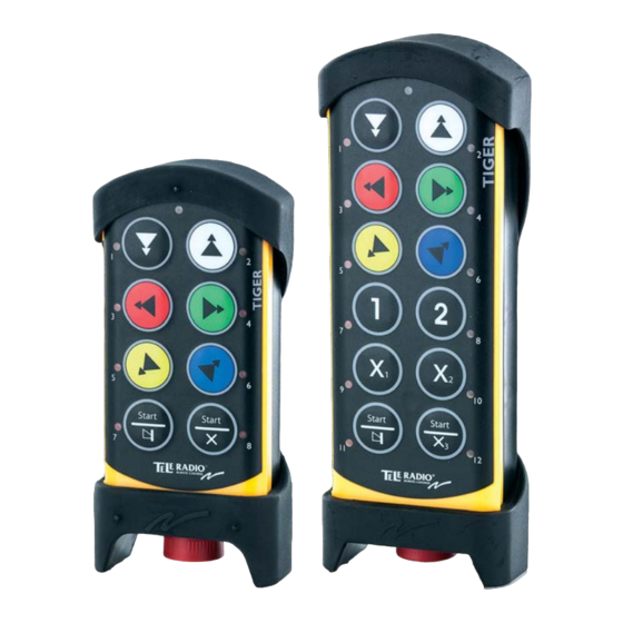
TG-TX-MNL8, TG-TX-MNR8, TG-TX-MXL12, TG-TX-MXR12 TRANSMITTER 1. Rubber cover 9. Button 6 2. Button 1 10. Right start button 3. Button 3 11. Button LEDs 4. Button 5 12. Stop button 5. Left start button 13. Button 7 6. Top LED 14. Button 8 7. - Page 37 ON/OFF SWITCH The TG-TX-MNL8, TG-TX-MNR8 transmitter has an on/off switch on the backside.The switch breaks the power supply from the battery. When in position 0/off, the transmitter cannot be started unless you connect the charger plug. When the transmitter is transported by airplane, the on/off switch must be in 0/off position.
- Page 38 TECHNICAL DATA NO. OF BUTTONS TG-TX-MNL8, TG-TX-MNR8 8 x 2-step buttons TG-TX-MXL12, TG-TX-MXR12 12 x 2-step buttons BATTERY TG-TX-MNL8, TG-TX-MNR8 Internal, rechargeable lithium-ion TG-TX-MXL12, TG-TX-MXR12 External, rechargeable lithium-ion ON/OFF SWITCH TG-TX-MNL8, TG-TX-MNR8 TG-TX-MXL12, TG-TX-MXR12 DUPLEX COMMUNICATION TG-TX-MNL8, TG-TX-MNR8, TG-TX-MDL10, Possible TG-TX-MXL12, TG-TX-MXR12 ...
- Page 39 OPERATING TIME (WITH CONTINUOUS USAGE) TG-TX-MNL8, TG-TX-MNR8, TG-TX-MXL12, 24 h. TG-TX-MXR12 IP CLASS TG-TX-MNL8, TG-TX-MNR8, TG-TX-MXL12, TG-TX-MXR12 SENSITIVITY TG-TX-MNL8, TG-TX-MNR8, TG-TX-MXL12, Better than -110 dBm TG-TX-MXR12 OPERATING TEMPERATURE TG-TX-MNL8, TG-TX-MNR8, TG-TX-MXL12, -20 - +55°C/ -4 - +130°F TG-TX-MXR12 ...
- Page 40 TRANSMITTER MEASUREMENTS TG-TX-MNL8,TG-TX-MNR8 76 mm (3 in) 46 mm (1.8 in) TG-TX-MXL12,TG-TX-MXR12 79 mm (3.1 in) 51 mm (2 in) 41 mm (1.6 in) - 40 -...
-
Page 41: Chapter 4: Installers Guide
Chapter 4: INSTALLERS GUIDE CHAPTER 4: INSTALLERS GUIDE SETTINGS FOR PIN CODES If you want to enable PIN codes for transmitter start-up protection, this can be done in the PC program Settings manager. All settings for PIN codes are made in the PC program. ... -
Page 42: Turn The Transmitter Off
Chapter 4: INSTALLERS GUIDE For digit: TG-TX-MNL8, TG-TX-MNR8, PRESS BUTTON: TG-TX-MXL12, TG-TX-MXR12, PRESS BUTTON: 4. WITHIN 3 MINUTES FROM PULLING OUT THE STOP BUTTON: Press a button to select the receiver(s) that you want to operate. The receiver(s) that was selected in the last session will be automatically selected, which is indicated by the corresponding LED(s) that light red. If no receiver(s) has been selected, the LEDs for all available receivers will flash red. -
Page 43: Login/Logout
LOGIN/LOGOUT NOTE! If you need to log out a transmitter that is lost or damaged, it is possible to log out from the receiver. We do not recommend this way of logging out. Contact your representative for assistance. NOTE! To be able to control a receiver, the transmitter must be registered in the receiver, and logged in to the receiver. -
Page 44: Register
When completed successfully, the top LED lights green. If not completed successfully within 25 seconds, the top LED lights red and the transmitter turns off. REGISTER WARNING! Do not perform this when the receiver is in a session with another transmitter. The radio communication may become disturbed or broken. -
Page 45: Erase
ERASE WARNING! If a transmitter is lost or becomes seriously damaged, it is possible to erase it from the receiver. We do not recommend this way. Contact your representative for assistance. NOTE! If the transmitter already have receivers registered, we recommend that you erase all receivers from the transmitter before starting the replacement. -
Page 46: Automatic Shutdown
NOTE! If the transmitter already have receivers registered, we recommend that you erase all receivers from the transmitter before starting the replacement. The receiver will automatically be stored in the same position as it was stored in the old transmitter. If this position is not available, the replacement will not take place. -
Page 47: Frequencies & Channels
3. Press the right start button. Keep pressed. 4. Press the stop button. 5. Release the right start button. The top LED flashes (green when the battery capacity is good, red when the battery capacity is poor) when in menu mode. - Page 48 DIGITS TG-TX-MNL8, TG-TX-MNR8: BUTTON TO PRESS TG-TX-MXL12, TG-TX-MXR12: BUTTON TO PRESS the right start button + 1 the right start button + 2 the right start button + 3 the right start button + 4 Show channel 1. Make sure that the stop button is pressed. ...
- Page 49 FREQUENCY BAND 433 MHZ Channel Frequency Channel Frequency 433.075 433.950 433.100 433.975 433.125 434.000 433.150 434.025 433.175 434.050 433.200 434.075 433.225 434.100 433.250 434.125 433.275 434.150 433.300 434.175 433.325 434.200 433.350 434.225 433.375 434.250 433.400 434.275 433.425 434.300 433.450 434.325 433.475 434.350 433.500 434.375 433.525...
- Page 50 FREQUENCY BAND 915 MHZ Frequency-hopping spread spectrum (FHSS) is a method of transmitting radio signals by rapidly switching a carrier among many frequency channels, using a pseudorandom sequence known to both transmitter and receiver. For further information about the frequencies used in this frequency band and about frequency-hopping, please contact your representative.
-
Page 51: Relay Functionality
RELAY FUNCTIONALITY NOTE! Momentary relay functionality is default. That means that the relay will only be activated when you press a button on the transmitter. When the button is released, the relay deactivates. Setting a relay to latching means that the relay gets activated every time that you press a button, but in this case the relay remains active until the button is pressed again. -
Page 52: Digital Inputs
DIGITAL INPUTS The digital inputs on the receiver are connected to the transmitter LEDs. If you need to make other settings for the digital inputs indications on the transmitter, please contact your representative for assistance. - 52 -... -
Page 53: Chapter 5: Operating Modes
Chapter 5: OPERATING MODES CHAPTER 5: OPERATING MODES SELECT OPERATING MODE NOTE! To select Operating mode, the PC program Settings manager must be used. Contact your representative for assistance. - 53 -... -
Page 54: Chapter 6: Load Select Modes
Chapter 6: LOAD SELECT MODES CHAPTER 6: LOAD SELECT MODES MAKE A LOAD SELECTION NOTE! Before starting to perform these settings, make sure that the stop relays are deactivated! 1. Make sure that the stop button is pressed. 2. Twist and pull out the stop button. The top LED lights (green when the battery capacity is good, red when the battery capacity is poor). - Page 55 LOAD SELECT MODE 0 LOAD SELECT MODE 1 - 55 -...
- Page 56 LOAD SELECT MODE 2 LOAD SELECT MODE 3 - 56 -...
- Page 57 LOAD SELECT MODE 4 LOAD SELECT MODE 5 - 57 -...
- Page 58 LOAD SELECT MODE 6 LOAD SELECT MODE 7 The loads are selected in the PC program Settings manager. When you start the transmitter, you can not switch loads. The LEDs on the transmitter do not indicate what load that is activated. - 58 -...
-
Page 59: Chapter 7: Battery Guide
CHARGE TG-TX-MNL8, TG-TX-MNR8 Charger plug in the back of the transmitter Charger plug in the back of the transmitter or in TG-TX-MXL12, TG-TX-MXR12 the Tele Radio 5 V DC charger unit CHARGING TEMPERATURE TG-TX-MNL8, TG-TX-MNR8, 0- 45°C/ 32-113 °F... - Page 60 CHARGE THE BATTERY 1.When approx. 10% of the battery capacity remains, the top LED lights red and the internal buzzer beeps 3 times. 2. Put the charger plug into the socket in the back of the transmitter. While charging, the top LED flashes red.
- Page 61 BATTERY PRECAUTIONS Observe the following general battery warnings: As batteries contains flammable substances such as lithium or other organic solvents, they may cause heating, rupture or ignition. Risk of explosion if battery is replaced with a battery of an incorrect type. ...
- Page 62 The Tele Radio AB products are covered by a guarantee/warranty against material, construction and manufacturing faults. During the guarantee/warranty period, Tele Radio AB may replace the product or faulty parts. Work under guarantee/warranty must be carried out by Tele Radio AB or by an authorized service centre specified by Tele Radio AB.
-
Page 63: Chapter 8: Certifications Chapter
Chapter 8: CERTIFICATIONS CHAPTER CHAPTER 8: CERTIFICATIONS CHAPTER FCC/IC FCC STATEMENT Statement for warning: To satisfy FCC RF exposure requirements, a separation distance of 20 cm or more should be maintained between the antenna of this device and persons during device operation. To ensure compliance, operations at closer than this distance is not recommended. - Page 64 Chapter 8: CERTIFICATIONS CHAPTER The radio module in this product is labelled with its own FCC ID and IC number. The FCC ID and IC is not visible when the radio module is installed inside another device. Therefore, the outside of the device into which the module is installed must also display a label referring to the radio module.
- Page 65 THE RADIO MODULE Each radio module is specifically designed to match a Tele Radio product in terms of physical dimensions, connection points, voltage levels, signal interface etc. To use the radio modules in non Tele Radio products is not permitted. The radio modules are designed to interface directly to the main board of the receiver/transmitter unit.
-
Page 66: Receiver Labels
RECEIVER LABELS PRODUCT LABEL ON THE RECEIVER You will find the product label on the outside of the enclosure of the receiver. FCC / IC LABEL IN THE RECEIVER The FCC/ IC label is placed on the radio module. The radio module is mounted inside the receiver. ... -
Page 67: Transmitters Labels
TRANSMITTERS LABELS PRODUCT LABEL IN THE TRANSMITTER You will find the product label in the back of the transmitter. TG-TX-MNR8 TG-TX-MXR12 - 67 -... - Page 68 FCC/IC LABEL IN THE TRANSMITTER The FCC/IC label is placed on the radio module. The radio module is mounted inside the transmitter. D00005-06: TG-TX-MNR8, TG-TX-MXR12 - 68 -...
-
Page 69: Ec/Eea Declaration Of Conformity
EC/EEA DECLARATION OF CONFORMITY - 69 -... - Page 70 - 70 -...
- Page 71 (THIS PAGE HAS BEEN INTENTIONALLY LEFT BLANK) - 71 -...
- Page 72 ...
Need help?
Do you have a question about the TG-T9-1 and is the answer not in the manual?
Questions and answers