Table of Contents
Advertisement
Installation instructions
TG-T14-4, TG-T14-5, TG-T14-6, TG-T14-7, TG-T14-8, TG-T14-9,
TG-T15-4, TG-T15-5, TG-T15-6, TG-T15-7, TG-T15-8, TG-T15-9
TG-R4-26 (TG-RX-MNLCAN), TG-R4-28 (TG-RX-MNRCAN), TG-R4-30 (TG-RX-MNPCAN), TG-R4-41 (TG-RX-
MNLJ1939), TG-R4-43 (TG-RX-MNRJ1939), TG-R4-45 (TG-RX-MNPJ1939, TG-R4-36 (TG-RX-MNLANA),
TG-R4-38 (TG-RX-MNRANA), TG-R4-40 (TG-RX-MNPANA)
LANGUAGE: English (original)
IM-TG2-RX009-CERT
Advertisement
Table of Contents

Subscribe to Our Youtube Channel
Related Manuals for Tele Radio TG-T14-4


Summary of Contents for Tele Radio TG-T14-4
-
Page 1: Installation Instructions
Installation instructions TG-T14-4, TG-T14-5, TG-T14-6, TG-T14-7, TG-T14-8, TG-T14-9, TG-T15-4, TG-T15-5, TG-T15-6, TG-T15-7, TG-T15-8, TG-T15-9 TG-R4-26 (TG-RX-MNLCAN), TG-R4-28 (TG-RX-MNRCAN), TG-R4-30 (TG-RX-MNPCAN), TG-R4-41 (TG-RX- MNLJ1939), TG-R4-43 (TG-RX-MNRJ1939), TG-R4-45 (TG-RX-MNPJ1939, TG-R4-36 (TG-RX-MNLANA), TG-R4-38 (TG-RX-MNRANA), TG-R4-40 (TG-RX-MNPANA) LANGUAGE: English (original) IM-TG2-RX009-CERT... -
Page 2: Table Of Contents
TG-RX-MNLANA, TG-RX-MNRANA, TG-RX-MNPANA base board receiver with an expan- sion board TG-RX-MNLCAN, TG-RX-MNRCAN, TG-RX-MNPCAN, TG-RX-MNLJ1939, TG-RX- MNRJ1939, TG-RX-MNPJ1939 base board receiver with CAN expansion board TG-T14-4, TG-T14-5, TG-T14-6, TG-T14-7, TG-T14-8, TG-T14-9, TG-T15-4, TG-T15-5, TG-T15-6, TG-T15-7, TG-T15-8, TG-T15-9 transmitter Chapter 4: INSTALLERS GUIDE Navigate in menu mode Enable PIN codes... -
Page 3: Chapter 1: Customer Information
During the guarantee/ warranty period, Tele Radio AB may replace the product or faulty parts with new. Work under guarantee/ warranty must be carried out by Tele Radio AB or by an authorized service center specified by Tele Radio AB. Contact your Tele Radio AB representative if you need support or service. - Page 4 WARNINGS & RESTRICTIONS WARNING! Tele Radio remote controls are often built into wider applications. We recommend that the system is provided with a wired emergency stop where necessary. NOTE! We recommend that the functionality of the STOP button is being tested at a regular basis: At a minimum, when used for 200 hours.
-
Page 5: Chapter 2: Safety Information
Chapter 2: SAFETY INFORMATION CHAPTER 2: SAFETY INFORMATION APPLICATION AREA FOR THE TIGER SYSTEM The Tele Radio AB Tiger remote control systems are aimed for remote controlling of lifting or mobile equipment where a high safety level is required. AUTHORIZATION BY PIN CODE ... -
Page 6: System Requirements
SAFETY INFORMATION (IN ENGLISH) System requirements The product holds a safety-related stop function that complies with the requirements for SIL3 according to IEC61508: The stop function deactivates all relays on the receiver when the stop button on the transmitter is pressed. The stop function is available on all Tiger systems. The maximum delay of the stop function is 500 ms. -
Page 7: Chapter 3: Product Pages
Chapter 3: PRODUCT PAGES CHAPTER 3: PRODUCT PAGES ANTENNA NOTE! For optimum performance: Place well away from metal objects, such as metal girders, high- voltage cables and other antennas. NOTE! For optimum performance, place the antennas as far away from each other as possible. The recommended distance is more than 1 meter. -
Page 8: Tg-Rx-Mnlana, Tg-Rx-Mnrana, Tg-Rx-Mnpana Base Board Receiver With An Expan- Sion Board
WARNING! The receiver must NOT be opened by any other than a qualified installer. Make sure to turn the electricity off before opening the receiver. WARNING! Tele Radio remote controls are often built into wider applications. We recommend that the system is provided with a wired emergency stop where necessary. ... - Page 9 Expansion board: 15. Terminal block for analogue outputs 23. Function relays 22-25 16. Indication LED for communication with the 24. Terminal block for digital outputs base board (green) 25. Terminal block for external analogue reference 17. Programming connector and isolated analogue supply 18.
- Page 10 TERMINAL BLOCK FOR INPUT POWER 1. 48-230 V AC 2. 48-230 V AC 3. (not used) 4. ~12-24 V AC/DC 5. negative terminal DC voltage* 6. ~+12-24 V AC/DC * use when digital inputs are connected to receiver ...
- Page 11 FUNCTION LEDS INDICATION IN OPERATING MODE Function LED Off On Indicates... X No transmitter is registered 1 (red) X One or more transmitters are registered X No transmitter is logged in 2 (yellow) X One transmitter is logged in 3 (green) ...
- Page 12 TERMINAL BLOCK FOR EXTERNAL ANALOGUE REFERENCE AND ISOLATED ANALOGUE SUPPLY How to connect to the terminal block depends on the configurations made to the receiver. Please, contact your Tele Radio representative for further assistance. 0 to +10V analogue output, internal DC/DC converter on: 50. Unconnected 51.
- Page 13 25-75% or 10-90% output****: 50. Negative supply 51. Unconnected 52. Positive supply * Analogue output reference will follow this voltage. If unconnected, the analogue output reference will be in the middle of the external supply voltage. ** External supply voltage of 22-35V DC is required to achieve full -10 to +10V output. *** External supply voltage shall not be connected.
- Page 14 TERMINAL BLOCK FOR DIGITAL INPUTS AND GROUND CONNECTIONS 77. Digital input 3 80. GND 78. Digital input 4 81. GND 79. Digital input 5 82. GND TERMINAL BLOCK FOR ANALOGUE INPUTS 83. Analogue input 1 84. Analogue input 2 85. Analogue GND TERMINAL BLOCK FOR ANALOGUE OUTPUTS ...
- Page 15 BASE BOARD R ELAY LEDS These LEDs light when the corresponding stop and function relays on the base board are activated. See list for corresponding base board relay. LED 1 = function relay 1 LED 2 = function relay 2 ...
- Page 16 TECHNICAL DATA Number of stop relays 2 (potential free*, 16A, 250VAC) Number of function relays 7 (potential free*, 10A, 250VAC) Digital inputs Input power 48-230V AC, 12-24V AC/DC Transistor output Duplex communication Possible Max. number of registered 15 (only one transmitter at a time) transmitters IP class Size...
-
Page 17: Tg-Rx-Mnlcan, Tg-Rx-Mnrcan, Tg-Rx-Mnpcan, Tg-Rx-Mnlj1939, Tg-Rx- Mnrj1939, Tg-Rx-Mnpj1939 Base Board Receiver With Can Expansion Board
WARNING! The receiver must NOT be opened by any other than a qualified installer. Make sure to turn the electricity off before opening the receiver. WARNING! Tele Radio remote controls are often built into wider applications. We recommend that the system is provided with a wired emergency stop where necessary. ... - Page 18 Expansion board: 15. Terminal block for internal power supply 18. CAN run LED 16. Programming connector 19. CAN error LED 17. Power LED 20. Terminal block for CAN signals - 18 -...
- Page 19 TERMINAL BLOCK FOR INPUT POWER 1. 48-230 V AC 2. 48-230 V AC 3. (not used) 4. ~12-24 V AC/DC 5. negative terminal DC voltage* 6. ~+12-24 V AC/DC * use when digital inputs are connected to receiver ...
- Page 20 FUNCTION LEDS INDICATION IN OPERATING MODE Function LED Off On Indicates... X No transmitter is registered 1 (red) X One or more transmitters are registered X No transmitter is logged in 2 (yellow) X One transmitter is logged in 3 (green) ...
- Page 21 TECHNICAL DATA Number of stop relays 2 (potential free*, 16A, 250VAC) Number of function relays 7 (potential free*, 10A, 250VAC) Digital inputs Input power 48-230V AC, 12-24V AC/DC Transistor output Duplex communication Possible Max. number of registered 15 (only one transmitter at a time) transmitters IP class Size...
- Page 22 CURRENT CONSUMPTION Input power Min.* Max.** 12V AC 0.06A 0.4A 24V AC 0.03A 0.2A 48V AC 0.02A 0.09A 115V AC 0.008A 0.04A 230V AC 0.006A 0.03A 12V DC 0.06A 0.3A 24V DC 0.03A 0.2A * Minimum current consumption= Receiver powered, no radio session established, nothing else activated on the receiver ** Maximum current consumption= All relays activated on the receiver - 22 -...
- Page 23 RECEIVER MEASUREMENTS TG-RX-MNLANA, TG-RX-MNRANA, TG-RX-MNPANA 176 mm (6.9 in) Ø5.5 mm 154 mm (6 in) (0.2 in) Ø15 mm (0.6 in) Ø5.5 mm (0.2 in) - 23 -...
- Page 24 TG-RX-MNLCAN, TG-RX-MNRCAN, TG-RX-MNPCAN, TG-RX-MNLJ1939, TG-RX-MNRJ1939, TG-RX-MNPJ1939 176 mm (6.9 in) Ø5.5 mm 154 mm (6 in) (0.2 in) Ø9 mm (0.4 in) Ø5.5 mm (0.2 in) - 24 -...
-
Page 25: Tg-T15-6, Tg-T15-7, Tg-T15-8, Tg-T15-9 Transmitter
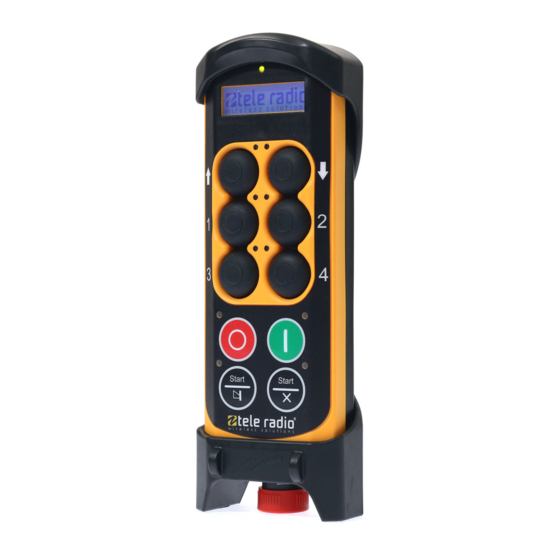
7. Left start button 16. Button 9 (safe button**) 8. Top led 17. Button 10 (safe button**) 9. Button 2 * On TG-T14-4, TG-T14-5, TG-T14-6, TG-T14-7, TG-T14-8, TG-T14-9 ** On TG-T15-4, TG-T15-5, TG-T15-6, TG-T15-7, TG-T15-8, TG-T15-9 - 25 -... - Page 26 0/off position. The switch should not be used as an on/off button for the transmitter. To turn the transmitter off, use the stop button. BUTTON TRANSMITTER BACKSIDE TG-T14-4 TG-T15-4 TG-T14-5 TG-T15-5 TG-T14-6 TG-T15-6 TG-T14-7 TG-T15-7 TG-T14-8 TG-T15-8...
- Page 27 TECHNICAL DATA NO. OF BUTTONS TG-T14-4, TG-T14-5, TG-T14-6, TG-T14-7, TG- 4 x 2-step buttons, 6 analogue buttons T14-8, TG-T14-9 TG-T15-4, TG-T15-5, TG-T15-6, TG-T15-7, TG- 4 x 2-step buttons, 8 analogue buttons T15-8, TG-T15-9 BATTERY TG-T14-4, TG-T14-5, TG-T14-6, TG-T14-7, TG- T14-8, TG-T14-9, TG-T15-4, TG-T15-5, TG-...
- Page 28 25 kHz TG-T14-5, TG-T14-8, TG-T15-5, TG-T15-8 TG-T14-6, TG-T14-9, TG-T15-6, TG-T15-9 5 MHz OPERATING TIME (WITH CONTINUOUS USAGE) TG-T14-4, TG-T14-5, TG-T14-6, TG-T14-7, TG- T14-8, TG-T14-9, TG-T15-4, TG-T15-5, TG- 16 h. T15-6, TG-T15-7, TG-T15-8, TG-T15-9 IP CLASS TG-T14-4, TG-T14-5, TG-T14-6, TG-T14-7, TG-...
- Page 29 TRANSMITTER MEASUREMENTS TG-T14-4, TG-T14-5, TG-T14-6, TG-T14-7, TG-T14-8, TG-T14-9 TG-T15-4, TG-T15-5, TG-T15-6, TG-T15-7, TG-T15-8, TG-T15-9 - 29 -...
-
Page 30: Chapter 4: Installers Guide
Chapter 4: INSTALLERS GUIDE CHAPTER 4: INSTALLERS GUIDE NAVIGATE IN MENU MODE To navigate when in menu mode: Press... to... Button 1 Step down Button 2 Step up Button 3 Step left/ go back Button 4 Step right The left start button Select/ confirm The right start button Exit... -
Page 31: Create Pin Codes
CREATE PIN CODES NOTE! You can store up to 10 PIN codes in the transmitter. NOTE! '0000' is not a valid PIN code. 1. Make sure that the stop button is pressed. 2. Twist and pull out the stop button. The top LED lights (green when the battery capacity is good, red when the battery capacity is poor). -
Page 32: Erase Pin Codes
ERASE PIN CODES 1. Make sure that the stop button is pressed. 2. Twist and pull out the stop button.The LEDs light (green when the battery capacity is good, red when the battery capacity is poor). 3. Press the right start button. Keep pressed. ... -
Page 33: Start The Transmitter In Operating Mode
START THE TRANSMITTER IN OPERATING MODE 1. Make sure that the stop button is pressed 2. Twist and pull out the stop button. The top LED lights (green when the battery capacity is good, red when the battery capacity is poor). 3. If PIN codes are used for authorization: Go to the next section. ... -
Page 34: Start The Transmitter In Operating Mode With Pin Codes
The top LED lights (green when the battery capacity is good, red when the battery capacity is poor). 3. WITHIN 3 MINUTES : Enter the PIN code (4 digits) by pressing the buttons according to the table. For digit: TG-T14-4, TG-T14-5, TG-T14-6, TG-T14-7, TG-T14-8, TG-T14-9, PRESS BUTTON: TG-T15-4, TG-T15-5, TG-T15-6, TG-T15-7, TG-T15-8, TG-T15-9, PRESS BUTTON: ... -
Page 35: Login/Logout
LOGIN/LOGOUT NOTE! When the transmitter has established radio communication with one or more receivers, you can make a Quick logout from those receivers. Note that the Quick logout will log the transmitter out from all receivers that are participating in the session. ... -
Page 36: Register
Logout from menu mode 1. Make sure that the stop button is pressed. 2. Twist and pull out the stop button. The top LED lights (green when the battery capacity is good, red when the battery capacity is poor). ... -
Page 37: Erase
The top LED flashes (green when the battery capacity is good, red when the battery capacity is poor) when in menu mode. 9. Go to [Register]. 10. Select an empty slot and confirm by pressing the left start button. The display shows [Registering] . ... -
Page 38: Replace
REPLACE WARNING! Do not perform this when the receiver is in a session with another transmitter. The radio communication may become disturbed or broken. NOTE! You can replace a registered transmitter with another transmitter without having access to the receiver. -
Page 39: Automatic Shutdown
AUTOMATIC SHUTDOWN NOTE! Turning on automatic shutdown can save battery capacity by automatically turning the transmitter off when no function has been activated for a set time. Set the time for automatic shutdown 1. Make sure that the stop button is pressed. ... -
Page 40: Frequencies & Channels
FREQUENCIES & CHANNELS NOTE! If your system is transmitting on the frequency bands 433MHz eller 2.4 GHz, the receiver will automatically detect and switch to the same channel that the transmitter is using. If your system is transmitting on the 915 MHz frequency band, you have to switch bank in the receiver by using the PC program Settings manager. - Page 41 FREQUENCY BAND 433 MHZ Channel Frequency Channel Frequency 433.075 433.950 433.100 433.975 433.125 434.000 433.150 434.025 433.175 434.050 433.200 434.075 433.225 434.100 433.250 434.125 433.275 434.150 433.300 434.175 433.325 434.200 433.350 434.225 433.375 434.250 433.400 434.275 433.425 434.300 433.450 434.325 433.475 434.350 433.500 434.375 433.525...
- Page 42 FREQUENCY BAND 915 MHZ Frequency-hopping spread spectrum (FHSS) is a method of transmitting radio signals by rapidly switching a carrier among many frequency channels, using a pseudorandom sequence known to both transmitter and receiver. For further information about the frequencies used in this frequency band and about frequency-hopping, please contact your representative.
-
Page 43: Relay Functionality
RELAY FUNCTIONALITY NOTE! If Operating mode 0 is selected, you can not make these settings. Contact your representative for assistance. NOTE! Momentary relay functionality is default. That means that the relay will only be activated when you press a button on the transmitter. When the button is released, the relay deactivates. Setting a relay to latching means that the relay gets activated every time that you press a button, but in this case the relay remains active until the button is pressed again. -
Page 44: Digital Inputs
DIGITAL INPUTS The digital inputs on the receiver are connected to the transmitter LEDs. If you need to make other settings for the digital inputs indications on the transmitter, please contact your representative for assistance. - 44 -... -
Page 45: Chapter 5: Operating Modes
Chapter 5: OPERATING MODES CHAPTER 5: OPERATING MODES SELECT OPERATING MODE NOTE! All receivers in this manual are intended to be customized. Contact your representative for assistance. - 45 -... -
Page 46: Chapter 6: Load Select Modes
Chapter 6: LOAD SELECT MODES CHAPTER 6: LOAD SELECT MODES LOAD SELECT MODE NOTE! Before starting to perform these settings, make sure that the stop relays are deactivated! 1. Make sure that the stop button is pressed. 2.Twist and pull out the stop button. The top LED lights (green when the battery capacity is good, red when the battery capacity is poor). - Page 47 LOAD SELECT MODE 0 LOAD SELECT MODE 1 - 47 -...
- Page 48 LOAD SELECT MODE 2 LOAD SELECT MODE 3 - 48 -...
- Page 49 LOAD SELECT MODE 4 LOAD SELECT MODE 5 - 49 -...
- Page 50 LOAD SELECT MODE 6 LOAD SELECT MODE 7 The loads are selected in the PC program Settings manager. When you start the transmitter, you cannot switch loads. The LEDs on the transmitter do not indicate which load is activated. - 50 -...
-
Page 51: Chapter 7: Battery Guide
Chapter 7: BATTERY GUIDE CHAPTER 7: BATTERY GUIDE BATTERY INFORMATION TYPE OF BATTERY TG-T14-4, TG-T14-5, TG-T14-6, TG-T14-7, TG- Internal, rechargeable lithium-ion T14-8, TG-T14-9, TG-T15-4, TG-T15-5, TG- battery T15-6, TG-T15-7, TG-T15-8, TG-T15-9 OPERATING TIME TG-T14-4, TG-T14-5, TG-T14-6, TG-T14-7, TG- T14-8, TG-T14-9, TG-T15-4, TG-T15-5, TG- Approx. - Page 52 2. Put the charger plug into the socket in the back of the transmitter. While charging, the top LED flashes in red. If the transmitter has an external battery, you can also remove the battery and charge it in the Tele Radio 5V DC charging unit. ...
- Page 53 (WEEE), Tele Radio AB strives to minimize the use of hazardous materials, promotes reuse and recycling, and reduces emissions to air, soil and water. When a commercially viable alternative is available, Tele Radio AB strives to restrict or eliminate substances and materials that pose an environmental, health or safety risk.
- Page 54 The Tele Radio AB products are covered by a guarantee/warranty against material, construction and manufacturing faults. During the guarantee/warranty period, Tele Radio AB may replace the product or faulty parts. Work under guarantee/warranty must be carried out by Tele Radio AB or by an authorized service centre specified by Tele Radio AB.
-
Page 55: Chapter 8: Certifications Chapter
Chapter 8: CERTIFICATIONS CHAPTER CHAPTER 8: CERTIFICATIONS CHAPTER FCC/ IC FCC STATEMENT Statement for warning: To satisfy FCC RF exposure requirements, a separation distance of 20 cm or more should be maintained between the antenna of this device and persons during device operation. To ensure compliance, operations at closer than this distance is not recommended. - Page 56 Chapter 8: CERTIFICATIONS CHAPTER The radio module in this product is labelled with its own FCC ID and IC number. The FCC ID and IC is not visible when the radio module is installed inside another device. Therefore, the outside of the device into which the module is installed must also display a label referring to the radio module.
- Page 57 THE RADIO MODULE Each radio module is specifically designed to match a Tele Radio product in terms of physical dimensions, connection points, voltage levels, signal interface etc. To use the radio modules in non Tele Radio products is not permitted. The radio modules are designed to interface directly to the main board of the receiver/transmitter unit.
- Page 58 PRODUCT LABEL ON THE RECEIVER You will find the product label on the outside of the enclosure of the receiver. FCC/IC LABEL I N THE RECEIVER The FCC/IC label is placed on the radio module. The radio module is mounted inside the receiver. ...
- Page 59 PRODUCT LABEL ON THE TRANSMITTER You will find the product label in the back of the transmitter. - 59 -...
- Page 60 FCC/IC LABEL IN THE TRANSMITTER The FCC/IC label is placed on the radio module. The radio module is mounted inside the transmitter. D00005-06: TG-T14-8, TG-T15-8 D00005-09: TG-T14-9, TG-T15-9 The FCC/IC label is placed on the main board. The main board is mounted inside the transmitter. ...
-
Page 61: Ec/Eea Declaration Of Conformity
EC/EEA DECLARATION OF CONFORMITY - 61 -... - Page 62 - 62 -...
- Page 63 - 63 -...
- Page 64 - 64 -...
- Page 65 (THIS PAGE HAS BEEN INTENTIONALLY LEFT BLANK) - 65 -...
- Page 66 ...
Need help?
Do you have a question about the TG-T14-4 and is the answer not in the manual?
Questions and answers