
Related Manuals for Tele Radio Tiger T2


Summary of Contents for Tele Radio Tiger T2
-
Page 1: Installation Instructions
Installation instructions RECEIVERS: R00004-05, R00004-10, TRANSMITTERS: T00009-22, T00011-24 LANGUAGE: English (original) IM-TG2-CE001-A01-EN... - Page 2 CONTENTS Chapter 1: CUSTOMER INFORMATION Chapter 2: SYSTEM INFORMATION Application area for the Tiger system Chapter 3: PRODUCT PAGES Receiver R00004-05 Receiver R00004-10 with a relay expansion board Transmitters T00009-22, T00011-24 Technical data On/off switch Chapter 4: FCC/ IC INFORMATION FCC/IC INFORMATION for the T00011-24, R00004-10 Product label and placement on the transmitter Product label and placement on the receiver FCC/IC label and placement on the transmitter...
-
Page 3: Chapter 1: Customer Information
During the guarantee/ warranty period, Tele Radio AB may replace the product or faulty parts with new. Work under guarantee/ warranty must be carried out by Tele Radio AB or by an authorized service center specified by Tele Radio AB. Contact your Tele Radio AB representative if you need support or service. - Page 4 WARNINGS & RESTRICTIONS IMPORTANT! Tele Radio remote controls are often built into wider applications. We recommend that the system is provided with a wired emergency stop where necessary. NOTE! We recommend that the functionality of the STOP button is being tested at a regular basis: At a minimum, when used for 200 hours.
-
Page 5: Chapter 2: System Information
CHAPTER 2: SYSTEM INFORMATION APPLICATION AREA FOR THE TIGER SYSTEM The Tele Radio AB Tiger remote control systems are aimed for remote controlling of lifting or mobile equipment where a high safety level is required. AUTHORIZATION BY PIN CODE ... -
Page 6: Chapter 3: Product
WARNING! The receiver must NOT be opened by any other than a qualified installer. Make sure to turn the electricity off before opening the receiver. IMPORTANT! Tele Radio remote controls are often built into wider applications. We recommend that the system is provided with a wired emergency stop where necessary. ... - Page 7 Terminal block for input power Terminal block for mixed I/O 32. +12V DC 38. Digital input 2 33. +5V DC 39. GND 34. GND 40. +3.3V DC 35. GND 41. RS485A 36. Digital input 1 42.
- Page 8 Technical data R00004-05 Number of stop relays 2 (16A) Number of function relays 7 (potential free*, 8A) Digital inputs Transistor output Duplex communication Duplex or simplex communication possible Max. number of transmitters 15 Operating frequency 2405-2480 MHz Number of channels/ banks Channel separation 5 MHz IP class...
-
Page 9: Receiver R00004-10 With A Relay Expansion Board
WARNING! The receiver must NOT be opened by any other than a qualified installer. Make sure to turn the electricity off before opening the receiver. IMPORTANT! Tele Radio remote controls are often built into wider applications. We recommend that the system is provided with a wired emergency stop where necessary. ... - Page 10 Expansion board: 15. Terminal block for digital inputs 19. Select button (OK) 16. Relay LEDs 10-19 20. Function button (Cancel) 17. Function relays 10-19 21. Programming connector 18. LEDs representing stop relays 1-2 and func- 22. Power LED (yellow) tion relays 1-7 on the base board ...
- Page 11 Current consumption Input power Min.* Max.** 12V AC 0.06A 24V AC 0.03A 0.3A 48V AC 0.02A 0.2A 115V AC 0.009A 0.07A 230V AC 0.008A 0.04A 12V DC 0.06A 0.6A 24V DC 0.03A 0.2A * Minimum current consumption= Receiver powered, no radio session established, nothing else activated on the receiver ** Maximum current consumption= All relays activated on the receiver ...
- Page 12 Function LEDs indication in operating mode FUNCTION LED OFF INDICATES No transmitter is registered One or more transmitters are registered No transmitter is logged in One transmitter is logged in Receiving correct RS485 data Settings in the safety CPUs conform to SIL3 Settings in the safety CPUs do NOT con- ...
-
Page 13: Transmitters T00009-22, T00011-24
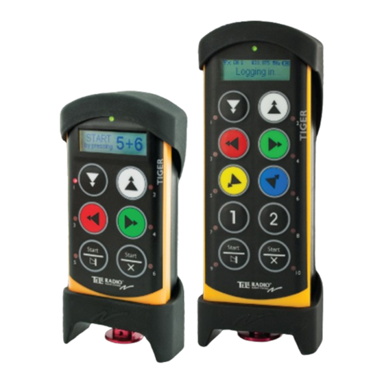
TRANSMITTERS T00009-22, T00011-24 1. Rubber cover 9. Button 6 (T00009-22: right start button) 2. Display 10. Button LEDs 3. Button 1 11. Stop button 4. Button 3 12. Button 7* 5. Button 5 (T00009-22 : left start button) 13. -
Page 14: On/Off Switch
ON/OFF SWITCH The T00009-22 transmitter has an on/off switch on the backside. The on/off switch has 2 positions: 1= on 0= off The on/off switch breaks the power supply from the battery. When in position 0/off, the transmitter can not be started unless you connect the charger plug. -
Page 15: Chapter 4: Fcc/ Ic Information
Chapter 4: FCC/ IC INFORMATION CHAPTER 4: FCC/ IC INFORMATION FCC/IC INFORMATION FOR THE T00011-24, R00004-10 Product label and placement on the transmitter T00011-24 You will find the product label in the back of the transmitter (see picture below). ... -
Page 16: Fcc/Ic Label And Placement On The Transmitter
Chapter 4: FCC/ IC INFORMATION FCC/IC label and placement on the transmitter T00011-24 The FCC/ IC label is placed on the radio module. The radio module is mounted inside the transmitter. L’étiquette FCC/IC est placée sur le module radio. Le module radio est monté à l’intérieur du récep- teur. -
Page 17: Fcc Statement
Function Each receiver and transmitter unit in the Tele Radio Tiger product range, contains a radio module that is specifically designed to match a Tele Radio Tiger unit in terms of physical dimensions, connection points, voltage levels, signal interface etc. To use the radio modules in non Tele Radio products is not permitted. - Page 18 Chapter 4: FCC/ IC INFORMATION Caution: The user is cautioned that changes or modifications not expressly approved by the party responsible for compliance could void the user's authority to operate the equipment. This device complies with Industry Canada licence-exempt RSS standard(s) and Part 15 of the FCC Rules.
-
Page 19: Chapter 5: Installers Guide
Chapter 5: INSTALLERS GUIDE CHAPTER 5: INSTALLERS GUIDE CREATE PIN CODES NOTE! You can store up to 10 PIN codes in the transmitter. NOTE! '0000' is not a valid PIN code. 1. Make sure that the stop button is pressed. ... -
Page 20: Show Registered Pin Codes
Chapter 5: INSTALLERS GUIDE 7. Scroll the list to select the PIN code that you want to erase. MOVE JOYSTICK step up down step down 8. Select by pressing the left start button. 9. Confirm by pressing the left start buttons. ... -
Page 21: Start The Transmitter In Operating Mode With A Pin Code
Chapter 5: INSTALLERS GUIDE 7. When radio communication has been established, the top LED lights (green when the battery capacity is good, red when the battery capacity is poor). If radio communication is not established within 25 seconds, the transmitter turns off. ... -
Page 22: Navigate In Menu Mode
NAVIGATE IN MENU MODE To navigate when in menu mode, press: Button 1 Step down Button 2 Step up Button 3 Step left/ go back Button 4 Step right The left start button Select/ confirm The right start button Exit ... -
Page 23: Turn The Transmitter Off
4. Press the stop button. 5. Release the right start button. The top LED flashes (green when the battery capacity is good, red when the battery capacity is poor) when in menu mode. 6. Go to [Logout]. 7. -
Page 24: Number Of Transmitters Registered In The Receiver
The top LED flashes (green when the battery capacity is good, red when the battery capacity is poor) when in menu mode. 9. Go to [Register]. 10. Select by pressing the left start button. 11. Select a receiver. Confirm by pressing the left start button. The display shows [Registering] while the process is ongoing. -
Page 25: Replace
6. Go to [Erase]. 7. Select by pressing the left start button . 8. Select a receiver. Confirm by pressing the left start button. The display shows [Erasing] while the process is ongoing. If the erasing fails, the display shows [FAILED]. The transmitter turns off. If the erasing succeeds, the display shows [OK]. -
Page 26: Automatic Shutdown
8.Press the left start button. The display shows [Replacing] while the process is ongoing. If the replacement fails, the display shows [FAILED].The transmitter turns off. If the replacement succeeds, the display shows [OK]. The transmitter turns off. AUTOMATIC SHUTDOWN ... -
Page 27: Frequency Band 2.4 Ghz
FREQUENCY BAND 2.4 GHZ CHANNEL FREQUENCY 2405 2410 2415 2420 2425 2430 2435 2440 2445 2450 2455 2460 2465 2470 2475 2480 RELAY FUNCTIONALITY NOTE! If Operating mode 0 is selected, you can not make these settings. Contact your representative for assistance. -
Page 28: Interlocking
6. Press the receiver Select button to step to the next available relay. When you have stepped through all the available relays, the receiver exits the LED menu and restarts. Interlocking What function relays that are available for interlocking, i.e. that can be blocked or prioritized when pressed at the same time, depends on what Operating mode that is selected in the receiver. -
Page 29: Chapter 6: Battery Guide
Approx. 16 h. with continuous usage Charger plug in the back of the transmitter Charge Charger plug in the back of the transmitter or in the Tele Radio 5 V DC charger unit Charging temperature 0- 45°C/ 32-113 °F 0- 45°C/ 32-113 °F ... -
Page 30: Charge The Battery
CHARGE THE BATTERY 1.When approx. 10% of the battery capacity remains, the top LED lights red and the internal buzzer beeps 3 times. 2. Put the charger plug into the socket in the back of the transmitter. While charging, the top LED flashes red. -
Page 31: Removal Of Internal Battery
(WEEE), Tele Radio AB strives to minimize the use of hazardous materials, promotes reuse and recycling, and reduces emissions to air, soil and water. When a commercially viable alternative is available, Tele Radio AB strives to restrict or eliminate substances and materials that pose an environmental, health or safety risk. -
Page 32: Guarantee, Service, Repairs And Maintenance
The Tele Radio AB products are covered by a guarantee/warranty against material, construction and manufacturing faults. During the guarantee/warranty period, Tele Radio AB may replace the product or faulty parts. Work under guarantee/warranty must be carried out by Tele Radio AB or by an authorized service centre specified by Tele Radio AB. - Page 33 ...
Need help?
Do you have a question about the Tiger T2 and is the answer not in the manual?
Questions and answers
On a tiger 2 remote. I had to buy a new charger from store and it said to make sure the correct polarity . So is inside hot or outside?