Summary of Contents for Tele Radio R00008-22
-
Page 1: Installation Instructions
TELE RADIO AB PANTHER Installation instructions RECEIVER: R00008-22 TRANSMITTER: T00013-10 LANGUAGE: English (original) IM-PN-CE002-A03-EN... -
Page 2: Chapter 1: Customer Information
These instructions are published by Tele Radio AB without any guarantee. The instructions may be removed or revised by Tele Radio AB at any time and without further notice. Corrections and additions will be added to the latest version of the instruction. -
Page 3: Maintenance
Warnings & restrictions IMPORTANT! Tele Radio remote controls are often built into wider applications. We recommend that the system is provided with a wired emergency stop where necessary. NOTE! We recommend that the functionality of the STOP button is being tested at a regular basis: At a minimum, when used for 200 hours. -
Page 4: Chapter 2: System Information
Chapter 2: SYSTEM INFORMATION CHAPTER 2: SYSTEM INFORMATION Application area for the Panther system The Tele Radio AB Panther remote control systems are aimed for remote controlling of industrial equipment where a high flexibility is required. - 4 -... -
Page 5: Chapter 3: Product Pages
WARNING! The receiver must NOT be opened by any other than a qualified installer. Make sure to turn the electricity off before opening the receiver. R00008-22 BASE BOARD RECEIVER 1. Function LEDs (1= red, 2= yellow, 3= green, 4= orange) 6. -
Page 6: Analogue Expansion Board
ANALOGUE EXPANSION BOARD 11. Terminal block for analogue inputs/ outputs 12. Indication LED for communication with the base board (green) -
Page 7: Components Description
COMPONENTS DESCRIPTION TERMINAL BLOCK FOR DIGITAL INPUTS Digital input Digital input Digital input Digital input Digital input Digital input Digital input Digital input TERMINAL BLOCK FOR MOTOR 1 Input power GND Motor output M1A Motor output M1B Input power 12-24 V DC... -
Page 8: Terminal Block For Analogue Inputs/ Outputs
TERMINAL BLOCK FOR MOTOR 2 Input power GND Motor output M2A Motor output M2B Input power 12-24 V DC TERMINAL BLOCK FOR ANALOGUE INPUTS/ OUTPUTS Analogue input Analogue input +3.3 V DC Analogue output 1 ... -
Page 9: Technical Data
TECHNICAL DATA Number of function relays 1 (potential free*, 8A) Digital inputs Number of DC motor controls Number of analogue outputs Number of analogue inputs Duplex communication 12 V DC: Min.** 0.5mA/ Max.*** 20A Min./max. current consumtion 24 V DC: Min.** 0.5mA/ Max.*** 20 A Operating frequency 2405-2480 MHz Number of radio channels... -
Page 10: Measurements For Mounting Of The Receiver
MEASUREMENTS FOR MOUNTING OF THE RECEIVER ... -
Page 11: Transmitter Measurements
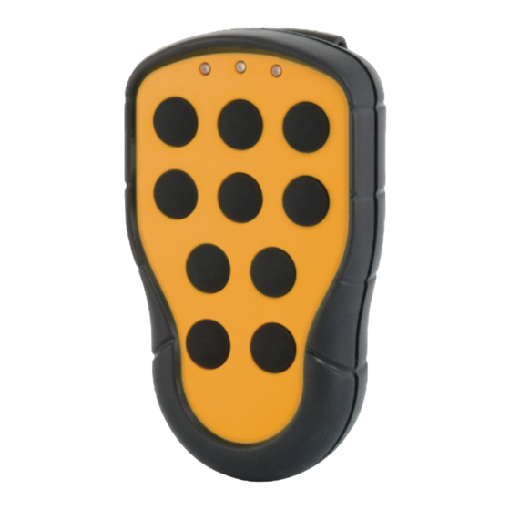
TRANSMITTER T00013-10 1. LED 1 3. LED 2 2. Top LED 4. 1-step push buttons 1-10 TRANSMITTER MEASUREMENTS ... -
Page 12: On/Off Switch
TECHNICAL DATA No. of buttons 10 x 1-step buttons On/off switch Size 114.5 x 66 x 37.5 mm./ 4.5 x 2.6 x 1.48 in. Weight 135 g./ 0.3 lbs. (excluding batteries) Number of channels 16 (channel 11-26) Operating frequency 2405-2480 MHz. -
Page 13: Fcc/ Ic Label
FCC/ IC LABEL The FCC IC label is placed in the back of the transmitter. See picture. FCC statement Statement for warning: Caution: The user is cautioned that changes or modifications not expressly approved by the party responsible for compliance could void the user's authority to operate the equipment. -
Page 14: Chapter 4: Installers Guide
CHAPTER 4: INSTALLERS GUIDE START THE TRANSMITTER 1. Press button 9 (the on button) for at least 1 second. 2. Release button 9 (the on button) when the top LED turns green. 3. The transmitter is started. ... -
Page 15: Chapter 5: Battery Guide
Chapter 5: BATTERY GUIDE CHAPTER 5: BATTERY GUIDE BATTERY INFORMATION WARNING! Do not recharge the batteries. Attempts to recharge may cause rupture or the leaking of hazardous liquids, which will corrode the equipment. IMPORTANT! Electronics and batteries must be physically separated before disposal. Make sure that electronics or batteries are not thrown in the household waste. -
Page 16: Battery Precautions
The Tele Radio AB products are covered by a guarantee/warranty against material, construction and manufacturing faults. During the guarantee/warranty period, Tele Radio AB may replace the product or faulty parts. Work under guarantee/warranty must be carried out by Tele Radio AB or by an authorized service centre specified by Tele Radio AB. - Page 17 Chapter 5: BATTERY GUIDE CE MARKING This product complies with current European directives and standards. - 17 -...
- Page 18 ...


Need help?
Do you have a question about the R00008-22 and is the answer not in the manual?
Questions and answers