
Related Manuals for Tele Radio T70 Series


Summary of Contents for Tele Radio T70 Series
- Page 1 Installation instructions T70RX-03AIB, T70RX-03AWB, T70TX-02TTB, T70TX-03STB, T70TX-06TTB LANGUAGE: English (original) IM-T70-RX001-A01-EN...
-
Page 2: Table Of Contents
CONTENTS Chapter 1: CUSTOMER INFORMATION Chapter 2: PRODUCT PAGES Receiver description T70RX-03AIB, T70RX-03AWB Quick Fuse Terminal block for input power Current consumption Technical data Transmitter description Technical data Change batteries Start the transmitter Turn the transmitter off Automatic shutdown Register Erase Switch frequency Frequency banks... -
Page 3: Chapter 1: Customer Information
During the guarantee/ warranty period, Tele Radio AB may replace the product or faulty parts with new. Work under guarantee/ warranty must be carried out by Tele Radio AB or by an authorized service center specified by Tele Radio AB. Contact your Tele Radio AB representative if you need support or service. - Page 4 WARNINGS & RESTRICTIONS IMPORTANT! Tele Radio remote controls are often built into wider applications. We recommend that the system is provided with a wired emergency stop where necessary. INSTALLING, CONNECTING AND MOUNTING Allow only licensed or qualified personnel to install the product.
-
Page 5: Chapter 2: Product Pages
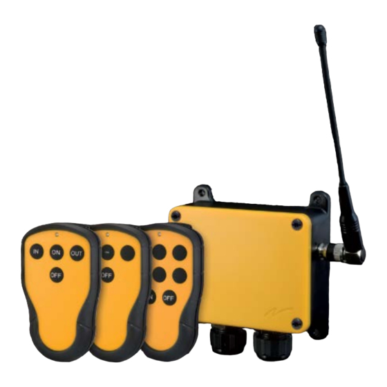
Chapter 2: PRODUCT PAGES CHAPTER 2: PRODUCT PAGES RECEIVER DESCRIPTION T70RX-03AIB, T70RX-03AWB WARNING! The receiver must NOT be opened by any other than a qualified installer. Make sure to turn the electricity off before opening the receiver. 1. -
Page 6: Quick Fuse
QUICK FUSE NOTE! With the 10 A fuse mounted and the receiver powered, voltage from the middle power supply connection pin (12-24V AC/DC fused) is fed through the fuse to relay number 1 (pin 2, NO). ... -
Page 7: Terminal Block For Input Power
TERMINAL BLOCK FOR INPUT POWER CURRENT CONSUMPTION Input power Minimum Maximum 12V DC 25 mA 100 mA 24V DC 15 mA 50 mA 24V AC 15 mA 50 mA TECHNICAL DATA Input power 12-24V AC/DC Function relays 3 potential free*, 8 A ACI Radiotype Superheterodyne... -
Page 8: Transmitter Description
TRANSMITTER DESCRIPTION 70TX-02TTB, T70TX-03STB T70TX-06TTB 1.Push button 1 6. Push button 6 2. Push button 2 7. Push button 7 3. Push button 3 8. Push button 8 4. Push button 4 9. Red LED 5. Push button 5 ... -
Page 9: Change Batteries
CHANGE BATTERIES 1. Remove the (a) clip (2 screws). 2. Remove the (b ) battery lid (2 screws). 3. Put the batteries in (3 x 1.5V AA batteries). 4. Put the battery lid (b) back (2 screws). 5. Put the clip (a) back (2 screws). ... -
Page 10: Register
REGISTER Only one transmitter can be registered in the receiver at a time. If you want to register a second transmitter, you have to erase the first transmitter. 1. Start the receiver and the transmitter. 2. T70TX-02TTB, T70TX-03STB: Press button 1. -
Page 11: Frequency Banks
FREQUENCY BANKS SWITCH FREQUENCY BANK The default setting in the transmitter is channel 1 in frequency bank 1. You have to switch frequency before you register the transmitter in the receiver. If the transmitter is already registered in a receiver, you have to erase the transmitter from that receiver. -
Page 12: Frequency Switch Table
FREQUENCY SWITCH TABLE FREQUENCY BANK SWITCH 1 SWITCH 2 1a. Remove the clip (2 screws). 1b. Remove the battery lid (2 screws). 2a. Remove the batteries. Remove the battery casing (2 screws). 2b. The frequency switches are placed to the left on the circuit board (see picture). ... - Page 13 4. Put the battery compartment back on the circuit board (4 screws). 5. Put the 3 batteries back. 6. Put the battery lid back (2 screws). 7. Put the clip back (2 screws). - 13 -...
-
Page 14: Settings For T70Rx-03Aib + T70Tx-06Ttb
SETTINGS FOR T70RX-03AIB + T70TX-06TTB Register the transmitter in the receiver To register the transmitter in the 1st receiver: Press transmitter button 1, 2 or 3 (see picture). To register the transmitter in the 2nd receiver: Press transmitter button 4, 5 or 6 (see picture). ... -
Page 15: Settings For T70Rx-03Awb + T70Tx-06Ttb
SETTINGS FOR T70RX-03AWB + T70TX-06TTB Register the transmitter in the receiver To register the transmitter in the 1st receiver: Press transmitter button 1 or 4 (see picture). To register the transmitter in the 2nd receiver: Press transmitter button 2 or 5 (see picture). ... -
Page 16: Chapter 3: Battery Guide
The Tele Radio AB products are covered by a guarantee/warranty against material, construction and manufacturing faults. During the guarantee/warranty period, Tele Radio AB may replace the product or faulty parts. Work under guarantee/warranty must be carried out by Tele Radio AB or by an authorized service centre specified by Tele Radio AB. - Page 17 ...
Need help?
Do you have a question about the T70 Series and is the answer not in the manual?
Questions and answers