
Related Manuals for Tele Radio PN-RX-MNB5


Summary of Contents for Tele Radio PN-RX-MNB5
-
Page 1: Installation Instructions
TELE RADIO PANTHER Installation instructions PN-RX-MNB5 (PN-R15-1), PN-RX-MDB11 (PN-R15-2), PN-RX-MNA5 (PN-R15-7), PN-RX-MDA11 (PN-R15-8), PN-TX-MX8B (PN-T19-2) Language: English (original) IM-PN-RX011-A03-EN... -
Page 2: Table Of Contents
CONTENTS Chapter 1: CUSTOMER INFORMATION Chapter 2: FUNCTIONAL SAFETY Chapter 3: PRODUCT PAGES PN-RX-MNB5, PN-RX-MNA5 Base board receiver PN-RX-MDB11, PN-RX-MDA11 Base board receiver with a Relay expansion board PN-TX-MX8B Transmitter Chapter 4: INSTALLERS GUIDE Default radio mode Switch radio mode in the transmitter... -
Page 3: Chapter 1: Customer Information
During the guarantee/ warranty period, Tele Radio AB may replace the product or faulty parts with new. Work under guarantee/ warranty must be carried out by Tele Radio AB or by an authorized service center specified by Tele Radio AB. Contact your Tele Radio AB representative if you need support or service. - Page 4 WARNINGS & RESTRICTIONS WARNING! Tele Radio remote controls are often built into wider applications. We recommend that the system is provided with a wired emergency stop where necessary. NOTE! We recommend that the functionality of the stop button is being tested at a regular basis: At a minimum, when used for 200 hours.
-
Page 5: Chapter 2: Functional Safety
The maximum response time for the safety-related stop function is 500ms. Applicable products The following transmitter and receiver units are prepared to comply with the appointed safety requirements: PN-RX-MNB5 (PN-R15-1) PN-RX-MDB11 (PN-R15-2) PN-RX-MNA5 (PN-R15-7) PN-RX-MDA11 (PN-R15-8) PN-TX-MX8B (PN-T19-2) ... - Page 6 Chapter 2: FUNCTIONAL SAFETY WARNING! All safety related parameters shall be configured in the following way in order to comply with the appointed safety requirements: The system shall be configured in continuous radio mode All relays shall be switched off when the radio link is down ...
-
Page 7: Chapter 3: Product Pages
Chapter 3: PRODUCT PAGES CHAPTER 3: PRODUCT PAGES PN-RX-MNB5, PN-RX-MNA5 BASE BOARD RECEIVER WARNING! The receiver must NOT be opened by any other than a qualified installer. Make sure to turn the electricity off before opening the receiver. - Page 8 TERMINAL BLOCK FOR INPUT POWER ON BASE BOARD WARNING! Make sure to connect the input power according to the tables below. PN-RX-MNB5, PN-RX-MDB11 48 - 230V AC 48 - 230V AC 48 - 230V AC Not used ...
- Page 9 FUNCTION LEDS INDICATION IN OPERATING MODE Function LED Off On Indicates x Not compliant with PL d 7 (red) Compliant with PL d No transmitter is registered. Flashes once: One or more transmitters are registered. No radio transmission ...
-
Page 10: Pn-Rx-Mdb11, Pn-Rx-Mda11 Base Board Receiver With Arelay Expansion Board
PN-RX-MDB11, PN-RX-MDA11 BASE BOARD RECEIVER WITH A RELAY EXPANSION BOARD WARNING! The receiver must NOT be opened by any other than a qualified installer. Make sure to turn the electricity off before opening the receiver. Base board: ... - Page 11 Relay expansion board: 11. Function relays 6-11 13. Communication LED (green) 12. Function relay LEDs 6-11 (red) 14. Programming connector - 9 -...
- Page 12 TERMINAL BLOCK FOR INPUT POWER ON BASE BOARD WARNING! Make sure to connect the input power according to the tables below. PN-RX-MNB5, PN-RX-MDB11 48 - 230V AC 48 - 230V AC 48 - 230V AC Not used ...
- Page 13 2 (potential free*, 6A, 250V AC) PN-RX-MNA5, PN-RX-MNB5: 4 Number of function relays PN-RX-MDA11, PN-RX-MDB11: 10 (potential free*, 10A, 250V AC) PN-RX-MNB5, PN-RX-MDB11: 48-230V AC Input power PN-RX-MNA5, PN-RX-MDA11: 24-48V AC Digital inputs Duplex communication Max. number of registered transmitters...
- Page 14 Min.* Max.** PN-RX-MNA5, PN-RX- 24V AC 0.02A 0.2A MDA11, PN-RX-MNA5, PN-RX- MDA11, 48V AC 0.01A 0.09A PN-RX-MNB5, PN-RX- MDB11 PN-RX-MNB5, PN-RX- 115V AC 0.005A 0.03A MDB11 PN-RX-MNB5, PN-RX- 230V AC 0.003A 0.02A MDB11 *Minimum current consumption= Receiver powered, no radio session established, nothing else activated on the receiver.
-
Page 15: Pn-Tx-Mx8B Transmitter
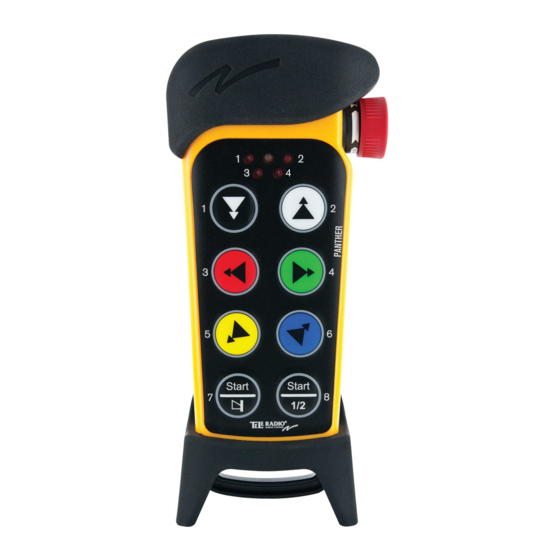
PN-TX-MX8B TRANSMITTER 1. Rubber cover 9. Button 3 2. Stop button 10. Button 5 3. LED 2 (red) 11. Button 7 - left start button 4. LED 4 (red) 12. Button 2 5. LED 1 (red) 13. Button 4 6. - Page 16 TRANSMITTER BACKSIDE 1. Rubber cover 2. Stop button 3. Battery pack - 14 -...
- Page 17 TECHNICAL DATA NO. OF BUTTONS PN-TX-MX8B 8 x 2-step buttons BATTERY PN-TX-MX8B 3 x 1.5V AAA/LR03 in battery pack D4-3 ON/OFF SWITCH PN-TX-MX8B DUPLEX COMMUNICATION PN-TX-MX8B SIZE PN-TX-MX8B 85 x 193 x 43 mm/3.4 x 7.7 x 1.7 in. ...
- Page 18 TRANSMITTER MEASUREMENTS 85 mm (3.4 in.) 43 mm (1.7 in.) - 16 -...
-
Page 19: Chapter 4: Installers Guide
Chapter 4: INSTALLERS GUIDE CHAPTER 4: INSTALLERS GUIDE DEFAULT RADIO MODE This transmitter is set to continuous radio mode by default. The transmitter starts to transmit continuously as soon as it has been started up. The radio transmission ends when the stop button is pressed. -
Page 20: Start The Transmitter
Chapter 4: INSTALLERS GUIDE START THE TRANSMITTER NOTE! Only for continuous radio mode. 1. Make sure that the stop button is pressed. 2. Twist and pull out the stop button. The top LED lights (green when the battery capacity is good, red when the battery capacity is poor), LEDs 3 + 4 flash (red). -
Page 21: Register The Transmitter In The Receiver
Chapter 4: INSTALLERS GUIDE 1. Radio mode 6. Logout 2. Replace 7. Shift button 3. Show channel Shift+3. Switch channel 4. Auto shutdown Shift+5. Load at start-up 5. Load select mode If no buttons are pressed within 1 minute, or if the stop button is pressed, the transmitter will turn off. ... - Page 22 Chapter 4: INSTALLERS GUIDE All relay LEDs light red. 7. Press transmitter button 1 and 2. Keep pressed. All relay LEDs light red. 8. The relay LEDs flash 2 times. 9. Release transmitter button 1 and 2. The relay LEDs flash 1 time. The transmitter is registered.
-
Page 23: Erase All Transmitters From The Receiver
ERASE ALL TRANSMITTERS FROM THE RECEIVER 1. Press the Function button in the receiver. The red function LED lights. 2. Press the receiver Select button. Keep pressed. All relay LEDs light red. 3. All relay LEDs go out. ... - Page 24 IMPORTANT! The replacement ID code is placed in the back of the transmitter. Remove the rubber cover. This label is placed above the battery lid. You will find the correct replacement ID code in the bottom of the replacement code label. 8.
-
Page 25: Frequencies And Channels
FREQUENCIES AND CHANNELS Channel Frequency 2405 MHz 2410 MHz 2415 MHz 2420 MHz 2425 MHz 2430 MHz 2435 MHz 2440 MHz 2445 MHz 2450 MHz 2455 MHz 2460 MHz 2465 MHz 2470 MHz 2475 MHz 2480 MHz ... - Page 26 Switch channel 1. Make sure that the stop button is pressed. 2. Press button 8. Keep pressed. 3. Twist and pull out the stop button. 4. Release button 8. Top LED flashes (green). 5. WITHIN 1 MINUTE FROM PULLING OUT THE STOP BUTTON: Enter the code: 1-2-3-4 (press the buttons 1, 2, 3, 4).
-
Page 27: Automatic Shutdown
AUTOMATIC SHUTDOWN NOTE! Only for continuous radio mode. Turning on automatic shutdown can save battery capacity by automatically turning the transmitter off when no function has been activated for a set time. Set the time for automatic shutdown ... -
Page 28: Logout
LOGOUT NOTE! Only for continuous radio mode. NOTE! Quick logout can only be made when the transmitter is on and the radio link is up. Quick logout 1. Press button 7. Keep pressed. 2. Press the stop button. ... -
Page 29: Relay Functionality
RELAY FUNCTIONALITY NOTE! If Operating mode 0 is selected, you can not make these settings. Contact your representative for assistance. NOTE! Momentary relay functionality is default. That means that the relay will only be activated when you press a button on the transmitter. When the button is released, the relay deactivates. Setting a relay to latching means that the relay gets activated every time that you press a button, but in this case the relay remains active until the button is pressed again. -
Page 30: Chapter 5: Operating Modes
Chapter 5: OPERATING MODES CHAPTER 5: OPERATING MODES SELECT OPERATING MODE NOTE! Go to the Operating modes pages to see what Operating modes that are available when transmitting in continuous/ discontinuous radio mode. Operating modes do not work for both radio modes. - Page 31 OPERATING MODE 1 NOTE! Only for continuous radio mode. step step step step 10 10 * Depending on transmitter Load select mode Button functions Direction functions On relays Relay 5 is active when radio link is up Work relays Recommended Load select mode 0, 1,3...
- Page 32 OPERATING MODE 2 NOTE! Only for continuous radio mode. step step step step * Depending on transmitter Load select mode Button functions Direction functions On relays Relay 5 is active when radio link is up Work relays Recommended Load select mode 0, 1, 3 Load select relays...
- Page 33 OPERATING MODE 3 NOTE! Only for continuous radio mode. step step step step 10 10 11 11 * Depending on transmitter Load select mode Button functions Direction functions On relays Relay 5 is active when radio link is up Work relays Recommended Load select mode 0, 1, 3...
- Page 34 OPERATING MODE 4 NOTE! Only for continuous radio mode. step step step step 10 10 1111 * Depending on transmitter Load select mode Button functions Direction functions On relays Relay 5 is active when radio link is up Work relays Recommended Load select mode 0, 1, 3...
- Page 35 OPERATING MODE 5 NOTE! Only for discontinuous radio mode. NOTE! Discontinuous radio mode cancels the PL d safety classified stop function. step step step step Button functions On relays Work relays Relay 5 is active when relay 1-4 or 6-11 is active Recommended Load select mode Load select relays Programmable settings...
-
Page 36: Chapter 6: Load Select Modes
Chapter 6: LOAD SELECT MODES CHAPTER 6: LOAD SELECT MODES MAKE A LOAD SELECTION NOTE! Only for continuous radio mode. NOTE! Load select mode 0 is default. 1. Make sure that the stop button is pressed. ... - Page 37 LOAD SELECT MODE 0-4 Load select mode 0 Load select mode 1 Load select mode 2 Load select mode 3 - 35 -...
- Page 38 Load select mode 4 - 36 -...
- Page 39 LOAD AT START-UP NOTE! We recommend starting with Load select before selecting load at start-up. 1. Make sure that the stop button is pressed. 2. Press button 8. Keep pressed. 3. Twist and pull out the stop button. ...
-
Page 40: Chapter 7: Battery Guide
Approx. 100 h. with alkaline (depending on D4-3 settings) CHARGE D4-2 Charge in the Tele Radio AB charger unit Do not charge in the Tele Radio AB charger unit. D4-3 Switch the batteries inside the battery pack. CHARGING TEMPERATURE D4-2 0-45°C/32-113°F... - Page 41 Switch batteries in the battery pack D4-3 WARNING! Do not charge the battery pack D4-3 in the Tele Radio AB charger unit or in any other way. NOTE! Electronics and batteries must be physically separated before disposal. Make sure that electronics or batteries are not thrown in the household waste.
- Page 42 The Tele Radio AB products are covered by a guarantee/warranty against material, construction and manufacturing faults. During the guarantee/warranty period, Tele Radio AB may replace the product or faulty parts. Work under guarantee/warranty must be carried out by Tele Radio AB or by an authorized service centre specified by Tele Radio AB.
-
Page 43: Chapter 8: Certifications Chapter
Chapter 8: CERTIFICATIONS CHAPTER CHAPTER 8: CERTIFICATIONS CHAPTER FCC STATEMENT Statement for warning: To satisfy FCC RF exposure requirements, a separation distance of 20 cm or more should be maintained between the antenna of this device and persons during device operation. To ensure compliance, operations at closer than this distance is not recommended. - Page 44 Chapter 8: CERTIFICATIONS CHAPTER Conformément à la réglementation d'Industrie Canada, le présent émetteur radio peut fonctionner avec une antenne d'un type et d'un gain maximal (ou inférieur) approuvé pour l'émetteur par Industrie Canada. Dans le but de réduire les risques de brouillage radioélectrique à l'intention des autres utilisateurs, il faut choisir le type d'antenne et son gain de sorte que la puissance isotrope rayonnée équivalente (p.i.r.e.) ne dépasse pas l'intensité...
- Page 45 EC/EEA DECLARATION OF CONFORMITY - 43 -...
- Page 46 ...
Need help?
Do you have a question about the PN-RX-MNB5 and is the answer not in the manual?
Questions and answers