
Related Manuals for Tele Radio TG-R10-1


Summary of Contents for Tele Radio TG-R10-1
- Page 1 End user instructions TG-T9-1 (TG-TX-MNL8), TG-T9-11 (TG-TX-MNR8), TG-T11-5 (TG-TX-MXL12),TG-T11-15 (TG-TX-MXR12), TG-R10-1 (TG-RX-MQL10B7), TG-R10-2 (TG-RX-MQL10A7) LANGUAGE: English (original) IM-TG2-ED003-A09-EN...
-
Page 2: Table Of Contents
CONTENTS Chapter 1: CUSTOMER INFORMATION 3 Chapter 2: END USER INSTRUCTIONS 5 TG-TX-MDL8, TG-TX-MDR8, TG-TX-MXL12, TG-TX-MXR12 transmitter 5 Product measurements 8 Start the transmitter in operating mode 9 Start the transmitter in operating mode with PIN codes 9 Turn the transmitter off 10 Login/logout 10 Replace 11 Automatic shutdown 12 Frequencies & channels 13 RoHS and WEEE 18 Guarantee, service, repairs and maintenance 19 Chapter 3: EC DECLARATION OF CONFORMITY 20 - 2 -... -
Page 3: Chapter 1: Customer Information
Chapter 1: CUSTOMER INFORMATION CHAPTER 1: CUSTOMER INFORMATION THANK YOU FOR PURCHASING A TELE RADIO AB PRODUCT READ ALL INSTRUCTIONS AND WARNINGS CAREFULLY BEFORE MOUNTING, INSTALLING AND CONFIGURATING THE PRODUCTS. These instructions are published by Tele Radio AB without any guarantee. The instructions may be removed or revised by Tele Radio AB at any time and without further notice. Corrections and additions will be added to the latest version of the instruction. IMPORTANT! These instructions are directed to installers. There are separate instructions directed towards end users. The instructions that contain information on the installation and configuration of the radio remote control unit on the machine are not intended to be passed on to the end user. Only such information may be passed on to the end user that is needed to operate the machine correctly by radio remote control. Tele Radio AB products are covered by a guarantee/ warranty against material, construction or manufacturing faults. During the guarantee/ warranty period, Tele Radio AB may replace the product or faulty parts with new. Work under guarantee/ warranty must be carried out by Tele Radio AB or by an authorized service center specified by Tele Radio AB. Contact your Tele Radio AB representative if you need support or service. ©Tele Radio AB Datavägen 21 SE-436 36 ASKIM... - Page 4 APPLICATION AREA FOR THE TIGER SYSTEM The Tele Radio AB Tiger remote control systems are aimed for remote controlling of lifting or mobile equipment where a high safety level is required. AUTHORIZATION BY PIN CODE To prevent from unauthorized users being able to start the transmitter and control the receiver, you can enable PIN codes for start-up protection. 1-6 PIN codes can be stored in the TG-TX- MNL8, TG-TX-MNR8, TG-TX-MXL12, TG-TX-MXR12 transmitters. PIN codes have to be set in the PC program Settings manager. STOP FUNCTION The transmitters have a stop button that controls the 2 stop relays in the receiver. 2 safety microcontrollers are supervising and controlling the stop relays. A valid signal must be provided from both microcontrollers to activate the stop relays. - 4 -...
-
Page 5: Chapter 2: End User Instructions
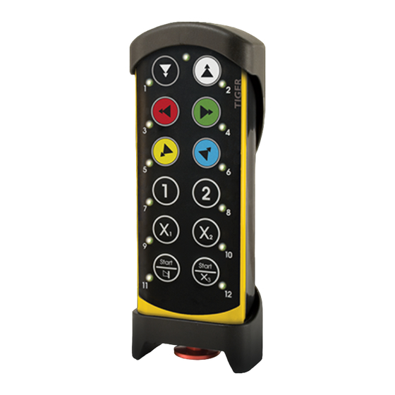
Chapter 2: END USER INSTRUCTIONS CHAPTER 2: END USER INSTRUCTIONS TG-TX-MDL8, TG-TX-MDR8, TG-TX-MXL12, TG-TX-MXR12 TRANSMITTER 1.Rubber cover 9. Button 6 2. Button 1 10. Button 8** 3. Button 3 11. Button LEDs 4. Button 5... - Page 6 TECHNICAL DATA NO. OF BUTTONS TG-TX-MNL8, TG-TX-MNR8 8 x 2-step buttons TG-TX-MXL12, TG-TX-MXR12 12 x 2-step buttons BATTERY TG-TX-MNL8, TG-TX-MNR8 Internal, rechargeable lithium-ion TG-TX-MXL12, TG-TX-MXR12 External, rechargeable lithium-ion ON/OFF SWITCH TG-TX-MNL8, TG-TX-MNR8 TG-TX-MXL12, TG-TX-MXR12 DUPLEX COMMUNICATION TG-TX-MNL8, TG-TX-MNR8, T G-TX-MDL10, Possible TG-TX-MXL12, TG-TX-MXR12 MAX. NO OF REGISTERED RECEIVERS TG-TX-MNL8, TG-TX-MNR8 TG-TX-MXL12, TG-TX-MXR12 SIZE TG-TX-MNL8, TG-TX-MNR8 160 x 76 x 37 mm./ 6.3 x 3 x 1.4 in. TG-TX-MXL12, TG-TX-MXR12 210 x 76 x 37 mm./ 8.2 x 3 x 1.4 in. WEIGHT TG-TX-MNL8, TG-TX-MNR8 295 g./ 0.6 lbs. TG-TX-MXL12, TG-TX-MXR12 400 g./ 0.9 lbs.
- Page 7 IP CLASS TG-TX-MNL8, TG-TX-MNR8, TG-TX-MXL12, TG-TX-MXR12 SENSITIVITY TG-TX-MNL8, TG-TX-MNR8, TG-TX-MXL12, Better than -110 dBm TG-TX-MXR12 OPERATING TEMPERATURE , T G-TX-MNL8, TG-TX-MNR8, T G-TX-MXL12, -20 - +55°C/ -4 - +130°F TG-TX-MXR12 NO. OF PIN CODES POSSIBLE TG-TX-MNL8, TG-TX-MNR8, T G-TX-MXL12, TG-TX-MXR12 RADIOTYPE TG-TX-MNL8, TG-TX-MNR8, TG-TX-MXL12, Low IF topology TG-TX-MXR12 ON/OFF SWITCH The TG-TX-MNL8, TG-TX-MNR8 transmitter has an on/off switch on the backside.The switch breaks the power supply from the battery. When in position 0/off, the transmitter cannot be started unless you connect the charger plug. When the transmitter is transported by airplane, the on/off switch ...
-
Page 8: Product Measurements
PRODUCT MEASUREMENTS TG-TX-MNL8,TG-TX-MNR8 76 mm (3 in) 46 mm (1.8 in) TG-TX-MXL12,TG-TX-MXR12 79 mm (3.1 in) 51 mm (2 in) 41 mm (1.6 in) - 8 -... -
Page 9: Start The Transmitter In Operating Mode
START THE TRANSMITTER IN OPERATING MODE 1. Make sure that the stop button is pressed. 2. Pull out the stop button. The top LED lights (green when the battery capacity is good, red when the battery capacity is poor). 3. If PIN codes are used for authorization: Go to the next section. 4. WITHIN 3 MINUTES F ROM PULLING OUT THE STOP BUTTON: Press a button to select the receiver(s) that you want to operate. The receiver(s) that was selected in the last session will be automatically selected, which is indicated by the corresponding LED(s) that light red. If no receiver(s) has been selected, the LEDs for all available receivers will flash red. If a receiver is selected, the LEDs next to the left and the right start buttons flash red. If no receiver(s) are selected, only the LED next to the right start button flashes red. 5. Press both start buttons at the same time. The buzzer beeps. 6. Release the start buttons. The buzzer stops beeping. The top LED flashes (green when the battery capacity is good, red when the battery capacity is poor). 7. When radio communication has been established, the top LED lights (green when the battery capacity is good, red when the battery capacity is poor). If r adio communication is not established within 25 seconds, the transmitter turns off. START THE TRANSMITTER IN OPERATING MODE WITH PIN CODES ... -
Page 10: Turn The Transmitter Off
Press a button to select the receiver(s) that you want to operate. The receiver(s) that was selected in the last session will be automatically selected, which is indicated by the corresponding LED(s) that light red. If no receiver(s) has been selected, the LEDs for all available receivers will flash red. If a receiver is selected, the LEDs next to the left and the right start buttons flash red. If no receiver(s) are selected, only the LED next to the right start button flashes red. 5. Press both start buttons at the same time.The buzzer beeps. 6. Release the start buttons. The buzzer stops beeping. The top LED flashes (green when the battery capacity is good, red when the battery capacity is poor). 7. When radio communication has been established, the top LED lights (green when the battery capacity is good, red when the battery capacity is poor). If r adio communication is not established within 25 seconds, the transmitter turns off. TURN THE TRANSMITTER OFF 1. Press the stop button. The transmitter turns off. All relays deactivate. LOGIN/LOGOUT NOTE! If you need to log out a transmitter that is lost or damaged, it is possible to log out from the receiver. We do not recommend this way of logging out. Contact your representative for assistance. NOTE! To be able to control a receiver, the transmitter must be registered in the receiver, and logged in to the receiver. If another transmitter is already logged in to the receiver, it has to be logged out before any other transmitter can be logged in. I f no transmitter is l ogged in to a receiver, a registered transmitter ... -
Page 11: Replace
REPLACE You can replace a registered transmitter with another transmitter without having access to the receiver. IMPORTANT! Do not perform this when the receiver is in a session with another transmitter. The radio communication may become disturbed or broken. IMPORTANT! If the transmitter that needs to be replaced is registered in more than one receiver, it will only be replaced in one receiver at a time. If you want to replace a transmitter in more than one receiver, you need to perform a replacement for each receiver. NOTE! If the new transmitter already has r eceivers registered, we recommend that you erase all receivers from the transmitter before starting the replacement. The receiver will a utomatically be stored in the same position as it was stored in the old transmitter. If this position is not available, the replacement will not take place. Replace a transmitter with a new transmitter 1. Make sure that the stop button is pressed. 2. Pull out the stop button. The top LED lights (green when the battery capacity is good, red when the battery capacity is poor). 3. Press the right start button. Keep pressed. 4. Press the stop button. 5. Release ... -
Page 12: Automatic Shutdown
AUTOMATIC SHUTDOWN Turning on automatic shutdown can save battery capacity by automatically turning the transmitter off when no function has been activated for a set time. Set the time for automatic shutdown 1. Make sure that the stop button is pressed. 2. Pull out the stop button. The top LED lights (green when the battery capacity is good, red when the battery capacity is poor). 3. Press the right start button. Keep pressed. 4. Press the stop button. 5. Release t he right start button. The top LED flashes (green when the battery capacity is good, red when the battery capacity is poor) when in menu mode. 6. Press button 5. 7. Press a button according to the table. PRESS BUTTON RESULTS IN The left start button auto shutdown off auto shutdown after 2 minutes auto shutdown after 6 minutes auto shutdown after 12 minutes... -
Page 13: Frequencies & Channels
FREQUENCIES & CHANNELS NOTE! If your system is transmitting on the frequency bands 433MHz eller 2.4 GHz, the receiver will automatically detect and switch to the same channel that the transmitter is using. If your system is transmitting the 915 MHz frequency band, you have to switch bank in the receiver by using the PC program Settings manager. Contact your representative for assistance. Switch channel on the transmitter 1. Make sure that the stop button is pressed. 2. Pull out the stop button. The top LED lights (green when the battery capacity is good, red when the battery capacity is poor). 3. Press the right start button. Keep pressed. 4. Press the stop button. 5. Release t he right start button. The top LED flashes (green when the battery capacity is good, red when the battery capacity is poor) when in menu mode. 6. Press the right start button. Keep pressed. 7. Press button 4. NOTE! Release button 4 before releasing the right start button. 8. Go to the frequency table and select a channel. 9. Enter a new channel with the buttons according to the table. The LED next to the left start button lights when a digit has been entered. If the channel that you have selected contains only one digit, press the left start button directly after entering the first digit. ... - Page 14 Frequency band 433MHz CHANNEL FREQUENCY CHANNEL FREQUENCY 433.075 433.950 433.100 433.975 433.125 434.000 433.150 434.025 433.175 434.050 433.200 434.075 433.225 434.100 433.250 434.125 433.275 434.150 433.300 434.175 433.325 434.200 433.350 434.225 433.375 434.250 433.400 434.275 433.425 434.300 433.450 434.325 433.475 434.350 433.500...
- Page 15 Frequency band 915 MHz Frequency-hopping spread spectrum (FHSS) is a method of transmitting radio signals by rapidly switching a carrier among many frequency channels, using a pseudorandom sequence known to both transmitter and receiver. For further information about the frequencies used in this frequency band and about frequency-hopping, please contact your representative. Frequency band 2.4 GHz CHANNEL FREQUENCY 2405 2410 2415 2420 2425 2430 2435 2440 2445 2450 2455 2460 2465 2470 2475 2480 - 15 -...
- Page 16 TRANSMITTER BACKSIDE TG-TX-MXL12 TG-TX-MXR12 TG-TX-MDL8 TG-TX-MDR8 1. Rubber cover 4. CE and product label 2. Stop button 5. Battery charger socket 3. Clip 6. On/off switch* *only on TG-TX-MNL8, TG-TX-MNR8 BATTERY INFORMATION IMPORTANT! Electronics and batteries must be physically separated before disposal. Make sure that electronics or batteries are not thrown in the household waste. IMPORTANT! For transmitters with an on/off switch, the switch must be in on position when charging. ...
- Page 17 Charge the battery 1.When approx. 10% of the battery capacity remains, the top LED lights red and the internal buzzer beeps 3 times. 2. Put the charger plug into the socket in the back of the transmitter. While charging, the top LED flashes red. 3.The external battery can also be charged in a Tele Radio AB charger unit . 4. When fully charged, the top LED lights green. - 17 -...
-
Page 18: Rohs And Weee
NOTE! For lithium-ion batteries, overcharging is not a problem. L ithium-ion batteries do not need to be fully discharged before being recharged. Charging the battery before fully discharged will not cause premature loss of function. Lithium- ion batteries are designed for operating environments from 0ºC to 60ºC/ 32ºF to 140ºF. Note that the environmental temperature and the operating temperature are not necessarily the same. The higher the temperatures, the faster the discharge. When you do not intend to use the transmitter for a longer period of time, we recommend that you remove the battery from the transmitter. The transmitter uses current even when being turned off. Leaving the battery in the transmitter may affect the battery life span. Improper long term storage of lithium-ion batteries can reduce their effective life. New lithium-ion batteries should be stored in a location with ambient temperatures between 20ºC to 38ºC/ 70º to 100ºF a t a 40% state of charge or lower. After use, batteries can be stored at higher charge levels. After a longer period of storage, we recommend recharging of batteries p rior to being placed back into service or use. Batteries stored in cold environments may need to be stabilized within normal temperature ranges prior to recharging and use. Batteries can be replaced when they are no longer capable of holding 80% of their original capacity. Users should consider how frequently an old battery is recharged compared to when it was new. We recommend that you check with your representative if you need further details. BATTERY PRECAUTIONS Observe the following general battery warnings: As batteries contains flammable substances such as lithium or other organic solvents, they may cause heating, rupture or ignition. Risk of explosion if battery is replaced with a battery of an incorrect type. Do not short circuit, disassemble, deform or heat batteries. Never try to charge a visibly damaged or frozen battery. Keep batteries out of reach of small children. Should a child swallow a battery, consult a physician immediately. Avoid direct soldering to batteries. When discarding batteries, insulate the + and - ... -
Page 19: Guarantee, Service, Repairs And Maintenance
1. Remove the clip. Remove the rubber cover by hand. Use a screwdriver to unscrew the 2 screws. 2. Use a screwdriver to unscrew the 4 screws. Remove the front encapsulation by hand. Turn the transmitter around, so that the buttons face up. 3. Use a screwdriver to unscrew the screw in the middle of the transmitter. Lift the circuit board up by hand. 4. The battery pack is placed behind the circuit board. Remove the battery by hand. GUARANTEE, SERVICE, REPAIRS AND MAINTENANCE The Tele Radio AB products are covered by a guarantee/warranty against material, construction and manufacturing faults. During the guarantee/warranty period, Tele Radio AB may replace the product or faulty parts. Work under guarantee/warranty must be carried out by Tele Radio AB or by an authorized service centre specified by Tele Radio AB. This is not covered by the guarantee/ warranty: Faults resulting from normal wear and tear Parts of a consumable nature Products that have been subject to unauthorized modifications Faults resulting from incorrect installation and use Damp and water damage Maintenance: Repairs and maintenance must be carried out by qualified personnel Use spare parts from Tele Radio AB only Contact your representative if you require service or other assistance ... -
Page 20: Chapter 3: Ec Declaration Of Conformity
Chapter 3: EC DECLARATION OF CONFORMITY CHAPTER 3: EC DECLARATION OF CONFORMITY - 20 -... - Page 21 Chapter 3: EC DECLARATION OF CONFORMITY - 21 -...
- Page 22 ...
Need help?
Do you have a question about the TG-R10-1 and is the answer not in the manual?
Questions and answers