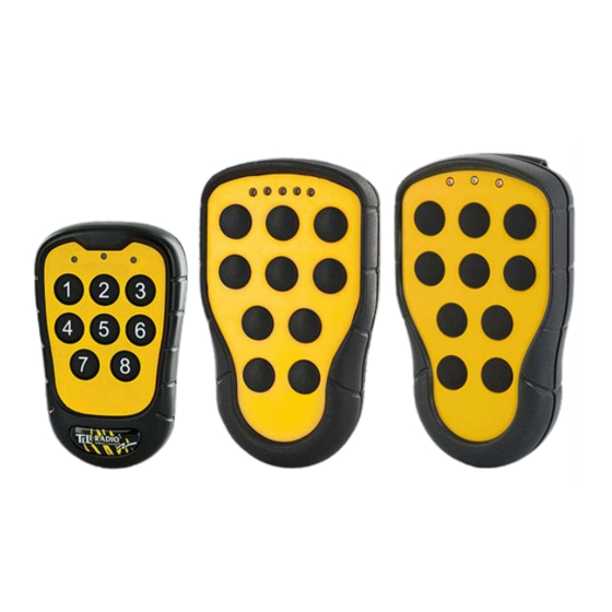
Tele Radio PN-RX-MN5 Installation Instructions Manual

Tele Radio PN-RX-MN5 Installation Instructions Manual

Industrial radio remote control

Advertisement

TELE RADIO


Installation instructions


PN-RX-MN5 (PN-R8-1), PN-RX-MD11 (PN-R8-6), PN-RX-MN5E (PN-R8-10),
PN-RX-MD11E (PN-R8-11), PN-TX-MD3M (PN-T13-3), PN-TX-MD6M (PN-T13-6),
PN-TX-MD8M (PN-T13-8), PN-TX-MD10M (PN-T13-10), PN-TX-MD3 (PN-T21-3),
PN-TX-MD6 (PN-T21-6), PN-TX-MD8 (PN-T21-8), PN-TX-MD10 (PN-T21-10),
PN-TX-MN3 (PN-T7-16), PN-TX-MN6 (PN-T7-15), PN-TX-MN8 (PN-T7-14)


IM-PN-RX010-A04-EN
PANTHER
Language: English (original)


Advertisement

Table of Contents
loading
Need help?

Need help?

Do you have a question about the PN-RX-MN5 and is the answer not in the manual?

Questions and answers

Summary of Contents for Tele Radio PN-RX-MN5

  • Page 1: Installation Instructions

    Installation instructions           PN-RX-MN5 (PN-R8-1), PN-RX-MD11 (PN-R8-6), PN-RX-MN5E (PN-R8-10), PN-RX-MD11E (PN-R8-11), PN-TX-MD3M (PN-T13-3), PN-TX-MD6M (PN-T13-6), PN-TX-MD8M (PN-T13-8), PN-TX-MD10M (PN-T13-10), PN-TX-MD3 (PN-T21-3), PN-TX-MD6 (PN-T21-6), PN-TX-MD8 (PN-T21-8), PN-TX-MD10 (PN-T21-10), PN-TX-MN3 (PN-T7-16), PN-TX-MN6 (PN-T7-15), PN-TX-MN8 (PN-T7-14)   Language: English (original)  ...
  • Page 2: Table Of Contents

    CONTENTS Chapter 1: CUSTOMER INFORMATION Chapter 2: PRODUCT PAGES PN-RX-MN5, PN-RX-MN5E Base board receiver PN-RX-MD11, PN-RX-MD11E Base board receiver with a Relay expansion board PN-TX-MD, PN-TX-MDM, PN-TX-MN Transmitters Chapter 3: INSTALLERS GUIDE Default radio mode Start the transmitter Register the transmitter in the receiver...
  • Page 3: Chapter 1: Customer Information

    During the guarantee/ warranty period, Tele Radio AB may replace the product or faulty parts with new. Work under guarantee/ warranty must be carried out by Tele Radio AB or by an authorized service center specified by Tele Radio AB. Contact your Tele Radio AB representative if you need support or service.
  • Page 4 Chapter 1: CUSTOMER INFORMATION WARNINGS & RESTRICTIONS   WARNING! Tele Radio remote controls are often built into wider applications. We recommend that the system is provided with a wired emergency stop where necessary.   INSTALLING, CONNECTING AND MOUNTING   Allow only licensed or qualified personnel to install the product.
  • Page 5: Chapter 2: Product Pages

    Chapter 2: PRODUCT PAGES CHAPTER 2: PRODUCT PAGES   PN-RX-MN5, PN-RX-MN5E BASE BOARD RECEIVER   WARNING! The receiver must NOT be opened by any other than a qualified installer. Make sure to turn the electricity off before opening the receiver.
  • Page 6 FUNCTION LEDS INDICATION IN OPERATING MODE   Function LED Off On Indicates   No transmitter is registered. Flashes once: One or more transmitters are registered. No radio transmission   established. 7 (red) Double flash: One or more transmitters are registered and logged in. No radio  ...
  • Page 7: Pn-Rx-Md11, Pn-Rx-Md11E Base Board Receiver With Arelay Expansion Board

    PN-RX-MD11, PN-RX-MD11E BASE BOARD RECEIVER WITH A RELAY EXPANSION BOARD   WARNING! The receiver must NOT be opened by any other than a qualified installer. Make sure to turn the electricity off before opening the receiver.   Base board:   1.
  • Page 8 Relay expansion board:   10. Function relays 6-11 12. Communication LED (green) 11. Relay LEDs 6-11 (red) 13. Programming connector     TERMINAL BLOCK FOR INPUT POWER ON BASE BOARD     1. 12 - 24V DC 2. Negative terminal DC voltage  ...
  • Page 9 10 (orange) 2. Load select mode is activated. Incorrect Load is selected on the transmitter.     TECHNICAL DATA   PN-RX-MN5, PN-RX-MN5E: 5 Number of function relays PN-RX-MD11, PN-RX-MD11E: 11 (potential free*, 10A, 250V AC) Input power 12-24V DC Digital inputs Duplex communication Max.
  • Page 10 CURRENT CONSUMPTION   Input power Min.* Max.** 12V DC 0.02A 0.3A 24V DC 0.02A 0.2A 24V AC 0.02A 0.2A 48V AC 0.01A 0.05A 110V AC 0.005A 0.03A 230V AC 0.01A 0.02A *Minimum current consumption= Receiver powered, no radio session established, nothing else activated on the receiver.
  • Page 11 RECEIVER MEASUREMENTS   120.5 mm. (4.744 in.) 102 mm. (4.016 in.) - 11 -...
  • Page 12: Pn-Tx-Md, Pn-Tx-Mdm, Pn-Tx-Mn Transmitters

    PN-TX-MD, PN-TX-MDM, PN-TX-MN TRANSMITTERS     PN-TX-MD PN-TX-MDM PN-TX-MN 1. LED 1 (red) 1. LED 1 (red) 1. LED 1 (red) 2. LED 2 (red) 2. Top LED (red, green) 2. Top LED (red, green) 3. Top LED (red, green) 3.
  • Page 13 TRANSMITTER BACKSIDE   PN-TX-MD PN-TX-MDM PN-TX-MN 1. On/Off switch 1. On/off switch 1. On/off switch 2. Clip 2. Clip 2. Clip 3. CE/FCC/IC label 3. CE/FCC/IC label 3. CE/FCC/IC label       ON/OFF SWITCH   The transmitter has an on/off switch on the backside.
  • Page 14 TECHNICAL DATA   NO. OF BUTTONS PN-TX-MD3, PN-TX-MD3M, PN-TX-MN3 3 x 1-step button PN-TX-MD6, PN-TX-MD6M, PN-TX-MN6 6 x 1-step button PN-TX-MD8, PN-TX-MD8M, PN-TX-MN8 8 x 1-step button PN-TX-MD10, PN-TX-MD10M 10 x 1-step button   BATTERY PN-TX-MD 3 x 1.5V AAA PN-TX-MDM, PN-TX-MN 2 x 1.5V AAA  ...
  • Page 15: Chapter 3: Installers Guide

    Chapter 3: INSTALLERS GUIDE CHAPTER 3: INSTALLERS GUIDE   DEFAULT RADIO MODE   The transmitter is set to discontinuous radio mode by default. To establish a radio link between the transmitter and the receiver, both need to be in the same radio mode.  ...
  • Page 16: Erase All Transmitters From The Receiver

    Chapter 3: INSTALLERS GUIDE ERASE ALL TRANSMITTERS FROM THE RECEIVER    1. Press the Function button on the receiver. Function LED lights red.  2. Press the Select button on the receiver. All relay LEDs light red.  3. All relay LEDs go out.  4.
  • Page 17: Logout

    Chapter 3: INSTALLERS GUIDE Switch channel   NOTE! Only for the PN-TX-MD and when in continuous radio mode.    1. Start the transmitter. The top LED flashes green.  2. Press the Off-button on the transmitter. Keep pressed. The top LED flashes red.  3.
  • Page 18: Make A Load Selection

    Chapter 3: INSTALLERS GUIDE AUTOMATIC SHUTDOWN   NOTE! You can not change the automatic shutdown time from the transmitter. Contact your representative for assistance.   The transmitter automatic shutdown time is set to 3 minutes by default.     MAKE A LOAD SELECTION  ...
  • Page 19: Operating Mode 1

    OPERATING MODE 1     Button functions   On relay Working relay Relay 11 is active when relay 1-10 is active Recommended Load Selection mode Programmable settings Relay 1-10 can be set latching Interlocking Radio mode Discontinuous Zero position check - 19 -...
  • Page 20: Chapter 4: Battery Guide

    Chapter 4: BATTERY GUIDE CHAPTER 4: BATTERY GUIDE   BATTERY INFORMATION   WARNING! Do not recharge the batteries. Attempts to recharge may cause rupture or the leaking of hazardous liquids, which will corrode the equipment.   NOTE! Electronics and batteries must be physically separated before disposal. Make sure that electronics or batteries are not thrown in the household waste.
  • Page 21 The Tele Radio AB products are covered by a guarantee/warranty against material, construction and manufacturing faults. During the guarantee/warranty period, Tele Radio AB may replace the product or faulty parts. Work under guarantee/warranty must be carried out by Tele Radio AB or by an authorized service centre specified by Tele Radio AB.
  • Page 22: Chapter 5: Certifications Chapter

    Chapter 5: CERTIFICATIONS CHAPTER CHAPTER 5: CERTIFICATIONS CHAPTER   FCC STATEMENT   Statement for warning:   Caution: The user is cautioned that changes or modifications not expressly approved by the party responsible for compliance could void the user's authority to operate the equipment. This device complies with Industry Canada licence-exempt RSS standard(s) and Part 15 of the FCC Rules.
  • Page 23 Under Industry Canada regulations, this radio transmitter may only operate using an antenna of a type and maximum (or lesser) gain approved for the transmitter by Industry Canada. To reduce potential radio interference to other users, th antenna type and its gain should be so chosen that the equivalent isotropically radiated power (e.i.r.p.) is not more than that necessary for successful communication.
  • Page 24 EC/EEA DECLARATION OF CONFORMITY     - 24 -...
  • Page 25 - 25 -...
  • Page 26               - 26 -...
  • Page 27         (THIS PAGE IS INTENTIONALLY LEFT BLANK) - 27 -...
  • Page 28  ...

Table of Contents