
Subscribe to Our Youtube Channel
Related Manuals for ADRF PSR-VU-9537-UB


Summary of Contents for ADRF PSR-VU-9537-UB
- Page 1 PSR-VU-9537-UB Manual Version 0.1 3116 West Vanowen St. Burbank, CA 91505 Tel: 818-840-8131 Fax: 818-840-8138 www.adrftech.com Advanced RF Technologies, Inc.
- Page 2 Information in this document is subject to change without notice. Advanced RF Technologies, Inc. 1996-2015. All rights reserved. Please send comments to: E-Mail: info@adrftech.com Phone: (818) 840-8131 (800) 313-9345 Fax: (818) 840-8138 Address: Advanced RF Technologies, Inc. Attention: Technical Publications Department 3116 Vanowen St.
- Page 3 Revision History Version Author Descriptions Date YH Ko Initial Release 29/10/20 Change List Version Change list Contents Advanced RF Technologies, Inc.
-
Page 4: Table Of Contents
Installation Procedures ..........................26 5.1.1 Wall Mount Procedure ........................26 5.1.2 PSR-ANN Annunciator Installation ..................... 26 Antenna Separation/Isolation ........................28 ADRF-BBL/BBS-U Installation ..........................30 Installation Procedures ..........................30 PSR-VU-9537-UBWeb-GUI Setup introduction ....................35 Repeater/PC Connection Using Web-GUI ....................36 Status Tab ..............................37 7.2.1 Band Info ............................ - Page 5 10.1 Mechanical Specifications.......................... 53 10.2 Power Specifications ..........................54 10.3 ADRF-BBS-U-24 / ADRF-BBL-U-24 Runtime Calculations ................55 PSR-VU-9537-UB(Dual Band) w/ (1) ADRF-BBL-U-24(2 serial connection for 48V) ............. 55 10.4 Warranty & Certificates ..........................55 Mechanical Drawing ............................56 Advanced RF Technologies, Inc.
- Page 6 Appendix ................................60 12.1 Shutdown Retry Logic ..........................60 Figures Figure 1-1 PSR-VU-9537-UBRepeater Parts List ....................10 Figure 1-2 PSR-VU-9537-UBQuick View (front and bottom) ................11 Figure 1-3 PSR-ANN Annunciator ........................12 Figure 2-1 AC 100-240V Terminal Block ......................17 Figure 3-1 LED Panel ............................
- Page 7 Figure 11-3 ADRF-BBL-U Mechanical Drawing....................... 58 Figure 11-4 ADRF-BBS-U Mechanical Drawing ...................... 59 Advanced RF Technologies, Inc.
- Page 8 Terms and Abbreviations The following is a list of abbreviations and terms used throughout this document. Abbreviation/Term Definition Automatic Gain Control Automatic Level Control ADRF’ Repeater Operation and Management System AROMS Band Combiner Unit Base Transceiver Station Bi-directional Amplifier CDMA...
-
Page 9: Introduction
RF shadow environments. This unit feature low noise figure and wide dynamic range and are certified to UL 2524. PSR-VU-9537-UB is a revolutionary digital public safety repeater designed to protect the lives of first responders and building occupants. ... -
Page 10: Parts List
1.4 Parts List Table 1-1 Message Board Alarms and Notifications Label Quantity Description PSR-VU-9537-UA Wall Mount Bracket Mounting Bracket Template AAI Alarm Cable Ethernet Cable (Crossover) Anchor Bolt PSR-ANN (Annunciator Box) Figure 1-1 PSR-VU-9537-UBRepeater Parts List Advanced RF Technologies, Inc. -
Page 11: Quick View
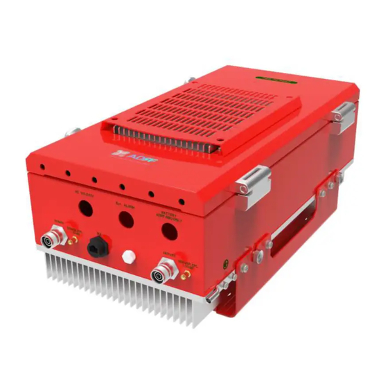
DONOR_CPL SERVER CPL (-30dB) (-30dB) Ext. ALARM Monitor Port, -30dB) Ethernet Port AAI Alarm Port AC 100-240V BATTERY ADRF-BBU ONLY Battery Backup AC Input Port ANNUNCIATOR Port +54V / 1A Max. NON LPS Annunciator Communication / Power Port Figure 1-2 PSR-VU-9537-UBQuick View (front and bottom) Advanced RF Technologies, Inc. -
Page 12: Figure 1-3 Psr-Ann Annunciator
Audible Alarm Speaker Alarm Indicator Lights Data/Power Port Repeater / Wall Mount Bracket Figure 1-3 PSR-ANN Annunciator Advanced RF Technologies, Inc. -
Page 13: Warnings And Hazards
In accordance with the FCC regulations (90.219), this device must meet 5W ERP requirements. WARRANTY Opening or tampering the PSR-VU-9537-UB will void all warranties. Lithium Battery: CAUTION. RISK OF EXPLOSION IF BATTERY IS REPLACED BY INCORRECT TYPE. DISPOSE OF USED BATTERIES ACCORDING TO INSTRUCTIONS. - Page 14 Use of unauthorized antennas, cables, and/or coupling devices not conforming with ERP/EIRP is prohibited. FCC Part 15.21 Any changes or modifications not expressly approved by the party responsible for compliance could void the user's authority to operate this equipment. FCC Part 15 Class A NOTE: This equipment has been tested and found to comply with the limits for a Class A digital device, pursuant to part 15 of the FCC Rules.
- Page 15 RSS-GEN, (6.8 Transmit antenna) Under Industry Canada regulations, this radio transmitter may only operate using an antenna of a type and maximum (or lesser) gain approved for the transmitter by Industry Canada. To reduce potential radio interference to other users, the antenna type and its gain should be so chosen that the equivalent isotropically radiated power (e.i.r.p.) is not more than that necessary for successful communication.
-
Page 16: Installation
Table 2-1 Pre-cut hole size and labels Silkscreen Label Location Diameter AC 100-240V LEFT 22.2mm (7/8”) ANNUNCIATOR RIGHT 22.2mm (7/8”) BATTERY ADRF-BBU ONLY NON LPS RIGHT 22.2mm (7/8”) DONOR1 BOTTOM 33.0mm (1-3/8”) DONOR2 BOTTOM 33.0mm (1-3/8”) Ext. ALARM BOTTOM 33.0mm (1-3/8”) -
Page 17: Wire Terminals
2.2 Wire Terminals Non-power limited cables such as the AC power line and the DC battery line shown below in red must be separated by ¼” from power limited cables such as the donor/server, ext. alarm, and annunciator lines shown below in black. -
Page 18: Overview
Table 2-2 Terminal Block Definition Silkscreen Label Line Type Max Supported AWG AC_NU Neutral 12AWG AC_R Line or Hot 12AWG AC_G Ground 12AWG 3. OVERVIEW PSR-VU-9537-UBLED indicator lights are located on the inside of the repeater towards the bottom. Below the LED indicators is a button that is used to trigger the door open alarm. -
Page 19: Cable Connection
Cable Connection 3.2.1 AC Power The AC Terminal is located at the bottom of the wiring compartment on the opposite side of the wiring compartment door. The repeater and has a free-voltage range input of 100-240V AC. The AC terminal box can support a max gauge of 12AWG and should be connected to the breaker box on its own circuit. -
Page 20: External Alarm
This port should be connected only to the fire alarm control panel. The default length of the cable that is provided to connect to an FACP is 6m (19.5ft). The EXT alarm wiring cannot exceed 30m (98.5ft). Table 3-2 External Alarm Port Pin Description ADRF External Alarm Box Alarm Color Pin Description (24 pins) -
Page 21: Annunciator
3.2.3 RF DL DONOR UL DONOR DL SERVER UL SERVER DONOR SERVER MODEM_ANT DONOR_CPL SERVER CPL (-30dB) (-30dB) Ext. ALARM The RF connections are made via two 4.3-10 female connectors. The RF connector labeled “DL DONOR1”, “UL DONOR” and “DONOR” must be connected to the antenna pointing towards the base station. The RF connection labeled “DL SERVER”, “UL SERVER”... -
Page 22: Battery Backup Terminal
Battery Backup Port (4-pin Female) When the ADRF-BBS/BBL-24 is connected to the repeater, the battery switch on the PSU must be switched to the ON position. This will enable the repeater to charge the ADRF-BBS/BBL-24 battery backup unit when AC power is present. -
Page 23: Grounding
(WARNING: The circuit breaker switch on the ADRF-BBS/BBL-24 must be set to OFF before connecting it to the PSR-VU-9537-UBto prevent damage to the repeater or the ADRF-BBS/BBL-24 and personal injury.) Note: Please contact ADRF Technical Support for assistance if you are unfamiliar with the installation procedure of the battery box. -
Page 24: Alarms
4. ALARMS 4.1 Message Board Alarms and Notifications Table 4-1 Message Board Alarms and Notifications Alarm Alarm Description Trigger Condition AC Input is outside of AC Fail The power supply is not operating within specs. (4 seconds) operating range DC Output is outside of DC Fail The power supply is not operating within specs. -
Page 25: External Alarm Output Interface
4.2.1 External Alarm Output interface 24V DC FACP Digital Board ADRF Digital Board ADRF PSR Repeater Fire Alarm Control Panel External Alarm Name Set Condition Likely Causes Donor Antenna Malfunction UL Return Power Hard Fail Damaged Donor Antenna RF Power Soft Fail... -
Page 26: Repeater Installation
5. REPEATER INSTALLATION Installation Procedures 5.1.1 Wall Mount Procedure Verify that the PSR-VU-9537-UBand mounting holes are in good condition Place the PSR-VU-9537-UBmounting bracket template up against the wall and mark off mounting holes Drill the appropriate size holes and install the included wall anchors ... -
Page 27: Figure 5-2 Psr-Ann Repeater Mount
Figure 5-2 PSR-ANN Repeater Mount Advanced RF Technologies, Inc. -
Page 28: Antenna Separation/Isolation
Figure 5-3 PSR-ANN Wall Mount Antenna Separation/Isolation The separation between the donor and server antennas is necessary to prevent oscillation. Oscillation occurs when the signal entering the system continually re-enters, due to the lack of separation between the donor and server antennas. -
Page 29: Figure 5-4 Rf Repeater Oscillation
Figure 5-4 RF Repeater Oscillation To prevent feedback, the donor and server antennas must be separated by an appropriate distance to provide sufficient isolation. Isolation can be attained by separating antennas at a sufficient distance so that the output of one antenna does not reach the input of the other. This distance is dependent on the gain of the repeater. Recommended isolation value is 15dB greater than the user-set gain of the repeater. -
Page 30: Adrf-Bbl/Bbs-U Installation
24VDC. The battery charger is built into the PSU located inside of the PSR-VU-9537-UA. When the system is being powered by AC, the PSU will charge the ADRF-BBL/BBS-U battery backup. When there is a loss of primary power (AC), then repeater will switch over to the secondary power (DC) provided by the battery backup. - Page 31 3. Move the ADRF-BBL-U-24 to the desired location and spin the red dial to the right to tighten wheel locks. 4. The brackets on the back of the ADRF-BBL/BBS-U unit can be used to secure to the wall ONLY when it is stationed on the floor.
- Page 32 7. On the PSR-VU-9537-UA, verify that both AC and BATT switches have been set to the OFF position. 8. Use the provided battery backup cable from the ADRF-BBL-U and connect the wires to the terminal block located inside of the wiring compartment of the PSR-VU-9537-UA.
- Page 33 10. Install a conduit hub connector that can support 7/8” onto the ADRF-BBL-U hole labeled BATTERY. 11. Open the wiring compartment of the ADRF-BBL-U and wire the battery cable to the terminal block. 12. On the PSR-VU-9537-UA, wire the AC terminal block to your dedicated circuit breaker...
- Page 34 13. On the PSR-VU-9537-UA, flip the POWER and BATT switch to the ON position. 14. On the ADRF-BBL-U-24, set the circuit breaker to the ON position. Advanced RF Technologies, Inc.
-
Page 35: Psr-Vu-9537-Ubweb-Gui Setup Introduction
PSR-VU-9537-UBWEB-GUI SETUP INTRODUCTION The Web-GUI allows the user to communicate with the repeater locally. To connect to the repeater locally, you will need a laptop with an Ethernet port and an RJ-45 crossover cable. NOTICE TO USERS, INSTALLERS, AUTHORITIES HAVING JURISDICTION, AND OTHER INVOLVED PARTIES This product incorporates field-programmable software. -
Page 36: Repeater/Pc Connection Using Web-Gui
If you are not the Administrator, please type in your assigned username & password which you should have received from the Administrator. The default username and password for the General User is adrf & adrf, respectively. The default Administrator login is admin & admin, respectively. -
Page 37: Status Tab
Status Tab Figure 7-3 Status Tab Advanced RF Technologies, Inc. -
Page 38: Band Info
7.2.1 Band Info The Band Info section displays frequency information along with the corresponding bandwidths that have been set from the Install tab. Input levels for each channel are also displayed in this section. Status Tab – Band Info Display Figure 7-4 7.2.2 Power &... -
Page 39: Alarms
7.2.3 Alarms This section displays the alarm status for System alarms, RF Alarms, and Power alarms. If an alarm is present in the system, then the color of the alarm tab will change according to the type of failure. Status Tab – Alarm Display Figure 7-6 7.2.4 AAI ... -
Page 40: Repeater Info / Repeater Location / Technical Support / Installer Contact Info
Repeater Info: Displays the serial number, latitude, longitude, firmware version, and Web-GUI version Repeater Location: Displays the address where the repeater is installed Technical Support: Displays ADRF’s Technical Support contact information Installer Contact Info: Displays the installer’s name, phone, and e-mail address... -
Page 41: Control Tab
Control Tab Figure 7-9 Control Tab Advanced RF Technologies, Inc. -
Page 42: General Settings
7.3.1 General Settings The General Settings section allows the user to enable/disable amplifiers and the ALC routine. Figure 7-10 Control Tab – General Setting ALC ON: Enables or disables Automatic Level Control (ALC) DL HPA On: Enables or disables the Downlink High Power Amplifier ... -
Page 43: Alarm Settings & Battery Alarm Settings
7.3.4 Alarm Settings & Battery Alarm Settings Figure 7-13 Control Tab – Alarm & Battery Alarm Settings DL Signal Low Level: Allows the user to specify how low the signal can be before triggering a “Downlink Signal Low” soft-fail alarm ... -
Page 44: Install Tab
Install Tab Figure 7-15 Install Tab 7.4.1 Technology This section allows the user to set the repeater mode to either use VHF, APCO25, or LMR450. Advanced RF Technologies, Inc. -
Page 45: Figure 7-16 Install Tab - Technology
Figure 7-16 Install Tab – Technology The following choices are available from the drop-down menu: VHF(136-174MHz) APCO25(380-470MHz) LMR450(450-512MHz) Advanced RF Technologies, Inc. -
Page 46: Band Selection
7.4.2 Band Selection Figure 7-17 Install Tab – Band Selection Band selection allows the user to specify the desired frequencies by inputting the center frequencies and selecting the bandwidths. Channel Center Frequency: The user can input the center frequency of the pass-band. ... -
Page 47: Date & Time
Figure 7-19 Install Tab – Location Info / Installer Info 7.4.5 Date & Time This section allows the user to specify the current date and time. Figure 7-20 Install Tab – Date & Time Advanced RF Technologies, Inc. -
Page 48: System
System The System tab allows the user to perform firmware updates, upload closeout packages, view any changes to the system, backup existing configuration, add/remove user accounts, and change the login credentials of the Administrator. 7.5.1 System: Account 7.5.1.1 System: Account – Account Management The Account Management section allows the Administrator to delete any user accounts. -
Page 49: System - Logs
7.5.2 System – Logs This section displays system events that have taken place. The Log displays the time and date of when the event took place, and what changes were made to the system. Figure 7-24 System: Logs 7.5.3 System – Update ... -
Page 50: System - Backup / Restore
Once the firmware update is complete, the following popup message will appear: Figure 7-26 System: Update is Complete Popup Message 7.5.4 System – Backup / Restore The Backup / Restore section allows the user to save the settings of the repeater. To perform the backup, click on the Backup button and you will be prompted to save the backup file. -
Page 51: Help
Turn the circuit breaker to the off position and unscrew the fuse holder to inspect the fuse i. A spare fuse is included with the purchase of the ADRF-BBL-U and can be used to replace the fuse if needed ... -
Page 52: Preventive Measures For Optimal Operation
Preventive Measures for Optimal Operation 8.2.1 Recommendations Perform the Periodic Inspection Checklist on a semi-annually basis. 8.2.2 Precautions Do not operate the repeater with the antennas in extremely close proximity to one another as this may cause damage to the repeater. ... -
Page 53: Specifications
10. SPECIFICATIONS Specification Parameters Remarks FCC: 150~174 (24) Frequency Range IC: 138~144 (6), 148~174 (26) (Nominal Bandwidth) FCC: 406.1~470 (64.1), 470~512 (42) (MHz) IC: 406.1~430 (24.1), 450~470(20) 28 dBm 24 dBm Composite Output Power 37 dBm 27 dBm 28 dBm 24 dBm Rated Mean... -
Page 54: Power Specifications
28VDC Nominal, 108.3mA AC Supply Protection Fuse & Circuit Protector T6.3L250V Ground External Threaded Stud Battery Type Valve Regulated, Sealed Lead Acid Rechargeable Battery ADRF-BBL-U-24: Tempest TR120-12 Battery Model ADRF-BBS-U-24: Tempest TR45-12 TR120-12: 120Ah Battery Capacity TR45-12: 48Ah Maximum Current Charge ... -
Page 55: Adrf-Bbs-U-24 / Adrf-Bbl-U-24 Runtime Calculations
10.3 ADRF-BBS-U-24 / ADRF-BBL-U-24 Runtime Calculations PSR-VU-9537-UBw/ ADRF-BBL/BBS-U-24(Two BBU serial connection) Battery Runtime Calculations PSR-VU-9537-UB(Dual Band) w/ ADRF-BBL-U-24(2 serial connection for 48V) Repeater DC Power Consumption (W) – 175.2 DC Voltage (V) – 48 DC Current Draw (A) – 3.65 ... -
Page 56: Mechanical Drawing
11. MECHANICAL DRAWING Figure 11-1 PSR-VU-9537-UBMechanical Drawing Advanced RF Technologies, Inc. -
Page 57: Figure 11-2 Psr-Ann Annunciator Mechanical Drawing
Figure 11-2 PSR-ANN Annunciator Mechanical Drawing Advanced RF Technologies, Inc. - Page 58 Figure 11-3 ADRF-BBL-U Mechanical Drawing Advanced RF Technologies, Inc.
- Page 59 Figure 11-4 ADRF-BBS-U Mechanical Drawing Advanced RF Technologies, Inc.
-
Page 60: Appendix
12. APPENDIX 12.1 Shutdown Retry Logic The function of the built-in shutdown routine is to protect the repeater from any further damage from a hard- fail that the system may be experiencing. Within 5 seconds of a hard-fail alarm being detected, the repeater will start the shutdown routine. The repeater will shut down by powering off the HPAs (high-powered amplifiers) for 30 seconds.
Need help?
Do you have a question about the PSR-VU-9537-UB and is the answer not in the manual?
Questions and answers