
Related Manuals for ADRF FiRe-78-4


Summary of Contents for ADRF FiRe-78-4
- Page 1 FiRe-78-4 Installation and Operating Manual Version 0.2 3116 West Vanowen St. Burbank, CA 91505 Tel: 818-840-8131 Fax: 818-840-8138 www.adrftech.com Advanced RF Technologies, Inc.
- Page 2 Information in this document is subject to change without notice. Advanced RF Technologies, Inc. 1996-2015. All rights reserved. • Please send comments to: E-Mail: info@adrftech.com Phone: (818) 840-8131 (800) 313-9345 Fax: (818) 840-8138 • Address: Advanced RF Technologies, Inc. Attention: Technical Publications Department 3116 Vanowen St.
- Page 3 Revision History Version Author Descriptions Date YH Ko Initial Release 2017/11/17 CK CHO Update 2018/01/09 Change List Version Change list Contents Advanced RF Technologies, Inc.
-
Page 4: Table Of Contents
..............................17 Specifications ..............................17 Electrical Specifications ..........................18 Mechanical Specifications.......................... 19 Figures Figure 1-1 FiRe-78-4 Quick View (front and bottom) .................... 7 Figure 2-1 FiRe-78-4 DAS topology ........................12 Figure 3-1 AC Power port............................. 12 Figure 3-2 External Alarm port .......................... - Page 5 The following is a list of abbreviations and terms used throughout this document. Abbreviation/Term Definition Automatic Gain Control Automatic Level Control AROMS ADRF’ Repeater Operation and Management System Band Combiner Unit Base Transceiver Station Bi-directional Amplifier CDMA Code Division Multiple Access...
-
Page 6: Introduction
1. INTRODUCTION FiRe-78-4 which is the wireless Head end of Distributed Antenna System for VHF/UHF band has roles which interfaces with Base Station via wireless and optically distributes by connection with multiple ADXV-R-3378P-N4X, which is one of the ADRF’s DAS product lineups, via optic lines. -
Page 7: Quick View
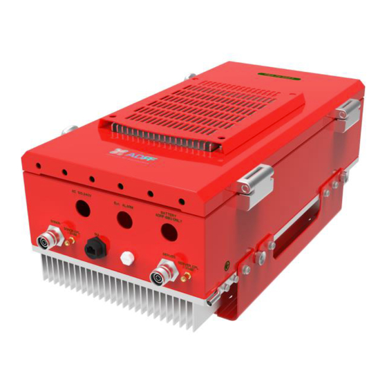
1.2 Quick View Figure 1-1 FiRe-78-4 Quick View (front and bottom) Advanced RF Technologies, Inc. -
Page 8: Warnings And Hazards
1.3 Warnings and Hazards WARNING! ELECTRIC SHOCK Opening the PSR-VU-9537 could result in electric shock and may cause severe injury. WARNING! EXPOSURE TO RF Working with the PSR-VU-9537 while in operation, may expose the technician to RF electromagnetic fields that exceed FCC rules for human exposure. Visit the FCC website at www.fcc.gov/oet/rfsafety to learn more about the effects of exposure to RF electromagnetic fields. - Page 9 Lithium Battery: CAUTION. RISK OF EXPLOSION IF BATTERY IS REPLACED BY INCORRECT TYPE. DISPOSE OF USED BATTERIES ACCORDING TO INSTRUCTIONS. Preclude indications that Home/ personal use are prohibited. Use of unauthorized antennas, cables, and/or coupling devices not conforming with ERP/EIRP is prohibited.
- Page 10 Part 90.635 requirement Antennas must be installed in accordance with FCC 90.635. With 17 dBi gain antennas the height of the antenna above average terrain (HAAT) must not exceed 85 m. For different gain antennas refer to the relevant rules. WARRANTY This is NOT a CONSUMER device.
- Page 11 RSS-GEN, Sec. 7.1.2– (detachable antennas) This radio transmitter (identify the device by certification number, or model number if Category II)has been approved by Industry Canada to operate with the antenna types listed below with the maximum permissible gain and required antenna impedance for each antenna type indicated. Antenna types not included in this list, having a gain greater than the maximum gain indicated for that type, are strictly prohibited for use with this device.
-
Page 12: Topology
AC IN EF-UL IN EF-UL OUT EF-DL OUT EF-DL IN ADRF-BBU ONLY 100-240V Figure 2-1 FiRe-78-4 DAS topology 3. CABLE CONNECTION 3.1 AC Power Figure 3-1 AC Power port AC power is accepted through a standard 3-wire male plug (MS3106A-22-2S) with phase, neutral and ground leads. -
Page 13: External Alarm
3.2 External Alarm Figure 3-2 External Alarm port This port should be connected only to ADRF External Alarm Box. 3.3 RF Figure 3-3 RF port The RF connections are made via three “4.3-10” female connectors. The RF connector labeled “DONOR” must be connected to each antenna pointing towards the base station. -
Page 14: Optic
LINK1 SC/APC Adpator OPTIC Conduit for optic Inside of Fire-78-4 (Conduit connector) Figure 3-4 Optic port ODU located inside of equipment has 4 optic ports (SC/APC type) for link to ADXV-R-3378P-N4Xs. You must verify to keep optic contact be clean and optic line’s curvature be not allowed in order to be free from optic loss when you install optic line and conduit. -
Page 15: Battery
SC/APC Optic Connector Dust Cap 3.5 Battery This port should be connected to ADRF 24VDC BBU (Battery back-up unit) via dedicated cable provided by ADRF. 3.6 Grounding A ground cable is included in the box. The grounding terminals are located at lower right-hand side of the equipment. -
Page 16: Rf Exposure Warning
Figure 3-7 Protective Earthing Conductor Ground terminals located on the side consisted of a 16mm²(6AWG) and should be permanently connected to earth(Protective earthing conductor). 4. RF EXPOSURE WARNING In order to comply with the FCC RF exposure requirements, the antenna installation must comply with the following: The outdoor antenna (Yagi type or similar directional antenna if off air donor signal used) must be installed so as to provide a minimum separation distance of 0.3 meters (60 cm) between the antenna and persons within the area. -
Page 17: Installation
body within the area. (This assumes a typical wide beam type antenna with gain of 0-2 dBi, VSWR ≤ 2:1, Zo= 50 ohms, and a cable attenuation of between 1-10 dB). 5. INSTALLATION DO NOT APPLY A.C. POWER TO THE BDA UNTIL CABLES ARE CONNECTED TO BOTH PORTS OF THE BDA AND THE ANTENNAS. -
Page 18: Electrical Specifications
PS 800 851 - 861 806 - 816 PS 700 -24dBm 30dBm Composite Output PS 800 -24dBm 30dBm Power of FiRe-78-4 PS 700 + PS 800 -24dBm 30dBm Composite Output PS 700 33dBm 30dBm Power of FiRe-78- PS 800 33dBm... -
Page 19: Mechanical Specifications
7.2 Mechanical Specifications Dimensions W x D x H 11.03 x 21.28 x 10.01 inches without mount bracket 60.5lbs (without mount bracket) Weight 64.0lbs (with mount bracket) RF Connector 4.3-10(Female) Expansion port for V/UHF 2 SMA(Female) port Weather Resistances IP66 4 optic cables per optic tray in the Optic terminal tray(;... - Page 20 If you are not the Administrator, please type in your assigned username & password which you should have received from the Administrator. The default username and password for the General User is adrf & adrf, respectively. The default Administrator login is admin & admin, respectively.
- Page 21 8.2 Status Tab • Figure 5-2 Status Tab Advanced RF Technologies, Inc.
- Page 22 8.2.1 Navigation Tree The navigation tree located on the left hand side of the Web-GUI allows the user to switch between the various modules that are connected to the system. Table 7-1 Navigation tree Parameters Description Expands the entire navigation tree Collapses the entire navigation tree The module has the expandable subordinate modules The branch is currently expanded...
- Page 23 • Figure 5-3 Band Info Display 8.2.4 Power & Gain This section displays the Input, Gain, and Output for both downlink and uplink. • Figure 5-4 Power & Gain Display Input [dBm] – Displays the in-band Downlink/Uplink signal level. The system will display “--.-“ when the input level is <...
- Page 24 Repeater Info: Displays the serial number, latitude, longitude, firmware version, and Web-GUI version Repeater Location: Displays the address where the repeater is installed Technical Support: Displays ADRF’s Technical Support contact information Installer Contact Info: Displays the installer’s name, phone, and e-mail address Note: Once successfully logged in, the repeater model name and the site/cascade ID will be displayed on the top of all the windows (except for the Main Window).
- Page 25 Figure 5-7 Control page • Advanced RF Technologies, Inc.
- Page 26 8.3.1 General Setting The General Setting section allows the user to enable/disable amplifiers and the ALC routine. Figure 5-8 General Setting • ALC ON: Enables or disables Automatic Level Control (ALC) PSR 700 DL HPA On: Enables or disables the Downlink High Power Amplifier (HPA) for 700MHz PS PSR 800 DL HPA On: Enables or disables the Downlink High Power Amplifier (HPA) for 800MHz PS PSR 700+800 UL HPA On: Enables or disables the Uplink High Power Amplifier (HPA) for 700+800MHz PS To enable/disable any of the settings, click on the checkbox and click the Apply button.
- Page 27 8.3.4 Alarm Settings Figure 5-11 Alarm Settings • DL Signal Low Level: Allows the user to specify how low the signal can be before triggering a “Downlink Signal Low” soft-fail alarm DL Signal Not Detected Level: Allows the user to specify how low the signal can be before triggering a “Downlink Signal Not Detected”...
- Page 28 8.4 Install Tab 8.4.1 Install Figure 5-12 Install Page • Advanced RF Technologies, Inc.
- Page 29 8.4.2 Technology This section allows the user to set the repeater mode to either use PS700, PS800, or PS700+PS800. • Figure 5-13 Technology The following choices are available from the dropdown: • PS700 (769-775MHz) • PS800 (851-861MHz) • PS700+PS800 (769-861MHz) 8.4.3 Band Selection Figure 5-14 Band Selection...
- Page 30 • Figure 5-15 SNMP The SNMP section allows you to specify the Site ID and Description. The Site-ID is the code that is used to identify the repeater. 8.4.5 Location This section allows the user to input the latitude and the longitude of the repeater. •...
- Page 31 8.4.8 Location Info / Installer Info This section allows the user to specify the address of the repeater and also the information of the installer. Figure 5-19 Repeater Location Info / Repeater Installer Info • 8.4.9 Date & Time This section allows the user to specify the current date and time. Figure 5-20 Date &...
- Page 32 8.5 System The System tab allows the user to perform firmware updates, upload closeout packages, view any changes to the system, backup existing configuration, and add/remove user accounts, and change the login credentials of the Administrator. 8.5.1 System: Account 8.5.1.1 System: Account – Account Management The Account Management section allows the Administrator to delete any user accounts.
- Page 33 Figure 5-24 System – User Log • Advanced RF Technologies, Inc.
- Page 34 8.5.3 System – Update To perform a firmware update, click on the Update tab and the following screen will appear. Figure 5-25 System – Update • Click on the Choose File button and locate the firmware file. Click on the Upgrade button to perform the firmware update. 8.5.4 System –...
- Page 35 • Figure 5-26 System Backup Advanced RF Technologies, Inc.
- Page 36 8.6 Help If an internet connection is available, clicking on the Help Tab will redirect the user to our Technical Support page. • Figure 5-27 Help 8.7 Logout Clicking the Logout button will log the current user off the system. Advanced RF Technologies, Inc.
Need help?
Do you have a question about the FiRe-78-4 and is the answer not in the manual?
Questions and answers