
Subscribe to Our Youtube Channel
Related Manuals for Ulvac MS120A


Summary of Contents for Ulvac MS120A
- Page 1 YO20-0938-DI-001-00 Prepared on: April 5, 2022 Dry Vacuum Pump Original Instructions INSTRUCTION MANUAL ULVAC INC, Components Division...
- Page 3 Before Use of This machine Dry Pumps from ULVAC, Inc. (hereinafter referred to as "Our Company"): MS series (hereinafter referred to as "this machine") Upon receipt of the machine, please confirm the contents included are the same as you ordered and check the machine for any damage attributed to transportation etc.
-
Page 4: Safety Indications
Safety Indications Signal words and symbol marks are used in the warning indications contained in this document and on the product so that the user can understand the matters to be observed. Their meanings are as follows. ▶ Definition of signal words: The terms that signify the warning level for safety are referred to as "Signal Words."... -
Page 5: Warning Label Types And Display Positions
Warning Label Types and Display Positions A warning label is attached onto a warning location on the machine. Before operating this pump, be sure to confirm the warning contents. ▶ Warning Label Types and Descriptions Parts with this warning label have a risk of electrical shock. Turn off the primary power supply before starting wiring or maintenance. -
Page 6: Warning Label Display Position
▶ Warning Label display position MS120A [For Installation of Silencer] Figure 1 Warning label pasting position (MS-120A) YO20-0938-DI-001-00... -
Page 7: Warranty Terms
We will repair or replace it free of charge. ▶ Warranty Product (a) Dry pump MS-Series (MS120A) ▶ Warranty Period (a) Transactions in Japan: One year from the shipment date (b) Direct export transactions: One year from the B/L date ▶... -
Page 8: Response
▶ Response (a) Transactions in Japan: We will send a substitute product, or repair the product returned to us or our nearest ULVAC TECHNO office. If on-site action is required, contact our nearest sales office or dealer separately. (b) Direct export transactions: We will send a substitute product, or repair the product returned to us or our nearest service center. -
Page 9: About This Manual
Japanese perform work related to this machine, thoroughly provide safety training and handling instructions under your own responsibility. Applicable Model This manual applies to MS120A. Symbols and numbers used for models have the following meanings. Model Naming... -
Page 11: Table Of Contents
Table of Contents Before Use of This machine ..................i Safety Indications ............................ii ▶ Definition of signal words: ......................ii ▶ Definition of pictograms: ......................ii Warning Label Types and Display Positions ..................iii ▶ Warning Label Types and Descriptions ................iii ▶... - Page 12 Performance Curve ..........................9 2.3.1 Pumping speed .......................... 9 2.3.2 Power consumption........................9 Name and Function of Parts ....................... 10 Description of Controller ....................... 11 System Configuration ........................14 3. Installation ......................15 Before Installation ..........................15 Responsibility for Work from Shipping to Startup ............15 3.1.1 Storage environment requirements ................
- Page 13 How to operate monitor display ..................38 4.4.1 Parameter List ........................... 39 U3: Alarm history ......................... 39 4.5.1 U4: Operation monitor ......................40 4.5.2 5. Maintenance and Inspection ................41 Daily Inspection ..........................41 Inspection after Long-Term Storage ................... 41 Overhaul ..............................42 Notes on Transportation .........................42 6.
-
Page 15: For Safety Use
1. For Safety Use This chapter describes how to reduce risks as well as which dangerous behaviors must be avoided for each work item. 1.1 Handling of this Machine If you need an overhaul or repair or if you have a problem, contact our nearest service center. This manual assumes that this pump's interlock system or control system has been integrated into the host equipment. -
Page 16: Acceptance/Transfer/Storage
Foreign Trade Law as well as government ordinances, ministerial ordinances, notices, and other orders based on said law. Contact our nearest sales office or dealer. 【 List of sales offices 】 https://www.ulvac.co.jp/support_info/sales_office/ 1.2 Acceptance/Transfer/Storage 1.2.1 Acceptance Never get under this machine This machine may fall or topple if a forcible operation is performed or if the equipment is not sufficiently maintained. -
Page 17: Transfer
1.2.2 Transfer Do not use the casters as a transportation device or a means of equipment support. Although this pump is equipped with casters, do not use them as a transportation device or a means of equipment support. For transport, use cargo-handling equipment or a pallet truck. To transport this machine, a load higher than the safety standards is required. -
Page 18: Disposal
Respect the environmental conditions NOTES This machine has a precise clearance. Confirm the storage location and satisfies the requirements listed in "3.1.3 Environmental conditions during installation and operation." 1.4 Disposal Ask a waste disposal specialist to dispose of this pump if you have used it to exhaust harmful gas that may endanger human health. -
Page 19: Transfer Of Heavy Object
Ask a waste disposal specialist to dispose of this pump. To dispose of this pump, ask a waste disposal specialist authorized by the government. Ask for entrust to a specialized processor for detoxification processing. For an overhaul or disposal, entrust a processor specialized in waste disposal to do the detoxification processing. -
Page 20: Ruptures
Do not touch the pump's main unit, motor, or piping during operation. Do not touch the pump's main unit, motor, or piping during operation because they are very hot. Failure to observe this instruction may lead to burns. Wait until the pump temperature drops. The pump is hot immediately after operation stops. -
Page 21: Safety Data Sheet
1.7 Safety Data Sheet Thoroughly read the safety data sheet Obtain the safety data sheet (hereinafter referred to as the "SDS") and thoroughly read it in advance. If lubricant adheres to the skin or enters the eyes, follow the first aid procedure described on the safety data sheet. NOTES Use the specified lubricant Use of a non-specified lubricant will affect the pump's performance and service... -
Page 22: Product Overview
2. Product Overview The MS series is designed to pump a general equipment which interlock system and control system are to be installed in the host device. 2.1 Application ● Pumping system for electronic components and semiconductor manufacturing equipment Etching equipment, Ashing equipment, Plasma cleaning equipment, etc. ●... -
Page 23: Performance Curve
2.3 Performance Curve 2.3.1 Pumping speed Applicable Standards: Figure 2: Pumping speed curve (MS120A) 2.3.2 Power consumption Figure 3: Power curve (MS120A) YO20-0938-DI-001-00... -
Page 24: Name And Function Of Parts
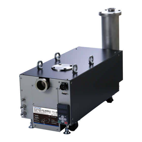
2.4 Name and Function of Parts Figure 4: Name of parts (MS120A) Table 1: Name of Parts (MS120A) Name Function Reference Cooling water outlet Connects the pipe that discharges cooling water. (Rc3/8) 3.5.2 Cooling water inlet Connects the pipe that supplies cooling water. (Rc3/8) 3.5.2... -
Page 25: Description Of Controller
2.5 Description of Controller Figure 5: Controller Table 2: Description of Controller Key/LED Function RUN indicator lamp Lights up during operation of this machine. Refer to "Table 3: Display and Status of Indicator Lamp." REV indicator lamp Refer to "Table 3: Display and Status of Indicator Lamp." ALM indicator lamp Lights up when an alarm is activated on this machine. - Page 26 Key/LED Function LEFT key Switch which moves the digit to the left in the controller operation mode. UP key / DOWN key Switch which selects the status to monitor or proceed to the next item and data. / RIGHT key (RESET Switch which moves the digit in the controller operation mode to the right.
- Page 27 Transition of data display Power ON display) (Rotation speed Description of key operation (Normal rotation) (Frequency command display) “XX”と示されているところは、本機それぞれ The display areas with "XX" show the の実際の状態を表示します。 respective actual status of this machine. (Parameter setting mode) (Monitor display) (Output power display) (Output current display) Figure 6: Transition diagram of data display YO20-0938-DI-001-00...
-
Page 28: System Configuration
2.6 System Configuration The area surrounded by the broken line below falls within the customer's responsibility. Customers are responsible for preparing and managing these pipes, wires, and pieces of equipment. 3-phase power supply Ground-fault interrupter Feed Feed Drain valve valve valve Specified amount of cooling water or less ➡... -
Page 29: Installation
(transport), while the customer is in charge of the stages from cargo reception through startup. However, the customer may fully or partly transport, unpack, or install this pump depending on the pump's terms and conditions. Packing ULVAC ・ Transport ・ULVAC entrust this task to a specified carrier Cargo reception and unpacking Customer ・ Inspection Customer ・... -
Page 30: Storage Environment Requirements
3.1.2 Storage environment requirements Store into following conditions when this machine will be stored at warehouse or clean storage room prior to installation without use for a long period of time. Ambient temperature -20 to 60°C (No freezing) Ambient humidity 95 %RH or less (No condensation) Altitude 1,000m or less of altitude above sea level... -
Page 31: Unpacking
3.2 Unpacking This machine is protected by stretch film, cushioning materials, or by other means, packed in a wooden frame or cardboard, and shipped. In case the packaging is by crate, ask a specialist to dismantle. Provide following precautions and instructions to the dismantling contractor. 3.2.1 Precautions for unpacking Never get under this machine. -
Page 32: Transfer
For transport, use cargo-handling equipment (e.g., a mobile crane) or a pallet truck. The weight of machine is as follows: MS120A: 139 kg To transport this pump, a load higher than the safety standards is required. Therefore, manually transporting it may cause lower back pain or injury. -
Page 33: How To Hoist Using Crane
3.3.1 How to hoist using crane Never get under this machine This machine may fall or topple if a forcible operation is performed or if the equipment is not sufficiently maintained. Never get under this machine. Use a crane or other cargo-handling equipment Give instructions to lift and transfer this machine using a crane or other cargo- handling equipment securely with the four eyebolts on the top of this machine when unpacking or lifting it. -
Page 34: How To Transport Using Pallet Truck
3.3.2 How to transport using pallet truck Do not transport this machine with the adjusters raised When transporting this machine via pallet truck, lower the four adjusters. If you carry this machine without the adjusters attached to the pallet, the machine may topple, causing injury or damage. -
Page 35: Installation
3.4 Installation 3.4.1 Leveling NOTES Install this machine in a horizontal position If this machine is installed on a sloping floor or if adjustment of the adjuster is unbalanced, it may cause noise or malfunction. After moving this machine to the installation location, use the adjuster to adjust the machine’s inclination and install it. - Page 36 ULVAC. Inc. Components Div. Table 5: Earthquake resistance assessments Date: May 2021 Unit MS120 Whole width of the surface of projection that falls easily Short distance from the fulcrum on the surface of projection that falls easily to the position of the center of gravity...
-
Page 37: Piping And Wiring
For MS120A, blank either the vertical or horizontal exhaust port. MS120A has two inlet ports: horizontal and vertical. Be sure to attach a flange to the unused inlet port. * MS120A assumes the use of a horizontal inlet port. When using a vertical inlet port, attach a blank flange to the horizontal inlet port. -
Page 38: Dedicated Silencer (Separately Packed)
3.5.2 Dedicated silencer (Separately packed) NOTES Install the dedicated silencer in a horizontal position. If the dedicated silencer is installed on a sloping floor or if adjustment of the adjuster is unbalanced, it may cause noise or malfunction. After assembling the pipes, perform a leak test for the entire system. In the event of leakage, the process gas leaks from the pump, which may affect the human body. -
Page 39: Cooling Water Piping
3.5.3 Cooling water piping Use appropriate joints NOTES The cooling water port of this machine is Rc 3/8. Connect appropriate joints to the cooling water piping. Do not confuse between inlet cooling water port and the outlet cooling water port. NOTES Items to comply with in the use of cooling water piping Comply with the items described below for cooling water and piping. - Page 40 Joints and pipes with a resistant water pressure of 0.9MPa or more Heatproof temperature: 70°C or more Table 7: Piping specifications Supply pressure (MPa) 0.1 ~ 0.3 Differential pressure between inlet and outlet (MPa) Cooling water Flow rate (L/min) MS120A:>4.0 Feed water temperature (°C) 10 ~ 30 (non-condensing) YO20-0938-DI-001-00...
-
Page 41: Purge Gas
3.5.4 Purge Gas This machine has a purge gas introduction mechanism. If the target gas contains condensable gas and moisture, liquid may collect in the final stage of the pump. Therefore, use purge gas to prevent the gas from liquefying and accumulating inside the pump body. In addition, for explosive/flammable/combustion-supporting gas, dilute it with purge gas to the extent that the danger is eliminated. -
Page 42: Drain
Specifications of connections ■ Pipe fittings of φ6.35 mm Applicable piping ■ Pressure resistance: fittings of 0.9 MPa or more and SUS piping with an outer diameter of φ6.35 mm Heatproof temperature: 100℃ or more Supply pressure: 0.09 to 0.11 MPaG Flow rate: 48 to 55 SLM (values as a guide) Figure 12: Purge gas supply pressure and flow rate (for reference) 3.5.5 Drain... -
Page 43: Electric Wiring
3.6 Electric Wiring 3.6.1 Electric wiring Electric wiring must be carried out by qualified personnel Electric wiring must be carried out by qualified personnel. Before installing the wiring, turn off the primary ground-fault interrupter. Before installing the wiring, turn off the primary ground-fault interrupter. Never leave the voltage applied during the work. - Page 44 ● In addition, a high-frequency leakage current occurs as an inverter is used inside. When using a ground-fault interrupter other than the specified ones with measures already taken against high frequency, use one with a sensed current of 200 mA or more. Table 8: List of power capacities and ratings of recommended ground-fault interrupters Rating List 200V...
-
Page 45: Wiring For Remote Control
3.6.2 Wiring for remote control Wiring must be installed by qualified personnel. Electric wiring must be carried out by qualified personnel. Before installing the wiring, turn off the primary ground-fault interrupter. Before installing the wiring, turn off the primary ground-fault interrupter. Never leave the voltage applied during the work. - Page 46 ■ Pin assignment of remote control wiring Pin assignment Item Specifications Pump Start CLOSE: Operation OPEN: Stop Alarm Reset CLOSE: Reset External Error CLOSE: Error OPEN: Normal Spare Unable to use Start check CLOSE: Running OPEN: Stopped Alarm CLOSE: Normal OPEN: Alarm IN COM External interlock...
- Page 47 Figure 16: I/O block diagram for remote control wiring YO20-0938-DI-001-00...
-
Page 48: Operation
4. Operation 4.1 Precautions on operation Do not use any gas other than inability gas The pumping of toxic gas, flammable gas, combustible gas, corrosive gas, explosive gas and particle gas, may damage this machine and hazardous. Furthermore, the chemical reaction of remaining gases and/or generated particle and gases may cause the explosion, not only during operation but also after stop operation. - Page 49 Use water with fewer impurities for cooling water It is recommended to use water with fewer impurities (e.g. industrial water; refer to the table below) for cooling water of this machine. In the cooling water system of this machine, water scale, such as calcium carbonate, settles on depending on the water quality, which may reduce the cooling water flow rate.
-
Page 50: Preparation For Operation
4.2 Preparation for Operation 4.2.1 Pre-Operation Check Before operating this machine, reconfirm the following. 1. Make sure that the cooling water pipe, power connector, and signal connector are connected. 2. Open the cooling water valve and check that there is no cooling water leakage. 3.... -
Page 51: How To Start/Stop
4.3 How to Start/Stop Start/Stop the pump by starting/stopping the inverter as much as possible. NOTES When performing the start/stop operation by turning ON/OFF the MC on the power supply side, the inverter used inside may fail if it is done frequently. From the viewpoint of the life of the relay contacts inside the inverter and the electrolytic capacitor, it is not recommended to start/stop by turning ON/OFF the MC on the power supply side. -
Page 52: Monitor Display
4.4 Monitor Display 4.4.1 How to operate monitor display To check the state of each pump, select "Monitor display" on the controller and follow the procedure below: 1. Turn on the power. The initial screen appears. 2. Until (Monitor display) appears on the controller, press and、... -
Page 53: Parameter List
4.5 Parameter List 4.5.1 U3: Alarm history To display the alarm history, use the U3 parameter. Table 11: List of alarm history parameters Name Function Details on the previous alarm Displays details on the previous alarm. U3-01 Details on the 2nd-to-last alarm Displays details on the 2nd-to-last alarm. -
Page 54: U4: Operation Monitor
4.5.2 U4: Operation monitor To display operating information of this machine, use the U4 parameter. Table 12: Parameter list on operation monitor Name Function Displays the cumulative operating time of this U4-01 Cumulative operating time machine. U4-08 Inverter temperature Displays the inverter temperature. YO20-0938-DI-001-00... -
Page 55: Maintenance And Inspection
If this pump is stored for a long period of time without being operated (at least six months), trouble may occur when the pump is operated due to rusting. If the pump has not been used for a long period of time, request an inspection from your local ULVAC service center before using the pump. -
Page 56: Overhaul
Especially for long-distance overland transportation under poor road surface conditions, it is recommended to transport to the installation site under the same packing condition as when it was shipped from ULVAC. If it is left in a high temperature and high humidity environment for a long time, it may cause a malfunction due to corrosion of mechanical parts or performance deterioration of electrical parts. -
Page 57: Troubleshooting
4.2.1 The power cannot be Wrong connector wiring Install wiring correctly. 3.6.1 turned on. Electric leakage inside this End of Contact to ULVAC service center. machine Document No electricity is supplied. Supply power. 4.2.1 Nothing appears on the controller display. -
Page 58: Alarm Status And Measures
3.6.1 No cooling water flow Cool this machine once and then flush it with water. 3.5.2 End of Pump overload Contact to ULVAC service center. Document End of Faulty ventilation fan Contact to ULVAC service center. Document Ambient temperature is out of Operate at an appropriate ambient temperature. - Page 59 The motor overload protection is activated. (oL1) Cause Measures Reference Unable to rotate due to foreign matters. End of ➡ Contact to ULVAC service center. Document Increased back pressure. Pump overload ➡ Clean and wash the piping on the exhaust side of the 3.5.1 pump.
- Page 60 The inverter overload protection is activated. (oL2) Cause Measures Reference Unable to rotate due to foreign matters. End of Contact to ULVAC service center. ➡ Document Increased back pressure. ➡ Clean and wash the piping on the exhaust side of the 3.5.1 pump.
- Page 61 The cooling water piping is clogged, or impurities are rate mixed in the cooling water. 3.5.2 ➡ Clean the piping. Leakage from the cooling water piping End of ➡ If it is in this machine, Contact to ULVAC service Document center. YO20-0938-DI-001-00...
- Page 62 LT-4 (LT-4) Cause Measures Reference The period that the inverter It is recommended to overhaul including Last page of replacement of the inverter. needs to be replaced has this manual ➡ Contact the ULVAC service center. expired. YO20-0938-DI-001-00...
-
Page 63: How To Restart The Pump After An Alarm
Use shielded cables for remote control wiring. Transmission noise is propagated ➡ Securely establish a ground. from the wiring for remote control. End of Controller wiring failure Contact to ULVAC service center. Document Indication Alarm Name Status External abnormality An external abnormality signal has been input in (EF3)... -
Page 64: Specifications
7. Specifications 7.1 Performance Specifications Model MS120A Maximum Displacement / hr ※ atmospheric pressure Ultimate pressure ≦0.6 Power-supply voltage (Select) 3-phase, 200 to 240±10% or 380 to 480±10%. 50/60 Hz At ultimate Approximate pressure power Under consumption maximum load Motor capacity Amount of cooling water >4.0... -
Page 65: External Dimensions
7.2 External Dimensions MS120A Figure 17: External dimensions of MS120A YO20-0938-DI-001-00... -
Page 66: Appendix
Appendix Major Replacement Parts The list of parts that must be replaced during an overhaul is as follows. The replacement timing differs depending on the part. The recommended replacement periods indicated in the table below are for reference. Actual periods may differ depending on usage conditions and the environment. Table 14: Major replacement parts Category Parts Name... - Page 67 YO20-0938-DI-001-00...
- Page 68 YO20-0938-DI-001-00...
- Page 69 YO20-0938-DI-001-00...
Need help?
Do you have a question about the MS120A and is the answer not in the manual?
Questions and answers