Table of Contents
Advertisement
Quick Links
Advertisement
Table of Contents

Related Manuals for Ulvac UTM300B


Summary of Contents for Ulvac UTM300B
- Page 1 SK00-2200-AI-144-01(263-43163A) INSTRUCTION MANUAL TURBO MOLECULAR PUMP Model UTM300B Before using this product, be sure to read this operation manual. Keep this manual with care to use at any time. ULVAC, Inc. Components Division http://www.ulvac.co.jp/...
-
Page 2: Introduction
Every effort has been made to prepare an accurate and complete manual, but if an error or omission should be discovered, revisions might not be possible immediately. ULVAC does not take responsibility for any effects that may result from the use of this manual. Copyright © 2014 ULVAC,Inc.All rights reserved. -
Page 3: Precautions For Safe Operation
WARNING Turbo molecular pump repair and/or power supply repair can be very hazardous. Only trained technicians who are authorized by ULVAC may do service of products. WARNING Neither overhaul nor modify the pump proper and the controller without admission. - Page 4 WARNING Do not operate the turbo molecular pump until safety is confirmed. ・The rotor assembly of the turbo molecular pump rotates at high speed. Large rapid shutdown torque should be generated when abnormality occurs in the pump by any chance. Incidental accident will cause the pump to drop out and to make a catastrophe if the pump is fixed by insufficient method.
- Page 5 CAUTION Avoid to install the pump at the following places. (1) Place where the pump is inevitably exposed to significant vibration and impact. (2) Unstable place. (3) Place where the pump is inevitably exposed to magnetic field and radioactive ray. The pump proper is a precision machine.
-
Page 6: Operating Precautions
CAUTION The following "CAUTIONS" are to prevent operation anomalies. ○ Operating Precautions (1) Do not interrupt the electrical power operating the turbo molecular pump while the turbo molecular pump is in operation. (2) Protect the pump from any and all types of impact during operation. Impacts can also be transmitted via the flange, so be careful of impacts near the pump as well. -
Page 7: Explanation Of Label
(4) SECURITY seal This label certificates that the product was made or maintenanced by ULVAC or by ULVAC authorized facility. In case "this label is removed" or "there is a mark showing once this label has been removed", ULVAC warranty shall not be... -
Page 8: Location Of Label
○ Location of label ラベル貼付位相... -
Page 9: Warranty Period
(1) Scope and exclusion of warranty The scope of warranty is limited to the Pump only. ULVAC will repair this pump free of charge for a period of twelve (12) months from the date of delivery in case it failed due to defects in design or manufacturing during pumping down of air or nitrogen gas. - Page 10 (1) In case, special agreement or memorandum for specifications is made individually, it comes in first. (2) Buyer shall inform ULVAC when this product is exported out of Japan. In the meantime, Buyer shall take necessary procedures according to Foreign Exchange and Foreign Trade Law.
- Page 11 This page is intentionally left blank.
-
Page 12: Table Of Contents
Table of contents Table of contents Introduction ……………………………i Copyrights and Disclaimers ……………………………ii Precautions for Safe Operation ○ Operating Precautions ……………………………………v ○ Explanation of label ………………………………………………vi ○ Location of label ………………………………………………vii ○ Warranty period ……………………………………viii ○ Conditional warranty ……………………………………viii ○ Scope of the warranty ……………………………………viii ○... -
Page 13: Table Of Contents
Table of contents ……………………………10 2.4.1 Venting Valve ……………………………10 2.4.1.1 General Description ………10 2.4.1.2 Installation of Venting valve ……………………………11 2.4.1.3 Delay Venting Mode ………………………………………12 2.4.2 Cooling Fan Section 3 CONSTRUCTION AND PRINCIPLE 3.1 Pump Construction…………………………………………………14 ……………………14 3.2 Principle of Turbo Molecular Pumping ………………………………………………16 3.3 Control system Section 4 SPECIFICATIONS... - Page 14 Table of contents Section 6 OPERATION …………………………………………………………36 6.1 Overview ……………………36 6.1.1 Introduction : Operation Modes ………………………………………38 6.2 Startup Preparation …………38 6.2.1 Start-up Preparation Sequence in LOCAL Mode …………38 6.2.2 Start-up Preparation Sequence in logic interface …38 6.2.3 Start-up Preparation Sequence in RS-485 communication …………………………………………………………39 6.3 Start-up ……………………39...
- Page 15 Table of contents Section 7 GAS PURGE Section 8 TURBO MOLECULAR PUMP RECONDITION ……………………56 8.1 Recommended maintenance intervals ……………………57 8.2 Turbo Molecular Pump Decontamination ………………………………………57 8.3 Bearing Replacement ………………………………………57 8.4 Check of the rotor blades ………………………………………58 8.5 Controller Replacement ……………………59 8.6 Turbo Molecular Pump Return Request Section 9 TROUBLESHOOTING ………………………………………62...
- Page 16 Table of contents Appendix A COMMUNICATIONS ……………………………A-2 A1 GENERAL SPECIFICATION …………………A-3 A2 PUMP TO COMPUTER CONNECTION ……………………A-3 A2.1 Communication Cable Connection ……………………A-3 A2.2 RS-485 Multi-drop Settings ………………………………………A-3 A2.3 ON-LINE request A3 SERIAL COMMUNICATIONS PROTOCOL ……………………A-4 ……………………A-4 A3.1 Basic Message Structure …………A-4 A3.2 Character to Character Time-out : 0.1 sec.
- Page 17 Table of contents This page is intentionally left blank.
-
Page 18: Section 1 Outline And Descriptions
OUTLINE AND DESCRIPTIONS ● ● ● ● ● ● ● ● ● ● ● ● ● ● ● ● ● ● ● ● ● ● ● ● ● ● ● ● ● ● ● ● ● 1.1 Outline 1.2 Descriptions 1.2.1 Outside drawing 1.2.2 Standard Accessories 1.2.3 Option Accessories... -
Page 19: Outline
SECTION 1 OUTLINE AND DESCRIPTIONS Outline The turbo molecular pump is a vacuum pump. The turbo molecular pump is used with a backing vacuum pump to create a high vacuum in a vacuum chamber. This pump is not suitable for pumping aggressive or corrosive gases. Typical Applications ;... -
Page 20: Descriptions
1.2 Descriptions Descriptions 1.2.1 Outside drawing Model Inlet flange φA P.C.D n-φd UTM300B-AC ICF152 φ152.4 19.5 φ130.3 16-φ8.5 UTM300B-AV VG100 φ185 φ160 8-φ12 UTM300B-AK ISO100-K φ130 - - Fig1-1 Outside drawing... -
Page 21: Standard Accessories
SECTION 1 OUTLINE AND DESCRIPTIONS 1.2.2 Standard Accessories Part name Notes 1 Instruction manual This manual Only VG and ICF ※ In ISO flange, protection net is built in the 1 Protection net gasket. ICF152 : Copper gasket 1 Gasket (inlet flange) VG100 : O-ring ISO100-K : Centering (with protection net) 1... -
Page 22: Section 2 Identification And Function
IDENTIFICATION AND FUNCTION ● ● ● ● ● ● ● ● ● ● ● ● ● ● ● ● ● ● ● ● ● ● ● ● ● ● ● ● ● ● ● ● ● 2.1 Pump Main Unit 2.2 Local Control Panel 2.2.1 Oparational Status 2.2.2 Operation Modes... -
Page 23: Pump Main Unit
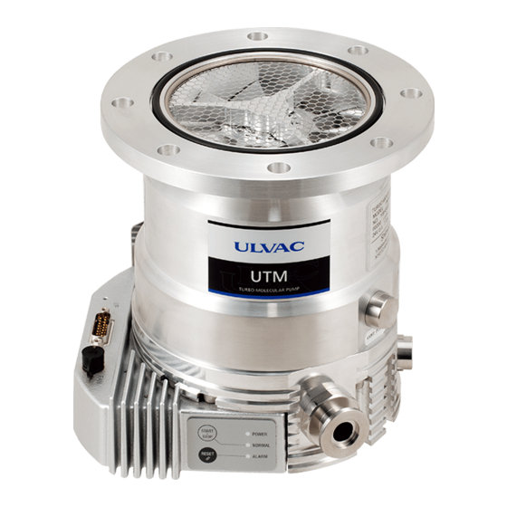
SECTION 2 IDENTIFICATION AND FUNCTION Pump Main Unit Fig. 2-1 Pump Main Unit ① INLET FLANGE ………………… Inlet flange, joint the turbo molecular pump, VG100, ICF152, ISO100-K ② OUTLET FLANGE ……………… Outlet flange, connect a backing vacuum pump or its related pipe connection, KF16. -
Page 24: Local Control Panel
2.2 Local Control Panel Local Control Panel Fig. 2-2 Switch and LED ① START/STOP button ………… Push to acceleration or deceleration during LOCAL mode. ② RESET button ………………… When occur ALARM or WARNING, after remedying the cause of the ALARM, an abnormal state is released by pushing button. -
Page 25: Oparational Status
SECTION 2 IDENTIFICATION AND FUNCTION 2.2.1 Oparational Status This instruction manual defines the operational status of a turbo molecular pump, as shown in the following table. Description Operational status [STOP] Rotor of the turbo molecular pump stops. (Motor drive OFF) [ACC] Rotor of the turbo molecular pump accelerates. -
Page 26: Interface Connector
2.3 Interface Connector Interface Connector Fig. 2-3 Interface Connector ① Cooling fan connector …………… Connector for cooling fan ② Interface connector ……………… Connector for power supply, RS-485, digital input / output, analog output. (Refer to Section 6.7 "Interface Connector") -
Page 27: Optional Accessories
SECTION 2 IDENTIFICATION AND FUNCTION Optional Accessories 2.4.1 Venting Valve 2.4.1.1 General Description To maintain the cleanliness of your vacuum system, we recommend that you vent the pump (or vacuum system) whenever you switch the turbo molecular pump off. Otherwise, oil mist on the backing vacuum side spread to the turbo molecular pump or vacuum system. -
Page 28: Delay Venting Mode
2.4 Optional Accessories 2.4.1.3 Delay Venting Mode If "Delay venting mode" is selected by RY1 operation setting, venting valve operation is as follows. 【Example of the operation of venting valve (when the delay time is 10 seconds (Note 1))】 ① STOP signal is input to the controller, and TMP decelerates. ↓... -
Page 29: Cooling Fan
SECTION 2 IDENTIFICATION AND FUNCTION 2.4.2 Cooling Fan Fig. 2-5 shows how the cooling fan (P/N : 263-44455) is fitted to the pump. CAUTION Do not shut off the ventilation, or else pump and controller get heated and it is failed. In order to secure sufficient air flow passage, the domain of less than 50 mm of front side of the cooling fan should leave space. -
Page 30: Section 3 Construction And Principle
CONSTRUCTION AND PRINCIPLE ● ● ● ● ● ● ● ● ● ● ● ● ● ● ● ● ● ● ● ● ● ● ● ● ● ● ● ● ● ● ● ● ● 3.1 Pump Construction 3.2 Principle of Turbo Molecular Pumping 3.3 Control system... -
Page 31: Pump Construction
SECTION 3 CONSTRUCTION AND PRINCIPLE Pump Construction Fig. 3-1 is a sectional drawing of a turbo molecular pump. The built-in high frequency motor (1) is accelerated to the specified revolutions (speed) by the high frequency power supply unit. Rotor blades (3) are fitted onto the drive shaft (2) and the stator blades (4) are arranged in between the rotor blades. - Page 32 3.2 Principle of Turbo Molecular Pumping Fig. 3-1 Pump Sectional Drawing (1) Motor (6) Ball bearing (11) Protective net (2) Drive shaft (7) Permanent magnet (12) Controller (3) Rotor blade (8) Touch-down bearing (4) Stator blade (9) Inlet flange (5) Spacer (10) Outlet flange...
-
Page 33: Control System
SECTION 3 CONSTRUCTION AND PRINCIPLE Control system The controller (Fig. 3-1 (12)) includes the high frequency three phase pulsed power system. This system rotates the rotor inside the pump at a rated rotational speed. Since it controls the turbo molecular pump externally, by remote control, the control system includes RS-485 serial interface ports, in addition to input/output ports for contact signals. -
Page 34: Section 4 Specifications
SPECIFICATIONS ● ● ● ● ● ● ● ● ● ● ● ● ● ● ● ● ● ● ● ● ● ● ● ● ● ● ● ● ● ● ● ● ● 4.1 Specification 4.1.1 Pump Main Unit 4.1.2 Power Supply Unit 4.4 Maximum allowable flow rate 4.5 Environmental Conditions... -
Page 35: Specification
60000 rpm Start-up time (> 80 %) 3.5 mimutes (Note 7) Allowable gas (Note 8) ,He, H Mounting position In any desired direction Noise (by ULVAC's method) 50 dB(A) or less (Note 9) Admissible ambient Radial direction 3 mT magnetic field... -
Page 36: Power Supply Unit
(Note 7) Input voltage : 24.0 VDC, backing pressure : less than 5 Pa. (Note 8) Do not use reactive gasses, corrosive gasses or gas including gallium. Consult with ULVAC about other kind of gasses. (Note 9) It is the measure of the ISO flange. -
Page 37: Maximum Inlet Pressure
SECTION 4 SPECIFICATIONS Maximum inlet pressure Condition Maximum continuous inlet pressure Cooling method Ambient temperature Backing pump Gas type (Note 1) (Note 2) 5 to 25 degrees C. 0.06 Pa Natural 30 degrees C. 0.045 Pa convection 35 degrees C. 0.026 Pa 120 L/min 5 ~ 25 degrees C. -
Page 38: Maximum Allowable Flow Rate
Yes (Note 3) 40 mL/min (Note 1) Consult your ULVAC representative before using gasses except shown in above table. (Note 2) mL/min : volume flow rate at 0 degrees C., 1atm. (Compatible with SCCM.) (Note 3) Recommended gas purge condition : N... -
Page 39: Environmental Conditions
SECTION 4 SPECIFICATIONS Environmental Conditions Use : Indoor, Altitude max : 2000 m, Installation conditions Overvoltage category I, Pollution degree 2 (Refer to UL/EN 61010-1 standard) IP classification 40 5 to 35 degrees C. (natural convection) Temperature Operation 5 to 40 degrees C. (forced air) (above dew point) Storage -25 to 65 degrees C. -
Page 40: Section 5 Installation
INSTALLATION ● ● ● ● ● ● ● ● ● ● ● ● ● ● ● ● ● ● ● ● ● ● ● ● ● ● ● ● ● ● ● ● ● 5.1 Installation 5.1.1 Pump Mounting Direction 5.1.2 Installation of the Pump 5.1.2.1 Instruction and Lifting Method 5.1.2.2 Installation... -
Page 41: Installation
SECTION 5 INSTALLATION Installation 5.1.1 Pump Mounting Direction This turbo molecular pump can be installed in vertical, horizontal, inverted, or oblique position. (Refer to Fig. 5-1) Fig. 5-1 Mounting Direction of the Turbo Molecular Pump... -
Page 42: Installation Of The Pump
5.1 Installation 5.1.2 Installation of the Pump WARNING To ensure safety, do not operate the pump. ・The rotor assembly of the turbo molecular pump rotates at high speed. Large rapid shutdown torque should be generated when abnormality occurs in the pump by any chance. Incidental accident will cause the pump to drop out and to make a catastrophe if the pump is fixed by insufficient method. -
Page 43: Instruction And Lifting Method
SECTION 5 INSTALLATION 5.1.2.1 Instruction and Lifting Method This puroduct lift the pump in the manner shown in Fig. 5-2. Fig. 5-2 Lifting Method... -
Page 44: Installation
UTM300B 5400 N・m (Note) Rapid shutdown torque is the typical value measured by the ULVAC’s test condition. The torque to transmit to host equipment might be different according to the rigidity of host equipment. Host equipment should be designed to have enough margins in strength. - Page 45 SECTION 5 INSTALLATION Fig. 5-4 How to use of the bolt Table 5-1 The recommended fixing bolt ■ By the inlet flange Bolt-Nut (Half screw・All screw)・Tap Fixing method By the inlet flange Inlet flange VG100 ICF152 ISO100-K (Note 1) Bolt size, Quantity M10,8 PC M8,16 PC Clamp, 4 PC...
-
Page 46: Example Of Piping Connection
5.1 Installation 5.1.3 Example of piping connection 5.1.3.1 Connection of exhaust line Connect a backing vacuum pump or its related pipe connection flange to the outlet flange of the pump. (Refer to Fig. 5-5) * marks are not attached to this turbo molecular pump set. Fig. -
Page 47: Connection Of Electrical Supply
SECTION 5 INSTALLATION Connection of electrical supply CAUTION This product requires a separate power supply (not included). The power supply should be adequately protected against a hazardous live condition. The power input voltage of this product is 24 VDC ± 5 %. Do not exceed the maximum supply voltage. - Page 48 5.2 Connection of electrical supply (Note 1) Connect all 4 pins for 24 VDC line and GND line. (Note 2) The functions can be change via RS-485 communication. (Note 3) Venting valve need to be normally closed. If you use a normally open valve, you have to change the function via RS-485 communication.
-
Page 49: Connection I/F Connector With Interface Cable (Option)
SECTION 5 INSTALLATION Fig. 5-6 Connection of I/F connector 5.2.2 Connection I/F connector with Interface Cable (Option) The connection of Interface cable (P/N : 263-44408) is shown in Fig. 5-7. Fig. 5-7 Interface Cable (P/N : 263-44408) diagram... -
Page 50: Interlock For Vacuum System
(an air suspension truck, for example). Especially when passing by rough road, we recommend that the product is transported keeping the packing condition when it ships from ULVAC. When the product is put on the high temperature / humidity environment for a long time, it causes the breakdown of the product due to corrosion of mechanical parts or performance loss of electrical parts. - Page 51 SECTION 5 INSTALLATION This page is intentionally left blank.
-
Page 52: Section 6 Operation
OPERATION ● ● ● ● ● ● ● ● ● ● ● ● ● ● ● ● ● ● ● ● ● ● ● ● ● ● ● ● ● ● ● ● ● 6.1 Overview 6.1.1 Introduction : Operation Modes 6.2 Startup Preparation 6.2.1 Start-up Preparation Sequence in LOCAL Mode 6.2.2 Start-up Preparation Sequence in logic interface... -
Page 53: Overview
SECTION 6 OPERATION Overview CAUTION Do not turn off the power during pump operation. 6.1.1 Introduction : Operation Modes When the power is input, the pump starts self-diagnosis. When the result is normal, operation is enabled. When an abnormal condition is detected, the ALARM lamp lights up in orange. - Page 54 6.1 Overview Table 6-1 LOCAL and REMOTE Modes mode lamp state Start/Stop procedure LOCAL POWER lamp flashes. The pump can be started or stopped by holding down the START/STOP button. REMOTE POWER lamp lights up. The pump can be started or stopped via a contact input, RS-485 or RS-485 communication.
-
Page 55: Startup Preparation
SECTION 6 OPERATION Startup Preparation 6.2.1 Start-up Preparation Sequence in LOCAL Mode (1) Please input the power and check if the POWER lamp (Fig. 2-2 (3)) lights. Maintained push the RESET button (Fig. 2-2 (2)) to change from REMOTE mode to LOCAL mode. -
Page 56: Start-Up
6.3 Start-up Start-up 6.3.1 Start-up Sequence in LOCAL Mode (1) Start-up begins when the 6.2.1 "Start-up Preparation Sequence in LOCAL Mode" is complete. (2) Maintained push the START/STOP button (Fig. 2-2 (1)). (3) Pump acceleration starts. The NORMAL lamp (Fig. 2-2 (4)) blinks quickly. (4) When the rotational speed reaches 80 % rated value, the NORMAL lamp lights. -
Page 57: Shutting Down
SECTION 6 OPERATION Shutting Down CAUTION When reducing internal pressure of the turbo molecular pump up to around the atmospheric pressure by use of inert gas, etc., adjust the pressure reducing valve so that the internal pressure of the same pump does not exceed 20 kPa GAUGE. For shut-down of the turbo molecular pump, follow the sequence below. -
Page 58: Shutting Down Sequence In Rs-485 Communication
6.4 Shutting Down 6.4.4 Shutting Down Sequence in RS-485 communication (1) Input the "STOP" command via RS-485 communication. The pump deceleration starts. Status is changed from "NORMAL" or "ACCELERATION" to "IDLE". (2) Wait until status changes to "STOP" status. (3) Shut the power off. Further, in such a case when a hydraulic rotary vacuum pump is used as backing vacuum pump and there is possible reverse flow and diffusion of oil from the backing vacuum pump, return the pump internal pressure to atmospheric pressure using dry nitrogen gas, after complete... -
Page 59: Variable Speed Operation
SECTION 6 OPERATION Variable Speed Operation CAUTION When using the variable speed function to change the pump rotation rate, use a rotation rate that does not cause resonance with other devices installed at the site. NOTICE The variable rotation speed function is only available by remote control or RS-485 operation. Rotation speed cannot be varied by local control. -
Page 60: Operation From Start-Up To Low Speed Rotation
6.5 Variable Speed Operation 6.5.2 Operation from Start-up to Low Speed Rotation This is the procedure until low-speed rotation is achieved when the speed setting is made with the pump stopped. 6.5.2.1 Logic interface Operation (1) Start-up begins when the 6.2.2 "Start-up Preparation Sequence in logic interface" is complete. -
Page 61: Operation From Rated Speed Rotation To Low Speed Rotation
SECTION 6 OPERATION 6.5.3 Operation From Rated Speed Rotation to Low Speed Rotation The following procedure is used to change the rotation speed setting and operate in the low- speed mode when currently operating at the rated speed or accelerating at a speed greater than low speed rotation. -
Page 62: Operation From Low Speed Rotation To Rated Speed Rotation
6.5 Variable Speed Operation 6.5.4 Operation from Low Speed Rotation to Rated Speed Rotation This is the procedure to select normal speed operation during low speed rotation. 6.5.4.1 REMOTE Operation (1) Cancel the "LOW SPEED" signal (Refer to Table 6-6) inputted in the remote-control connector. -
Page 63: Software Operation
SECTION 6 OPERATION Software Operation NOTICE Setting data can be loaded and overwritten only via RS-485 communication. Software functions are indicated in the table below (Refer to Table 6-2). Table 6-2 Software Operating Functions Function Descripition Status Operation mode LOCAL, REMOTE or RS-485. Rotational Speed Motor current Run Status... -
Page 64: Interface Connector
6.7 Interface Connector Interface Connector 6.7.1 Specification The controller is provided with remote control connector for connection with remote operation, alarm signals, etc. Please wire connection with reference to Table 6-3, Table 6-4, and Table 6-5. You must use a shielded wire and the shield wire should be connected the connector case. Table 6-3 Interface connector circuit Input/ Input... - Page 65 SECTION 6 OPERATION Table 6-4 Acceleration / Deceleration by Interface connector Connection By momentary type By alternate type switch method START/STOP switch Wiring connection Pump start by short-circuiting Pump start, with the contact close or photo (2) to (7), (15). transistor ON ((2) to (7), (15) short-circuit).
-
Page 66: Pin Assignment
6.7 Interface Connector 6.7.2 Pin Assignment Table 6-6 Pin assignment of interface connector Input/ Pin No. Name Designation factory settings Output Input + 24 VDC in Voltage supply for the TMP controller (Note 1) To connect this pin to GND : Start pump Input START / STOP To open this pin : Stop pump... -
Page 67: Setting For Interface Connector Operation
SECTION 6 OPERATION 6.7.4 Setting for Interface Connector Operation Items of the following table can change setting via RS-485 communication. Name Table of settings default settings RY1 (relay output 1) "0000" : RY1 is ON when DI1 is ON “0004” operation setting "0001"... -
Page 68: Communication Specifications
6.8 RS-485 Communication Specifications RS-485 Communication Specifications 6.8.1 Transfer Specifications Interface RS-485 Synchronous system Asynchronous Transmission rate 9600 bps (fixed) Character configuration Start bit : 1 Data bits : 8 Parity : None Stop bit : 1 Flow control None Number of units connected Max 32 Connector and Pin assignment... - Page 69 SECTION 6 OPERATION (2) Cables used RS-485 is a differential transmission and use twisted-pair cables in combinations as shown in Fig. 6-3. (3) Connecting the terminator resistor (Terminator) This product has a terminate resistor (120Ω ) inside the controller, and the setting of terminator can be switched ON and OFF.
-
Page 70: Section 7 Gas Purge
GAS PURGE ● ● ● ● ● ● ● ● ● ● ● ● ● ● ● ● ● ● ● ● ● ● ● ● ● ● ● ● ● ● ● ● ●... - Page 71 SECTION 7 GAS PURGE This product includes a port for purging gasses in optional specification. It is possible that the pump temperature is increased by the gas load affects the bearing exhange period. When operating in more than 50 % of the allowable flow rate, please use a purge gas in order to suppress the temperature increases.
-
Page 72: Section 8 Turbo Molecular Pump Recondition
TURBO MOLECULAR PUMP RECONDITION ● ● ● ● ● ● ● ● ● ● ● ● ● ● ● ● ● ● ● ● ● ● ● ● ● ● ● ● ● ● ● ● ● 8.1 Recommended maintenance intervals 8.2 Turbo Molecular Pump Decontamination 8.3 Bearing Replacement 8.4 Check of the rotor blades... -
Page 73: Recommended Maintenance Intervals
SECTION 8 TURBO MOLECULAR PUMP RECONDITION Recommended maintenance intervals It is different for deterioration progress speed of each part changes greatly by pump condition. Refer to the following list as overhaul. These are not terms of warranty. Refer to Section 8.5 "Controller Replacement" for Power supply unit. Process Recommended maintenance intervals... -
Page 74: Turbo Molecular Pump Decontamination
The ball bearing (Fig. 3-1 (6)) and the touch-down bearing are the component of this pump that is subjected to friction and wear. The replacement of (the ball bearing and) the touch-down bearing is done only by ULVAC or an approved service company. -
Page 75: Controller Replacement
Replacement of parts inside controller can not be carried out but will exchange the whole controller. The replacement of the controller unit is done only by ULVAC or an approved service company. Table 8-2 Estimated Service Life for Parts... -
Page 76: Turbo Molecular Pump Return Request
ULVAC will accept and perform service only on turbo molecular pumps that have been properly prepared as stated in (1) and (2) above. ULVAC will advice the customer of any failure precaution/prevention procedures that are appropriate to each individual turbo molecular pump service request. - Page 77 SECTION 8 TURBO MOLECULAR PUMP RECONDITION This page is intentionally left blank.
-
Page 78: Section 9 Troubleshooting
TROUBLESHOOTING ● ● ● ● ● ● ● ● ● ● ● ● ● ● ● ● ● ● ● ● ● ● ● ● ● ● ● ● ● ● ● ● ● 9.1 Vacuum Pressure Rise 9.2 Abnormal Noise and/or Vibration 9.3 Nothing Happens After an Operation is Made 9.4 Power Failures 9.5 Alarm Detection Capabilities... -
Page 79: Vacuum Pressure Rise
SECTION 9 TROUBLESHOOTING Vacuum Pressure Rise A rapid rise of vacuum pressure in the turbo molecular pump causes the internal motor of the turbo molecular pump to start coasting and the ALARM lamp (Fig. 2-2 (5)) lights. Do not suddenly increase the pressure or let atmospheric air enter the pump during pump operation. -
Page 80: Nothing Happens After An Operation Is Made
9.3 Nothing Happens After an Operation is Made Nothing Happens After an Operation is Made Table 9-1 Nothing Happens After an Operation is Made PROBLEM POSSIBLE CAUSES CORRECTIVE ACTION Section Input the power, but the The GND pin (7, 15) Ensure that the GND pin (7, 15) turbo molecular pump and the 24 VDC pin (1, 5) are... -
Page 81: Power Failures
(Note 1) UTM300B about 18 minutes (Note 1) The time is typical for regenerative braking from the rated speed. Actual time will very depending on vacuum conditions inside the pump and the rotational speed when the power fails. -
Page 82: Alarm Detection Capabilities
9.5 Alarm Detection Capabilities Alarm Detection Capabilities The fault detection functions shown in Table 9-6 "Table of Alarms" and Table 9-7 "Table of Warnings" are incorporated for protection in the event of a problem with the turbo molecular pump or controller. When an error is detected, check the ALARM lamp (Fig. - Page 83 SECTION 9 TROUBLESHOOTING Table 9-4 If the ALARM Lamp Lights Alarm Sec- Alarm Name Possible Cause Remedy Code tion POWER FAILURE Power failure Wait for the power to be restored. Reduction in the Check the 24 VDC power supply. power suppluy voltage TMP:OVERLOAD Drop in rotation...
- Page 84 9.5 Alarm Detection Capabilities Table 9-5 If the ALARM Lamp Flashes Alarm Sec- Alarm Name Possible Cause Remedy Code tion TMP:BRG TEMP WARN Increased pump Check that the ambient temperature bearing temperature. around the pump is within the specified range. Check that no load in excess of the specified range is continuously applied to the pump.
- Page 85 SECTION 9 TROUBLESHOOTING Table 9-6 Table of Alarms Alarm Alarm Name Possible Cause Protective Action Code POWER FAILURE Power failure or reduction in the power supply Free run voltage. (motor stop) TMP:OVERLOAD After accelerating to 80 % of the designated speed or low-speed setting, the speed dropped below 80 % due to overloading etc TMP:TEMP/MB CABLE...
- Page 86 Appendix A COMMUNICATIONS ● ● ● ● ● ● ● ● ● ● ● ● ● ● ● ● ● ● ● ● ● ● ● ● ● ● ● ● ● ● ● A1 GENERAL SPECIFICATION ● A2 PUMP TO COMPUTER CONNECTION ●...
- Page 87 Appendix A COMMUNICATIONS GENERAL SPECIFICATION The UTM300B controller contaion serial interfaces conforming to and RS-485 specifications. The following functions are available by connecting a computer with communication capacity to these interfaces and creating the appropriate software. The RS-485 interface permits multi-drop connections, allowing multiple power supplies to be connected to a single computer.
- Page 88 A2 PUMP TO COMPUTER CONNECTION PUMP TO COMPUTER CONNECTION A2.1 Communication Cable Connection Turn off the power switch and the computer to be connected. Connect the RS-485 signal to the communications port of the computer with a cable, referring to Instruction manual of the pump. A2.2 RS-485 Multi-drop Settings The RS-485 interface multi-drop function is used to connect multiple turbo moleculer pump to a single computer.Turn off the multi-drop function if the RS-485 is used instead of RS-232C to...
- Page 89 Appendix A COMMUNICATIONS SERIAL COMMUNICATIONS PROTOCOL Communications software, between the power supply and customer equipment should be design according to the following specifications. A3.1 Basic Message Structure A basic transmit and receive message begins with the characters "MJ" and ends with a carriage return code (0dH : xxH means hexadecimal code).
- Page 90 A3 SERIAL COMMUNICATIONS PROTOCOL A3.3 Command to Answer Time-out: 1 sec. Delays between COMMAND and ANSWER messages, longer that 1 sec., shall be considered as a transmission line failure and special considerations should be made to re-send the message. The turbo molecular pump re-sends a COMMAND, if it does not receive and ANSWER within a one second period.
- Page 91 Appendix A COMMUNICATIONS TABLE OF COMMANDS Table A-2 Table of Commands Command Command / Type Name character Sub-command character string answer string Operation mode Command Operation mode check None On-line request None Off-line request None Answer Local None Remote None RS-485 None Operation...
- Page 92 A4 TABLE OF COMMANDS Command Command / Type Name character Sub-command character string answer string History 1 Command Read alarm history ※9 xxx...xxx Send alarm history ※10 Answer No history data ※9 History 2 Read alarm history Command ※9 Send alarm history xxx…xxx ※19 Answer...
- Page 93 Appendix A COMMUNICATIONS aa : Settings number (decimal). Refer to Table A-7 "Table of Settings". bbbb : Set value (decimal). Refer to Table A-7 "Table of Settings". xxx...xxx : Any 20-character displayable character string. aa : Settings number (decimal). Refer to Table A-8 "List of RS-485 Settings". aa : Settings number (decimal).
- Page 94 A4 TABLE OF COMMANDS xxx...xxx : Refer to Table A-3 "Alarm History 2 Data Format". Table A-3 Alarm History 2 Data Format Item Number Data Comments of bytes History number 01 ~ 99 History number designated by the command. Time when the failure occurred (stored as Greenwich Mean Time) Time YYMMDDHHMM...
- Page 95 Range Description and format Model identification The pump model connected. 0000 ~ 9999 number Example : UTM300B → "0300" Rotational speed / 10 Rotational speed 0000 ~ 5000 Example : 15000 rpm → "1500" Motor drive current x 10 Motor curret 0000 ~ 0100 Example : 2.3 A →...
- Page 96 Motor current in the event of a fault. Motor current 0000 ~ 0150 Format is the same as No.04 in Table A-4. Reserved 000000 ~999999 This byte is not used for UTM300B. Reserved 0000 ~ 0100 This byte is not used for UTM300B. Reserved 0000 ~ 0100 This byte is not used for UTM300B.
- Page 97 Appendix A COMMUNICATIONS Table A-7 Table of Settings Name Range Description and format Variable speed operation setting. When set to "LOW SPEED" mode, rated rotational speed is Rotational speed 0000 / 0001 changed to preset rotational speed value which set No.04 or No.08 in this table.
- Page 98 A4 TABLE OF COMMANDS Name Range Description and format Normal speed setting [%] Normal speed setting 0500 ~ 0970 "0800" : 80.0 % The time to open venting valve since STOP signal is input to Venting valve controller. 0000 ~ 0030 operation time setting "0030"...
- Page 99 Appendix A COMMUNICATIONS COMMAND DESCRIPTION A5.1 Operation Mode Operation mode check Enables operation mode verification (LOCAL / REMOTE / RS-232C / RS-485) Action : returns an ANSWER showing present operation mode. ON-LINE request If the current operation mode is REMOTE, the operation mode is shifted to RS-232C Commands or RS-485.
- Page 100 Acceleration Start This answer is returned after the acceleration is started on a START operation. Deceleration Start This answer is not used for UTM300B. Coasting Start This answer is returned after the coasting is started on a STOP operation. Failure elimination This answer is returned if the failure cause is removed and send RESET operation command.
- Page 101 Appendix A COMMUNICATIONS A5.3 Run Status Run Status Check Commands This command requests the current status of the turbo molecular pump. Stop For a normal status, "00" is returned as the sub-command. If a warning has occurred, the 2-character alarm code is returned as the sub-command. Acceleration For a normal status, "00"...
- Page 102 A5 COMMAND DESCRIPTION A5.4 Parameters Read paramater Reads the parameter value for a designated parameter number. Commands Sends the 2-character parameter number as the sub-command. Refer to Table A-4 "Table of Parameters" for parameter number. Send parameter Returns the parameter value for the designated parameter number. The 2-character parameter number + 4-character parameter value is returned as the sub-command.
- Page 103 Appendix A COMMUNICATIONS A5.6 History Read alarm history 1 Commands Reads the alarm history for a designated alarm history number. Sends the 2-character alarm history number as the sub-command. Send alarm history 1 Returns the alarm history for the designated alarm history number. The 64-character alarm history data is returned as the sub-command in the format shown in Table A-6 "Alarm History 1 Data Format".
- Page 104 A5 COMMAND DESCRIPTION A5.7 Settings Read settings Reads the set value for a designated settings number. Sends the 2-character settings number as the sub-command. Refer to Table A-7 "Table of Settings" for setting number. Commands Write settings Overwrites the set value for a designated settings number.Sends the 2-character settings number + 4-character set value data as the sub-command.
- Page 105 Appendix A COMMUNICATIONS A5.9 RS-485 Settings Reads RS-485 setting Reads the setting value for the specified setting number. As subcommand, sends 2-character setting number. For setting numbers, refer to Table A-8 "List of RS-485 Settings". Commands Writes RS-485 setting Writes the setting value for the specified setting number. As subcommand, sends 2-character setting number and 4-character setting value.
- Page 106 A6 RS-485 COMMANDS / ANSWERS (SEND AND RECEIVE Examples) RS-485 COMMANDS / ANSWERS (SEND AND RECEIVE Examples) Table A-9 RS-485 COMMANDS / ANSWERS (SEND AND RECEIVE Examples) Direction Character String Type of Data Sent/Receive Description Remarks (Note 1) (Note 2) MJ01LS97\ Operation Mode...
- Page 107 Appendix A COMMUNICATIONS Direction Character String Description Remarks Type of Data Sent/Receive (Note 1) (Note 2) → MJ01CS8E\ Run Status Check MJ01NS00F9\ Stop MJ01NA00E7\ Acceleration MJ01NB00E8\ Deceleration MJ01NN00F4\ Normal Rotation ← Run Status MJ01FS1C05\ Failure Stop MJ01FF32E9\ Failure Idle MJ01FR15F6\ Failure Regeneration Power failure occured MJ01FB60E6\...
- Page 108 A6 RS-485 COMMANDS / ANSWERS (SEND AND RECEIVE Examples) Direction Character String Description Remarks Type of Data Sent/Receive (Note 1) (Note 2) → MJ01SR0300\ Read Settings Settings number 03 MJ01SA030000AF\ Send Settings Value Settings number 03 = 0 ← Rotational speed = NORMAL Setting →...
- Page 109 Appendix A COMMUNICATIONS RELATION OF LOCAL MODE TO REMOTE MODE OPERATIONS (1) Input of Local Control panel switch is only effective when POWER lamp is in "LOCAL" mode. (POWER lamp is FLASH.) (2) When the POWER lamp is in "REMOTE" mode (POWER lamp is ON), "REMOTE" input signal only is effective under initial status.
- Page 110 A8 TROUBLESHOOTING TROUBLESHOOTING A8.1 No Message can Transmit and Receive (1) Check the connection of RS-485 cable in reference to instruction manual of the pump. Check the polarity of RS-485 interface, because there is the case that polarity is reverse. (2) Check the transmission specification of RS-485 at computer side.
- Page 111 Appendix A COMMUNICATIONS This page is intentionally left blank. A-26...
- Page 112 Index ………………………………7 ALARM lamp …………………6 backing vacuum pump …………………………14,15 ball bearing ………………………………7 Control Panel …………………9 cooling fan connector I/F panel ……………………………………………6 ……………………………6,15 inlet flange interface connector ………………………………9 ………………………………7 NORMAL lamp ……………………………6,15 outlet flange permanent magnet …………………………14,15 ………………………………7 POWER lamp ………………………………7 RESET button …………………………………………15 rotor...
- Page 113 This page is intentionally left blank.
Need help?
Do you have a question about the UTM300B and is the answer not in the manual?
Questions and answers