Table of Contents
Advertisement
Quick Links
Advertisement
Table of Contents

Subscribe to Our Youtube Channel
Related Manuals for Ulvac VD151


Summary of Contents for Ulvac VD151
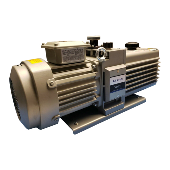
- Page 1 YK08-0028-DI-002-08 INSTRUCTION MANUAL OIL SEALED ROTARY VACUUM PUMP VD151 VD201 Before using this product, be sure to read this operation manual. Keep this manual with care to use at any time. ULVAC, Inc. Components Division http://www.ulvac.co.jp...
- Page 2 The performance and safety of the product might not be ensured if any of the devices put together did not conform to same regulations or the product itself was modified. ULVAC shall be not liable to guarantee performance and safety in such cases above. Any modification of the product by the user is out of the scope of guarantee by us and not be guaranteed in any manner.
-
Page 3: Safety Symbol Marks
YK08-0028-DI-002-08 Any part of this Instruction Manual shall be in no manner reproduced for the third party without our approval. CAUTION 0.1 Safety Symbol Marks We display symbol marks regarding the safety in this manual and on the product to make clear items to observe. -
Page 4: Safety Precautions
YK08-0028-DI-002-08 0.3 Safety Precautions Descriptions are given as the method to keep away from danger and actions that must be restricted on the use of the product. Use of this product and this Instruction Manual. Please read this Instruction Manual before starting installation, operation check or maintenance of this product to use it in long term. - Page 5 YK08-0028-DI-002-08 You are kindly requested to acknowledge that specifications and/or price of the product and description of the Instruction Manual are subject to change without prior notice for improvement. Any change shall update the version number at the top right of the WARNING Instruction Manual cover and issue the revised version.
- Page 6 Transfer Pump Weight VD151:29kg VD201:34.5kg When you carry a pump, you have a risk of giving damage to your back. Be sure to use the loading machinery (such as mobile crane) to lift up...
- Page 7 YK08-0028-DI-002-08 Countermeasure to the earthquake There is a risk that the Pump lays down or slides and breaks peripheral units if it was not correctly fixed. Be sure to give allowances to the vacuum piping and electric cables so that they absorber vibrations to prevent them from breaking and/or dismantling.
- Page 8 YK08-0028-DI-002-08 Operation Do not run the Pump on blocking the exhaust outlet or putting any device that might hamper gas passage onto the outlet. There is a risk that the pressure inside the Vacuum pump rises up to cause break or oil leak of the casing or Oil level gauge resulting in overload of the motor.
- Page 9 YK08-0028-DI-002-08 1) Do not attempt to put your hand or article in the opening of the motor; you have a risk of getting electrical shock, injury or casing a fire. 2) Do not touch any rotary section such as the motor, main spindle or spindle joint during operation of the Vacuum pump;...
-
Page 10: Types And Descriptions Of Warning Labels Displayed On This Machine And Displayed Positions
YK08-0028-DI-002-08 0.4 Types and Descriptions of Warning Labels Displayed on This Machine and Displayed Positions Warning labels are attached on the warning locations in this system. Be sure to check them before starting operation of the Pump. Before use, read through the instruction manual and fully understand its contents. - Page 11 YK08-0028-DI-002-08 INLET OUTLET...
- Page 12 YK08-0028-DI-002-08 VD151 VD201 Fig. 1 Warning Label...
-
Page 13: Acceptance And Storage Of The Pump
YK08-0028-DI-002-08 0.5 Acceptance and Storage of The Pump 0.5.1 Unpacking/Acceptance of The Pump 1) When taking out the product from the box and lifting up the pump, guide to use the cargo-handling equipment such as a crane utilizing the eyebolt located at the upper part of the pump and to transfer lifting it up. -
Page 14: Transfer
YK08-0028-DI-002-08 0.5.2 Transfer Pump Weight VD151:29kg VD201:34.5kg When you carry a pump, you have a risk of giving damage to your back. Be sure to use the loading machinery (such as mobile crane) to lift up WARNING the Pump or load it on the pallet and fix it and run the Pallet truck for its transfer. -
Page 15: Protective Device
YK08-0028-DI-002-08 Do not give the Pump a shock or lay it down. It might impair the Pump operation. CAUTION The rubber leg is attached to the base.In installing, set the pump in horizontal position, and place it so that there is no rattle. 0.6 Protective Device The pump is equipped with a three-phase 200V~240V (50/60 Hz) / 380V~460V (50/60 Hz) motor. -
Page 16: Table Of Contents
YK08-0028-DI-002-08 Table of Contents 0. Before Using This Product ........................i 0.1 Safety Symbol Marks ........................ii 0.2 Meanings of Safety Symbol Marks ....................ii 0.3 Safety Precautions ........................iii 0.4 Types and Descriptions of Warning Labels Displayed on This Machine and Displayed Positions ................................. - Page 17 8.2 Duration of guarantee ......................... 43 8.3 Warrantee scope ......................... 43 8.4 Response procedure ........................43 8.5 Disclaimer ........................... 44 8.6 Others ............................44 9. Main Displacement Parts ........................45 Request Form for Repair/Inspection of ULVAC Components /Certificate of Contamination SERVICE CENTER Contents-2...
- Page 18 Fig. 6 Terminal box internal wiring diagram ..................... 14 Fig. 7 Electrical wiring diagram ........................ 14 Fig. 8 To use Oil mist trap “Model TMX-1” for “VD151 or VD201” ............25 Fig. 9 When having mounted oil mist trap and adapter ................25 Fig.
-
Page 19: For Your Safety Use
YK08-0028-DI-002-08 1. For Your Safety Use 1.1 This Product Intrinsic Hazardous Nature and Safety Measures Before operating or checking this machine, thoroughly read this paragraph, and after fully understanding about latent danger and on how to avoid danger, perform the work. 1.1.1 Danger Leakage of dangerous gas and dangerous materials... -
Page 20: Warning Electric Shock
YK08-0028-DI-002-08 1.1.3 Warning Electric shock Factors Avoidance methods and measures 1) Be sure to cut the electricity to do electrical connection. Never fail to take the grounding. 2) Ensure to close the cover of motor terminal box and never open it during operation. Getting electrical shock... -
Page 21: Chemical Material Safety Data Sheet(Msds
YK08-0028-DI-002-08 1.2 Chemical Material Safety Data Sheet(MSDS) Chemical material used for this Pump; 1) ULVOIL R-72 (Standard) 2) ULVOIL R-42 (Cold area or winter time) The Chemical Material Safety Data Sheet introduces the chemical material potential to use or touch on operating this machine. Please IMPORTANT contact our Sales division if you are in need. -
Page 22: Pump Outline
2. Pump Outline 2.1 Characteristics The VD151 and VD201 are a compact, low noise, Gaede type two-stage vacuum pump that permits high speed rotation. Since the pump is small, light, and quite simply constructed, it is easily maintained and repaired. -
Page 23: Performance Specifications
YK08-0028-DI-002-08 2.2 Performance Specifications Table. 1 Performance specifications 型 番 VD151 VD201 Model RATED FREQENCY 設計排気速度 Displacement 14.4(240) 17.3(288) 20.2(336) 24.2(403) m3/hour (L/min) ※1 ※2 到達圧力 GV 閉 0.67 Ultimate Pressure GV Close ※2 GV 開 GV Open ※3 使用モーター 全閉外扇フランジ型3相交流モーター Motor Totally-Enclosed Fan-Cooled Flange Induction Motor kW (極数)... - Page 24 YK08-0028-DI-002-08 Fig. 2 VD151 Dimensional drawing...
- Page 25 YK08-0028-DI-002-08 Fig. 3 VD201 Dimensional drawing...
-
Page 26: Mounting
YK08-0028-DI-002-08 3. Mounting You are requested to install and operate the product in compliance with the laws and regulations relating to the safety, e.g. Fire Defense Law, Electric wiring regulation and so on in the country and region you use the product. - Page 27 Should the oil touched to your hand are entered in your eye, immediately follow the emergency treatment described on the MSDS. Ensure to use the vacuum pump oil designated by ULVAC. Operation using oil other than designated shall be out of our scope of guarantee as it might impair the pump performance and shorten the life cycle.
-
Page 28: Air Suction Piping
YK08-0028-DI-002-08 3.3 Air Suction Piping 1) Before connecting the piping to the pump, clean the vacuum chamber, piping, vacuum valve, etc. well. If they are contaminated, the ultimate pressure may be higher or a longer time may be required to reduce pressure to the specified level. Wear a pair of gloves to touch any vacuum section. -
Page 29: Exhaust Connection
YK08-0028-DI-002-08 3.4 Exhaust Connection Use the “G1” (JIS B0202-Parallel pipe threads-) for connection between the Outlet of the pump and the duct piping. It is recommended to provide an oil mist trap to reduce oil consumption and to trap oil mist. If the pipe connected to the Exhaust outlet had a small diameter or attached foreign substance inside, there is a risk that the pressure inside the Vacuum pump rises up to cause break or oil leak of the casing... -
Page 30: Electrical Connection
YK08-0028-DI-002-08 3.5 Electrical Connection Conduct the electrical connection referring to the “Fig. 6 and Fig. 7”. IMPORTANT Use crimping terminals for the connection and tighten screws. Check also screws fixing the connector tighten. Motor rotation direction is counterclockwise viewed from the motor side. Be sure also to put a safety circuit such as Electromagnetic breaker for the electrical connection. - Page 31 YK08-0028-DI-002-08 Table. 2 Electric capacity of the motor overload protector AC200V~AC460V 3Phase 適合電線 定格電流 配線用遮断機 サーマルリレー ポンプ型番 モータ容量 power cords RATED CURRENT Breaker Thermal relay MODEL 2.90 (200V/50Hz) 2.90 (200V/50Hz) 3.10 (220V/50Hz) 3.10 (220V/50Hz) 3.30 (230V/50Hz) 3.30 (230V/50Hz) 3.60 (240V/50Hz) 3.60 (240V/50Hz) 2.70 (200V/60Hz) 2.70 (200V/60Hz)
- Page 32 YK08-0028-DI-002-08 Fig. 6 Terminal box internal wiring diagram Fig. 7 Electrical wiring diagram...
- Page 33 YK08-0028-DI-002-08 1) Turn OFF the Power Supply to do the electrical connection. Never try to work on it on keeping the electricity turned ON. 2) Make sure to have the steady grounding. You have a risk of getting electrical shock when the machine caused a failure or electrical leakage.
- Page 34 YK08-0028-DI-002-08 This motor incorporates a temperature sensor (PTO:which opens at 150℃) and leader wires are arranged in the terminal box. Use these wires to take out the signal wire. Connect the temperature sensor (PTO) as shown in Fig. 7. The specifications of the temperature sensor are shown in Table 3.
-
Page 35: Operation
ULVAC pump. There is a risk that the pressure inside the rises up as far as the Pump unit and/or Oil level gauge breaks or the Motor gets overloaded. - Page 36 YK08-0028-DI-002-08 4) You should also replace the oil if breathed in the solution to deteriorate lubrication of the oil as it would also cause biting inside. You shall have a risk if breathed in the solution in operation even you replaced the oil. 5) Caution shall be required for the operation under high pressure range.
-
Page 37: Operation Start
YK08-0028-DI-002-08 4.2 Operation Start Before starting the pump, check the following again. 1) Piping and wire connection are completed (Refer to the “3.3 Air Suction Piping”, “3.4 Exhaust Connection” and the“3.5 Electrical Connection”). 2) Checking the oil level (Refer to “3.2 Lubrication”) Ensure that the oil level is between the two level lines on the oil level gauge. - Page 38 YK08-0028-DI-002-08 Follow the process described below if the rotation at start was not smooth; 1) Check first the oil level and fill it appropriately. 2) The oil might enter inside the Pump cylinder if you left the Pump stopped longtime (three days or more) even you kept the atmospheric pressure inside the Pump when stopped it last time.
-
Page 39: Operation Stop
YK08-0028-DI-002-08 4.3 Operation Stop 1) Close the vacuum valve on the Inlet side,open the vent valve to vent the pump,and shut down the pump. 2) After shutdown, open the vent valve to vent the pump to atmospheric pressure. The Vacuum pump gets high temperature during operation. VD151:temperature increase under non-load operation:25℃, VD151:temperature increase under high-load operation:45℃... -
Page 40: Gas Ballast Function
YK08-0028-DI-002-08 4.4 Gas Ballast Function This product is installed with the Gas ballast function as standard. It is applicable to breathe in the condensed gas such as the steam and solution vapor. Breathed condensed gas shall be liquefied through the Compress process of the Pump, mixed with the Pump oil and then cycled mixed together inside the Pump unit. -
Page 41: The
YK08-0028-DI-002-08 If you kept opening the Gas ballast valve when not exhausting the condensed gas, it might cause the oil splash, power loss or ultimate pressure rise. Keep the Gas ballast valve closed when not exhausting the CAUTION condensed gas. guaranteed pressure resistance of this pump is 0.03 MPa (0.3 kg / cm2) (gauge pressure). -
Page 42: Oil Mist Trap (Optional)
The oil mist trap can be mounted to trap the oil mist discharged from the pump. The TMX-1 model is for the VD151/VD201. The trap with adapter can be set on the pump instead of the original exhaust pipe at the outlet. - Page 43 YK08-0028-DI-002-08 Fig. 8 To use Oil mist trap “Model TMX-1” for “VD151 or VD201” Limit value of the pressure inside the Pump is 0.03MPaG (0.3kg/cm (Gauge pressure). If the pressure is raised, oil mist trap please exchange. We recommend you to install a Pressure monitor.
-
Page 44: Pump Performance
(no load operation).” ULVAC measures the value by the Pirani gauge connected to the Pump suction inlet using the specified vacuum pump oil after having completely blocked out the Pump unit from the system. - Page 45 YK08-0028-DI-002-08 Gas ballast closed VD201 60Hz VD201 50Hz Gas ballast opened VD151 60Hz VD151 50Hz Pumping Speed (JIS B 8316/1985) Type :VD151,VD201 Power :3φ 0.55kw,0.70kw 50/60Hz :ULVOIL R-72 1000 10000 100000 Pressure [Pa] Fig. 10 Show the relationship between the suction pressure and pumping speed - MODEL...
-
Page 46: Required Motive Energy
YK08-0028-DI-002-08 5.3 Required Motive Energy Motive energy to drive the Vacuum pump is a total value of the work of the mechanical element on the rotary friction (mechanical work) and the work of compressing the air (compression work) that becomes maximum when the suction pressure is between 3×10 ~ 4×10 If the pressure went down under 10Pa, the compression work becomes smaller, then most of the motive energy shall be spent on the mechanical work. -
Page 47: Maintenance And Check
YK08-0028-DI-002-08 6. Maintenance and Check 6.1 Maintenance You should check following points at least once per three days while you continue operation. Check the machine much more frequently during high overload operation (continuous operation 1kPa or more, repeated exhaust atmospheric pressure – vacuum). 1) Whether the Vacuum oil pump oil volume is between two level lines or not. -
Page 48: Pump Oil Level Check
YK08-0028-DI-002-08 6.2.1 Pump Oil Level Check The pump oil level should be between the two level lines (MAX and MIN) on the oil level gauge. (Refer to the ” Fig. 3 Lubrication and oil level indication”.) 6.2.2 Vacuum Pump Oil Check The vacuum pump oil will be gradually deteriorated not only by contamination with sucked gas, but also by temperature rise during pump operation. - Page 49 YK08-0028-DI-002-08 1) The Pump oil might deteriorate in a shorter time depending on the use.It is recommended to replace the first Pump oil within ten days after operation start and see how it got dirty to determine the oil replacement cycle. 2) If the Pump breathes in a lot of water or the like, you should replace the oil more frequently.
- Page 50 MSDS. Ensure to use the vacuum pump oil designated by ULVAC. Operation using oil other than designated shall be out of our guarantee as it might impair the pump performance and shorten the life cycle.
-
Page 51: Oil Leak Check
YK08-0028-DI-002-08 6.2.3 Oil Leak Check The Pump system needs repair if occurred any oil leak from the Shaft sealing or Pump unit. Type of the seals and O-rings are listed at the end of this document. Please contact the Service Center close to you for purchase and repair. -
Page 52: Checking The Oil Mist Trap
YK08-0028-DI-002-08 Put the four bolts(M6x20) removed in the item (3) above. (Recommended tightening torque: 10 N・m) Execute the wiring. Connect the concave section (female) of the pump unit with the convex section (male) of the motor, push the motor into the pump so that both connecting surfaces come completely into contact with each other, and fix the motor with bolts. -
Page 53: Checking The Drain Valve
YK08-0028-DI-002-08 6.2.9 Checking the drain valve If you leave the drain valve semi-open for several months, it might get reshaped that you might not be able to shut the pump all the way. When storing the pump, please make sure the valve is completely shut. -
Page 54: Trouble Check List
YK08-0028-DI-002-08 6.5 Trouble check list Table. 5 Trouble check list Trouble Causes Processing method Reference The Pump 1) Motor connection is 1) Check the connection. does not run. wrong. 2) Safety circuit such as 2) Make the Safety circuit the Electromagnetic conform to the Motor breaker is not correctly specification. - Page 55 YK08-0028-DI-002-08 Trouble Causes Processing method Reference The Pump 10)The motor 10)Replace the motor. does not run. malfunctions. 11)Moisture or solvents 11)Overhaul were sucked in, forming (replace the cylinder and rust inside the pump. rotor). 12)Water absorption 12)Overhaul expands the vanes. (replace the vanes) 13)Components inside 13)Overhaul...
- Page 56 YK08-0028-DI-002-08 Trouble Causes Processing method Reference Abnormal noise 1) Motor rotation direction 1) Do the connection again to sounds. is reverse. correct the rotation direction. 2) Cooling fan is touching. 2) Check the Cooling fan 6.2.7 mount and clear the error. 3) Rattling sounds on starting or stopping There...
- Page 57 Pump. position and stop it. 6.2.2 9) Conduct the overhaul of 9) Not using the ULVAC the Pump and replace the oil genuine oil. with the ULVAC oil. 10) Overhaul. a) Clean the oil pit.
- Page 58 YK08-0028-DI-002-08 Trouble Causes Processing method Reference Pump surface 1) Keeping continuous 1) Pump surface temperature temperature is operation under high would rise up around 100℃ abnormally high. suction pressure. continuous operation under (50℃ or more high suction pressure. higher than No problem.
- Page 59 YK08-0028-DI-002-08 Trouble Causes Processing method Reference Oil leak outside 1) Deterioration of 1) Check the O-ring and Oil 6.2.3 the Pump the O-ring and/or Oil seal. seal Replace them if necessary. of the Case and Cover. 2) Oil inlet is loose. 2) Tighten again the Oil inlet.
-
Page 60: Disposal
YK08-0028-DI-002-08 7. Disposal Make sure to keep in compliance with the laws and regulations established by the local governments to dispose the Vacuum pump. You should ask the dedicated disposal agency for the disposal particularly if the Pump has exhausted any toxic gas. Note that you are requested to bear the cost and charges relating to the disposal. -
Page 61: Product Warranty
8.4 Response procedure 1) Domestic business in Japan: ULVAC send a replacement or Buyer return the defective items to ULVAC, Inc. or to the local ULVAC representatives for repair. If field service is required, Buyer shall ask ULVAC, Inc. or the local ULVAC representatives. -
Page 62: Disclaimer
1) In case, special agreement or memorandum for specifications is made individually. 2) Buyer shall inform ULVAC when this product is exported out of Japan. In the meantime, Buyer shall take necessary procedures according to Foreign Exchange and Foreign Trade Law. -
Page 63: Main Displacement Parts
YK08-0028-DI-002-08 9. Main Displacement Parts Table. 6 Main displacement parts list (VD151) Location Product name Standard size Material Q’ty Coupling Spider Mark Ⅱ for M63 Oil seal Oil seal HTC17-40-9 housing O-ring S-45 Casing O-ring S-30 O-ring JASO1016 O-ring P-12... - Page 64 YK08-0028-DI-002-08 Table. 7 Main displacement parts list (VD201) L ocat ion Product name Standard size Mat erial Q’ty Coupling Spider Mark Ⅱ for M63 Oil seal Oi l seal HTC17-40-9 housing O-ri ng S-45 Casing O-ri ng P-12 O-ri ng P-35 O-ri ng O-ri ng...
- Page 66 This mark is applied to the electronic information product sold in the People's Republic of China. The figure at the center of the mark is the validity date of environmental protection. This product does not influence the environment, the human body and the property during the period reckoning the manufacturing date as long as the caution for safe use regarding the products are observed.
- Page 67 ULVAC service center or sales office prior to shipment. Please consult with your closest local ULVAC service center or sales office if our components are used with toxic gases or contaminated with reactive products or substances produced by reaction.
- Page 68 . co . jp 東京都港区港南2-3-13 TEL:03-5769-5511 アルバック販売株式会社 大阪支店 〒532-0003 大阪府大阪市淀川区宮原3-3-31 TEL:06-6397-2286 ULVAC ,Inc. http://www.ulvac.co.jp/en/ Service Centers http://www.ulvac.co.jp/en/support/service-center/ Sales Offices http://www.ulvac.co.jp/en/support/sales-offices/ ULVAC, Inc. Components Division 2500 Hagisono, Chigasaki, Kanagawa, 253-8543, Japan TEL: +81-467-89-2261 ulvac . co . jp / en rev5.1...
Need help?
Do you have a question about the VD151 and is the answer not in the manual?
Questions and answers