Table of Contents
Advertisement
Quick Links
Mechanical Booster Vacuum Pump
When perform installation of the pump and operation, please read this
manual by all means.
Please keep this manual to be able to refer anytime.
Manual contents have a case to modify without advance notice to realize a
performance gain.
Instruction Manual
For
Model
MBS-053
MBS-053-01
Request to Users
ULVAC KIKO, Inc.
No.1000800-2-01-2
Original instructions
Advertisement
Table of Contents

Subscribe to Our Youtube Channel
Related Manuals for Ulvac MBS-053


Summary of Contents for Ulvac MBS-053
- Page 1 When perform installation of the pump and operation, please read this manual by all means. Please keep this manual to be able to refer anytime. Manual contents have a case to modify without advance notice to realize a performance gain. Original instructions ULVAC KIKO, Inc.
-
Page 2: Table Of Contents
Contents ・・・・・・・・・・ 01 0.Introduction ・・・・・・・・・・ 01 0.1 Before using the MBS-053/MBS-053-01 ・・・・・・・・・・ 03 0.2 Safety symbols ・・・・・・・・・・ 05 0.3 Cautions for safety ・・・・・・・・・・ 1.For Safe Operation ・・・・・・・・・・ 1.1 Hazards peculiar to the pump and safety measures 1.1.1 Danger ・・・・・・・・・・ Leakage of hazardous gases and substances ・・・・・・・・・・... - Page 3 4.2 Environmental conditions for storage , installation and operation ・・・・・ 10 ・・・・・・・・・・ 11 4.3 Power supply voltage setting ・・・・・・・・・・ 12 4.4 Electric wiring ・・・・・・・・・・ 13 a-1) Unplug-preventive hardware(option) ・・・・・・・・・・ 14 a-2) How to install unplug-preventive hardware ・・・・・・・・・・ 15 4.5 Fluctuation in the power voltage and frequency ・・・・・・・・・・...
- Page 4 Figures and Tables Fig.1 Dimensional drawing of MBS-053/MBS-053-01 ・・・・・・・・・・ mechanical booster vacuum pump ・・・・・・・・・・ Fig.2 Driver Box Interior ・・・・・・・・・・ Fig.3 Basic piping diagram to the vacuum chamber ・・・・・・・・・・ Fig.4 Compression ratio property ・・・・・・・・・・ Fig.5 Pumping speed curve ・・・・・・・・・・ 11 Fig.6 Driver circuit box position ・・・・・・・・・・...
-
Page 5: 0.Introduction
0. Introduction 0.1 Before using the MBS-053/MBS-053-01 Thank you for purchase of mechanical booster vacuum pump model MBS -053/MBS-053-01. This pump is only for vacuum pumping, and may malfunction or cause accidents if not handled appropriately. Please use instruction manuals after attention enough for check / maintenance / security sides after a reading well. - Page 6 Safety During Repair When it is asked us for repair, please inform the use situation of having hazardous substance or not in particular for the safe management of the repair worker. The use situation declines repair in the case of lack of foresight. Confirmation at the time of the unpacking Although the pump is delivered with great care, check the following after unpacking.
-
Page 7: Safety Symbols
0.2 Safety symbols In this instruction manual and on warning labels attached to the pump, the following symbols are used so that matters which must be strictly adhered to can be readily understood. These symbols are divided as shown below. Danger When mishandled, there is an imminent danger of the operator suffering a fatal accident or serious injury. - Page 8 Electric Shock Caution Always switch off the main power supply before installing electrical wiring or performing any electrical work on the pump. Failure to do so may result in electric shock. The Inlet pipe of the pump The Outlet pipe of the pump -04-...
-
Page 9: Cautions For Safety
0.3 Cautions for safety Warning Never allow people other than repair engineers to disassemble or repair the pump. Failure to do so may result in ignition or malfunction, leading to injury or electric shock. Warning Connect the earth wire correctly. It is recommended that a dedicated earth leakage breaker should be installed. - Page 10 Warning At the time of shipping, set electric voltage by request in an order. Do not run by 200-240V line source as 100-120V system connection. Power supply circuit is damaged when you install wrong power supply voltage selection connector and in addition of ignition might. In order to operate with 200-240V class, the changeover connector in the terminal box must be changed into 200-240V class as shown in fig.4.3“Changing the voltage class.”...
-
Page 11: 1.For Safe Operation
Danger This pump is for dry air or the dry nitrogen suck only. MBS-053-01 has surface treatment to MBS-053 and it is increasing resistance to corrosive gases. ・ Periodic check of sealing material and exchange of it. -
Page 12: Warning Electric Shock
1.1.2 Warning Electric shock Cause Prevention method and measures ⇒ ① When connecting electric wires, always The energized part of the motor was touched. turn off the power and be sure to connect the earth wire. It is feared that get an electric shock in an electrical leak. - Page 13 Caution High temperature Cause Prevention method and measures High temperatures caused burns. ⇒ ① The pump reaches a high temperature during operation. (Temperature increasing) Pump main unit during non-load operation → 10[K] Motor during non-load operation → 10[K] Pump main unit during high-load operation →...
-
Page 14: Warning Explosion
1.1.4 Warning Explosion Cause Prevention method and measures The maximum internal pump pressure is ⇒ The pressure in the pump 0.03[MPa](gauge pressure).Measure the increased causing the pump to pressure at the outlet side and, if the explode. pressure is 0.03[MPa]or more (gauge pressure);... -
Page 15: 2.Specification Table
Always use the oil sealed rotary vacuum pump oil specified by us. The use of other oils will affect the pump’s performance. (Specified oil: SMR-200) Note 3:MBS-053-01 has surface treatment to MBS-053 and it is increasing resistance to corrosive gases. -5-... -
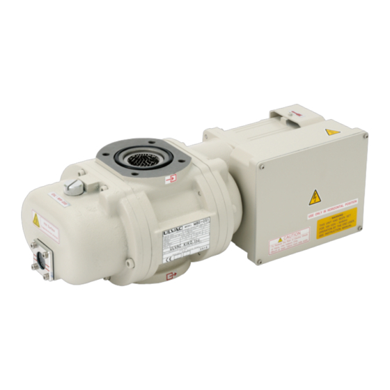
Page 16: Dimensional Drawing (For Mbs-053/Mbs-053-01)
Outside drawing Fig.1 Dimensional drawing of MBS-053/MBS-053-01 mechanical booster vacuum pump. Connecter for external control Internal control/external control SAIE-M12B-4-0.5U-FP-M16 Changeover switch Internal AC Power inlet AC100~120V External AC200~240V AC power 100/200V Change jumper ※The pair of SAIE-M12B-4-0.5U-FP-M16 connector is SAIL-M12G-4-1.5U. -
Page 17: 3. Design Of Vacuum Pumping System
3 .Design of vacuum pumping system 3.1 Pumping system. Cannot use mechanical booster vacuum pump with a unit, and combine it with a backing vacuum pump (Fore Pump) by all means. Note Please do not take evacuation with only mechanical booster pump. A protection feature of a motor works when you perform evacuation only with a mechanical booster pump, and there is it when step out of magnet coupling occurs and, in addition, gives a pump damage of a mechanism. -
Page 18: Fig.3 Basic Piping Diagram To The Vacuum Chamber
Caution Because this pump is complete seal structure. But this pump is for dry air or the dry nitrogen suck only. (MBS-053-01 has surface treatment to MBS-053 and it is increasing resistance to corrosive gases.)Please confirm whether a fore pump supports these gases. It is feared that explosion of a fore pump, When you design an evacuation system, confirm a type of an exhaust-gas, and please execute appropriate plans. -
Page 19: Fore Pump
Fore pump. A normal fore pump to combine to this mechanical booster pump is model GLD-202(201) or GLD-137(136). 130~240L/min is most suitable for pumping speed. Less than 10kPa are necessary for an ultimate pressure. A normal fore pump is oil rotary vacuum pump, but can use a diaphragm pump or a scroll pump, too. -
Page 20: 4.Installation
4.Installation 4.1 Installation of a pump MBS -053/MBS-053-01 becomes design to use in an inline. Fix flange of the outlet side, and install a pump in this flange. Note Install a pump horizontally. Horizontal admissible value of a pump longer direction is ±... -
Page 21: Power Supply Voltage Setting
Note If the pump is operated whilst it is tilted, placed on its side or upside-down, the pump will be damaged. Install the pump level with the inlet facing up as shown in Fig. 1. 4.3 Power supply voltage setting Power supply can operate with 1φAC100 toAC120V (50/60Hz), 1φ... -
Page 22: Electric Wiring
4.4 Electric wiring Power cable is optional parts. When provide in the user side, prepare an electrical cable of the following standard. A plug of a pump side power supply inlet uses an IEC60320-C13 type. Table 2 Power cable selection standards Temperature Supply Voltage Voltage Rating... -
Page 23: A-1) Unplug-Preventive Hardware(Option)
Warning Improper installation of the grounding plug is able to result in a risk of electric shock. When repair or replacement of the cord or plug is required, do not connect the grounding wire to either flat blade terminal. The wire with insulation having an outer surface that is green with or without yellow stripes is the grounding wire. -
Page 24: A-2) How To Install Unplug-Preventive Hardware
Warning Whenever you may operate the vacuum pump with the power cable, does not fail to secure it with the unplug-preventive hardware. a-2) How to Install Unplug-preventive Hardware Install the unplug-preventive hardware in accordance with the procedure as follows: ① Let one end of the unplug-preventive hardware Catch the hole to the side of ②... -
Page 25: Fluctuation In The Power Voltage And Frequency
4.5 Fluctuations in the power voltage and frequency Standard: Rotation electricity machine general rulesIEC60034-1:2004 To the voltage change and frequency change in Domain A, in main rated values, it operates continuously, and can be used practically convenient, and to the voltage change and frequency change in Domain B, it shall operate with main rated values and shall be used practically convenient. -
Page 26: Oil Charge
4.6 Oil charge Remove an oil charge plug to show in Fig.11, and supply with lubricating oil. Lubricating oil uses vacuum-pump oil SMR-200. Refuel it confirm oil quantity with an oil level gauge of Fig.12, and to become between two lines. When corrosive gas is exhausted at MBS - 053 - 01, it is also possible to use fluorine oil (FOMBLIN YLVAC06/6). -
Page 27: 5.Operation
5.Operation Structure of pump Fig.13 Structure of pump This pump has three special features. (1). DC brushless motor⑩ Can run it with the rotating speed that is the optimum which accepted load of a pump by using this motor, and can pump it from atmospheric pressure. -
Page 28: Cautions For Operation
Note Let MBS-053/MBS-053-01 detects load of a pump and a condition of magnet coupling and change operation mode of the motor automatically. Rotation can reduce its speed in process of pumping down, but this is not a failure. Explain details of operation mode as follows. - Page 29 Operation mode 1 Prevention of step out of magnet coupling It is it with-free run till it is it in 1000min rotating speed when torque of a motor goes over moment 0.8N・m. Reduce its speed to 875min at a constant rate afterwards.
-
Page 30: Protection Feature
5.5 Protection feature Protection feature to show for table 3 is incorporated in a protection feature motor driver circuit. When even one protection that showed in table 3 works, it is output as an alarm signal by an outside interface connector. Table 3 Protection feature Protection item Contents... -
Page 31: External Control And Alarm Output
Danger Do not apply more than 150V by setting of the 100V system. Power supply circuit is damaged when you install wrong power supply voltage selection connector and in addition of ignition might. 5.6 External control and alarm output Connector for external control and alarm output is possessed to a motor driver box. -
Page 32: 6.Maintenance
6. Maintenance 6.1 Daily inspection Please execute inspection of table 5. Table 5 Daily inspections Check item Check contents Check interval Is there an oil level between two lines of 1 0il level Once a week level gauge? Cloudiness of oil: Because the moisture of exhaust-gases gets mixed in oil, and ultimate pressure rises, change it in brand new oil. -
Page 33: Trouble Check List
Trouble check list Table 7 Trouble check list Problem Cause Measures Reference ① The pump is not connected ① Connect the pump to the The pump does not to the power supply. power supply. rotate. ② Problem with power supply ②... - Page 34 Problem Cause Measures Reference ⑤ The wire mesh at the inlet ⑤Remove the piping from the pressure port is clogged. upper section of the inlet does not port, and clean the wire decrease. mesh. ⑥ The specified amount of oil ⑥...
-
Page 35: 7.Support In Trouble
Problem Cause Measures Reference ① Deterioration of the O-ring ①Check and replace the O-ring The oil leaks and the oil seal of the case and oil seal. outside the and cover pump. ②Oiling plug or drainage plug ②Close oiling plug or drainage becomes loose plug Nasty smell. - Page 36 Warranty (1) The warranty for this pump (this equipment) extends for a period of one year from the date of shipment. (2) Any malfunctions or defects which occur under normal usage conditions during the warranty period will be repaired free of charge. Note, the warranty stated here is an individual warranty covering the pump.
- Page 37 Usage Status Check Sheet (for use in Instruction Manual) * For the purpose of safety control of repair personnel, fill in within the heavy line frame and attach the sheet to the item of which repair is requested. * In case this sheet were not attached or filled in, your request of repair and service may not be accepted.
Need help?
Do you have a question about the MBS-053 and is the answer not in the manual?
Questions and answers