Table of Contents
Advertisement
No.62500-2-01-8
Instruction Manual
for
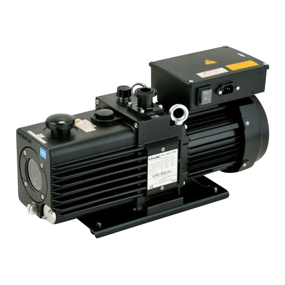
Direct-Drive Oil Sealed Rotary Vacuum Pump
Model
GLD-137CC
GLD-202BB
Before using the product, be sure to read this manual.
Keep this manual in a place where it can be referred to at any time
and look after it carefully.
The contents of this instruction manual are subject to change
without prior notice due to improvements in performance and the
functions of the product.
ULVAC KIKO,Inc.
Advertisement
Table of Contents

Subscribe to Our Youtube Channel
Related Manuals for Ulvac GLD-137CC


Summary of Contents for Ulvac GLD-137CC
- Page 1 No.62500-2-01-8 Instruction Manual Direct-Drive Oil Sealed Rotary Vacuum Pump Model GLD-137CC GLD-202BB Before using the product, be sure to read this manual. Keep this manual in a place where it can be referred to at any time and look after it carefully.
- Page 2 EC Declaration of Conformity ULVAC KIKO,Inc. 291-7 Chausubaru, Saito-city, Miyazaki, 881-0037. Japan In accordance with the following Directive: 2006/42/EC Machinery Directive declare under our sole responsibility that the product, Type of Product : Oil Sealed Rotary Vacuum Pump Model Name...
- Page 3 Power Cable Selection Standards Thank you very much for your purchasing our vacuum pump. This vacuum pump does not have any power cable attached as supplied. It is up to the user to provide an appropriate power cable for your vacuum pump. Please be advised of the standards and precautions that you should use to provide the power cable.
- Page 4 2.2 How to Install Unplug-preventive Hardware Install the unplug-preventive hardware in accordance with the procedure as follows: (1) Let one end of the unplug-preventive hardware catch the hole to the side of the inlet in the interior. (2) While pushing the unplug-preventive hardware at the other end, let it catch the hole to the side of the inlet in the interior.
- Page 5 0. Introduction 0.1 Before using the vacuum pump Thank you for purchasing our vacuum pump (hereinafter called “pump”). When you have received the pump, check that the delivered pump is as per your order and that it has not been damaged in transportation, etc.
-
Page 6: Safety Symbols
0.2 Safety symbols In this instruction manual and on warning labels attached to the pump, the following symbols are used so that matters which must be strictly adhered to can be readily understood. These symbols are divided as shown below. Danger When mishandled, there is an imminent danger of the operator suffering a fatal accident or serious injury. -
Page 7: Cautions For Safety
0.3 Cautions for safety Danger This pump is for dry air or the dry nitrogen suck only. Warning Never allow people other than repair engineers to disassemble or repair the pump. Failure to do so may result in ignition or malfunction, leading to injury or electric shock. - Page 8 Warning Do not use the pump in an explosive atmosphere. Failure to do so will result in injury or fire. Warning When shipping from the factory, the motor is set for 100-120V class. Do not operate with 200-240V power supply voltage. In order to operate with 200-240V class, the changeover switch in the terminal box must be changed into 200-240V class as shown in fig.3.4“Changing the voltage class.”...
- Page 9 Caution If the pump ceases operation or malfunctions, turn off the power switch immediately to prevent accidents, and ask the company from which you purchased the pump or the manufacturer for inspection and repair. Note Do not operate the pump without adding pump oil. If it is operated in an oil-less condition, the pump will be damaged.
-
Page 10: Acceptance And Storage Of The Pump
0.4 Acceptance and storage of the pump 0.4.1 Acceptance of the pump Although the pump is delivered with great care, check the following after unpacking. ① The delivered pump is in accordance with your request. ② The specified accessories (enough pump oil to use the pump once; optional equipment) have been provided. - Page 11 Note When you keep it, without using a pump for a long period of time, please put pump oil into a pump and seal a inlet port. Oil is not put into a pump, but if it is kept where a inlet port is opened wide, water absorption may expand vanes of a pump and a pump may stop rotating.
-
Page 12: Table Of Contents
Contents 0. Introduction ·························· 01 0.1 Before using the vacuum pump ·························· 01 0.2 Safety symbols ·························· 02 0.3 Cautions for safety ·························· 03 0.4 Acceptance and storage of the pump ·························· 06 0.4.1 Acceptance of the pump ·························· 06 0.4.2 Environmental conditions for storage, installation and operation ··... - Page 13 5. Pump Performance ·························· 18 5.1 Ultimate pressure ·························· 18 5.2 Pumping speed ·························· 18 5.3 Power requirement ·························· 18 6. Maintenance, Inspection and Repair ·························· 20 6.1 Maintenance ·························· 20 6.2 Periodic inspection ·························· 20 6.3 Replacement of the pump oil ··························...
- Page 14 Figures and Tables Fig. 1 Dimensional drawing of GLD-137CC oil sealed rotary vacuum pump ······· 4 Fig. 2 Dimensional drawing of GLD-202BB oil sealed rotary vacuum pump ······· 5 Fig. 3 Transportation method of the oil sealed rotary vacuum pump ··········· 6 Fig.
-
Page 15: Introduction
1. For Safe Operation 1.1 Hazards peculiar to the pump and safety measures Before operating or inspecting the pump, read this section carefully to fully understand potential hazards and prevention methods. The pump is not to be used with toxic of flammable gases. 1.1.1 Danger Leakage of hazardous gases and substances Cause... -
Page 16: Caution High Temperature
1.1.4 Caution High temperature Cause Prevention method and measures ⇒ ① The pump reaches a high temperature during operation. High temperatures caused burns. (Temperature increasing) Pump main unit during non-load operation → → 25K Motor during non-load operation Pump main unit during high-load operation → 75K →... -
Page 17: Outline Of The Pump
This oil sealed rotary vacuum pump is a rotary vane pump (hereinafter called Gaede type pump) in which the pump is directly driven by the motor. Since the pump is small, light, and quite simply constructed, it is easily maintained and repaired. Table 1 Specification GLD-137CC GLD-202BB Model Unit... -
Page 18: Dimensional Drawing
2.2 Dimensional drawing Fig. 1 Dimensional drawing of GLD-137CC oil sealed rotary vacuum pump - 4 -... -
Page 19: Fig. 2 Dimensional Drawing Of Gld-202Bb Oil Sealed Rotary Vacuum Pump
Fig. 2 Dimensional drawing of GLD-202BB oil sealed rotary vacuum pump - 5 -... -
Page 20: Installation
3. Installation 3.1 Installation The pump should be installed on a level surface in a location with minimal dust, dirt and humidity and be arranged with consideration given to ease of installation, removal, inspection and cleaning. Particular attention should be paid to the ambient temperature when building the pump into equipment. -
Page 21: Lubrication
3.2 Lubrication Remove the lubrication plug from the lubrication port, and add the pump oil which has been delivered together with the pump or the pump oil specified by us (SMR-100) up to the range marked with the line on the oil level gauge. When making the first lubrication, add oil near to the upper oil level limit shown on the oil level gauge. -
Page 22: Vacuum Piping
3.3 Vacuum piping (1) Before connecting the pipe to the pump, clean the inner walls of the vacuum chamber, piping and vacuum valve to completely eliminate moisture, fine particles, dust, dirt and rust. Note If fine particles, dust or dirt, etc are evacuated, the pump may malfunction. If moisture is evacuated, not only does the ultimate pressure increase but also the inside of the pump becomes rusty causing the pump to malfunction. -
Page 23: Changing The Voltage Class
3.4 Changing the voltage class Voltage class of power sources is changed by the changeover switch in the terminal box. 100-120V class and 200-240V class are prepared. When shipping from the factory, the Voltage class is set for 100-120V class. Fig.6. -
Page 24: Electric Wiring
3.5 Electric wiring (1) The pump rotates in the clockwise direction as seen from the front of the pump (level gauge side). (2) An inlet is suitable for standards of EN60320. (3) Insert an including plug cord into an Inlet as shown in fig.8. (4) Select an power cord which suitable for the voltage class. -
Page 25: Fig. 7 Electric Wiring Diagram
Note This pump must be connected to a grounded, metallic, permanent wiring system, or an equipment-grounding terminal or lead on the product. Fig. 7 Electric wiring diagram Fig. 8 An Inlet (EN60320) - 11 -... -
Page 26: Fluctuation In The Power Voltage And Frequency
3.6 Fluctuations in the power voltage and frequency Standard: Rotation electricity machine general rules IEC60034-1:2004 To the voltage change and frequency change in Domain A, in main rated values, it operates continuously, and can be used practically convenient, and to the voltage change and frequency change in Domain B, it shall operate with main rated values and shall be used practically convenient. -
Page 27: Operation
4. Operation 4.1 Cautions for operation Warning There is a risk of explosion. Never block the outlet or operate the pump with equipment mounted at the outlet side which blocks the passage of gas. Otherwise, the pump internal pressure increases causing the pump to explode, the oil level gauge to protrude or the motor to be overloaded. -
Page 28: Start Of Operation
4.2 Start of operation To start operation, close leak valve (B), open vacuum valve (A) to the inlet port, and turn on the power switch. Then the pump starts beings to exhaust (see Fig. 5). Caution ① The motor and pump become hot (temperature increase under non-load operation: 25K, temperature increase under high-load operation: 75K) during operation of the pump. -
Page 29: Operation In Cold Climates
Caution The motor and pump become hot (temperature increase under non-load operation: 25K, temperature increase under high-load operation: 75K) during operation. There is a risk of burns. Never touch the motor or pump until they have cooled down completely after the pump is stopped. 4.4 Operation in cold climates In winter-season, when operating the pump in cold environment , it will be difficult to start up the pump. -
Page 30: Thermal Protector
4.6 Thermal protector Auto reset thermal protector is incorporated in the motor in order to interrupt the power circuit of the motor and prevent damage to the motor when an over current flows through the motor due to a stop in rotation or overload resulting from the pump malfunctioning during operation. Table 2 Characteristics of the thermal protector Operation temperature 120±5℃... -
Page 31: Installation Of The Oil Mist Trap (Option)
Caution The vacuum pump becomes hot (temperature increase under non-load operation: 25K, temperature increase under high-load operation: 75K) during operation. Do not touch any section other than the valve while the gas ballast valve is in operation. When starting operation, be sure to close the gas ballast valve. Note If the gas ballast valve is left open without condensable gas being exhausted, the pump oil scatters, power is lost, or the ultimate pressure increases. -
Page 32: Pump Performance
5. Pump Performance 5.1 Ultimate pressure The term “ultimate pressure” as employed in the catalogue and in this manual is defined as “the minimum pressure obtained by the pump without the introduction of gas from the pump inlet (i.e. the non-load condition).” For this pump, measurement is performed using the specified pump oil with only a Pirani vacuum gauge installed at the pump inlet port. -
Page 33: Fig. 10 Pumping Speed Curve
Fig. 10 Pumping speed curve - 19 -... -
Page 34: Maintenance, Inspection And Repair
6. Maintenance, Inspection and Repair 6.1 Maintenance Check the following during operation at least once every three days. (1) Amount of pump oil (To be within the range shown with lines on the oil level gauge) (2) Discoloration of the pump oil (3) Abnormal sound (4) Problem with the motor current value (5) Oil leak from the oil seal... - Page 35 Table 3 Periodic inspection table Frequency Item Details Measures Once/3 Amount Refill the oil. days Color (Reddish brown, dark blown, Replace the oil. and cloudy white are not good.) Sound Abnormal sound Check nuts and bolts for looseness. If not clear, contact us. Vibration Abnormal vibration Current...
-
Page 36: Replacement Of The Pump Oil
6) Inspection of the coupling spider Check the spider of the coupling which connects the main pump unit and motor of the pump for damage. If cracks or fractures are found on the spider, replace it in accordance with “6.4 Replacement of the coupling spider.”... - Page 37 Danger Keep in mind that if the pump was used in accordance with its exhausting toxic gas, both the pump unit and pump oil might become contaminated. Caution ① Wear protective equipment such as rubber gloves and safety goggles. ② Be sure to read the attached “Safety Data Sheet” before adding oil. If the oil accidentally comes into contact with your hands or enters your eyes, take proper measures in accordance with the section “First-aid treatment”...
-
Page 38: Replacement Of The Coupling Spider
6.4 Replacement of the coupling spider A rubber spider is used at the section connecting the pump main unit and the motor. It is recommended that this spider be periodically inspected once a year or so. If the corner is chipped or cracked, replace it. -
Page 39: Trouble Check List
6.5 Trouble check list Table 4 Trouble check list Problem Cause Measures Reference ① The pump is not connected to the ① Connect the pump to the power The pump does not rotate. power supply. supply. ② The power switch is not turned on. ②... - Page 40 Problem Cause Measures Reference ⑥ The specified amount of oil has not ⑥ Add the specified amount of oil. The pressure does not been added. decrease. ⑦ The oil has deteriorated. ⑦ Replace the oil. ⑧ Leakage occurs from the pipe ⑧...
-
Page 41: Disposal
7. Disposal Follow state law and local government regulations for disposal of the pump. Caution ① In case a harmful toxic gas has been exhausted by accident, ask a specialist for waste disposal. Not only the pump itself but also the pump oil become toxic. -
Page 42: Maintenance Parts
8. Maintenance parts 8.1 Maintenance parts list Table 5 GLD-137CC Maintenance parts list Product name Parts name Q’ty Outlet valve Outlet valve spring Check valve Check valve spring Oil seal_HTC-17-40-9 Oil seal_SC-17-30-7 Oil seal_SC-15-30-7 O-ring_P-12 O-ring_P-12.5 O-ring_P-35 O-ring_S-5 GLD-137 O-ring_S-12... - Page 43 Table 6 GLD-202BB Maintenance parts list Product name Parts name Q’ty Outlet valve Outlet valve spring Check valve Check valve spring Oil seal_HTC-17-40-9 Oil seal_SC-17-30-7 Oil seal_SC-15-30-7 O-ring_P-12 O-ring_P-12.5 O-ring_P-35 O-ring_S-5 GLD-202 O-ring_S-12 Maintenance kit A O-ring_S-16 O-ring_S-20 O-ring_S-30 O-ring_S-45 O-ring_S-70 O-ring_G-55 O-ring_V-175...
-
Page 44: Disassembly Drawing
8.2 Disassembly drawing Fig. 12 Disassembly drawing of GLD-137CC oil sealed rotary vacuum pump - 30 -... -
Page 45: Fig. 13 Disassembly Drawing Of Gld-202Bb Oil Sealed Rotary Vacuum Pump
Fig. 13 Disassembly drawing of GLD-202BB oil sealed rotary vacuum pump - 31 -... -
Page 46: Warranty
Warranty (1) The warranty for this pump extends for a period of one year from the date of shipment. (2) Any malfunctions or defects which occur under normal usage conditions during the warranty period will be repaired free of charge. Note, the warranty stated here is an individual warranty covering the pump. -
Page 47: Safety Data Sheet (Sds)
Safety Data Sheet --------------------------------------------------------------------------------------------------------------------------------------------- Identification of the Substance/Preparation and of the Company Product Name SMR-100(Mineral oil) Product Code 00001 Supplier ULVAC KIKO, Inc. Address 291-7, Chausubaru, Saito-city,Miyazaki, Japan Tel: 81-983-42-1415 FAX: 81-983-42-1107 Manufacturer MORESCO Corporation. Address 5-5-3, Minatojima-minamimachi, Chuo-ku, Kobe-city, Hyogo, Japan... - Page 48 Date Prepared: May 19, 2015 [Disposal] None --------------------------------------------------------------------------------------------------------------------------------------------- Composition/Information on Ingredients Distinction between Substance and Mixture : Substance Chemical Name/Generic Name : Petro-hydrocarbons Chemical Formula : Not identified Ingredient and Concentration Lubricating base oil 100% ----------------------------------------------------------------------------------------------------------------------------------------------- First-Aid Measures Inhalation: Remove victim to fresh air and let him rinse mouth thoroughly with water. Wrapping a blanket and the like around him to keep warm for a rest, call a doctor/physician immediately.
- Page 49 Date Prepared: May 19, 2015 Accidental Release Measures Personal Precautions, Protective If skin or eye contact is possible, wear protective equipment. If mist Equipment and Emergency Procedures is produced, wear respiratory protective equipment to avoid inhalation. Environmental Precautions Take up as much as possible to avoid soil contamination and water pollution.
- Page 50 Date Prepared: May 19, 2015 Precautions for Safe Handling Obtain special instructions before use. Do not handle until all safety precautions have been read and understood. Be cautious not to use any naked fire. As vapors released from petroleum products are heavier than air, they are liable to stagnate.
- Page 51 Date Prepared: May 19, 2015 protective equipment. Do not eat, drink or smoke when using this product. ------------------------------------------------------------------------------------------------------------------------------------------------ Physical and Chemical Properties Physical State: Appearance Liquid Color Light yellow Odor Slight Oily odor Not applicable Melting/Freezing Point Not applicable Boiling Point 165℃/13Pa(0.1mmHg)...
- Page 52 Date Prepared: May 19, 2015 Carcinogenicity Information is not classified as Carcinogenicity. Reproductive Toxicity Information is not classified as Reproductive Toxicity. STOT/Systemic Toxicity - Information is not classified as Specific Target Organ Toxicity/ Single Exposure Systemic Toxicity (Single Exposure). STOT/Systemic Toxicity – Information is not classified as Specific Target Organ Toxicity/ Repeated Exposure Systemic Toxicity (Repeated Exposure).
- Page 53 Date Prepared: May 19, 2015 1. As evaluations on hazards are not necessary satisfactory, special attention should be paid for use. 2. This SDS, summarizing matters to be attended to, is required for proper use of the product and is intended for normal use.
- Page 54 Usage Status Check Sheet (for use in Instruction Manual) * For the purpose of safety control of repair personnel, fill in within the heavy line frame and attach the sheet to the item of which repair is requested. * In case this sheet were not attached or filled in, your request of repair and service may not be accepted. * In accordance with the Private Information Protection Law, the provided information will be used only for determining the cause of failure and whether detoxifying washing should be conducted.
Need help?
Do you have a question about the GLD-137CC and is the answer not in the manual?
Questions and answers