Table of Contents
Advertisement
Quick Links
Instruction Manual (Original Instructions)
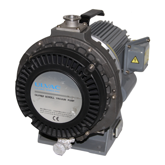
Oil-free Scroll Vacuum Pump
DIS-251
DIS-501
This instruction manual includes very important warnings, cautions and operating
procedure in order to operate this pump safely and efficiently.
Be sure to read this instruction manual thoroughly and fully understand before
operation.
After reading it, store it in a convenient place for immediate and future reading.
Before use, be sure to fill in the blank spaces below for future repair and after-service.
Serial No.
Who sold it to you
Purchase date
When you began
operation
CA72161372(251)
CA72161374(501)
Advertisement
Table of Contents

Related Manuals for Ulvac DIS-251


Summary of Contents for Ulvac DIS-251
- Page 1 CA72161372(251) CA72161374(501) Instruction Manual (Original Instructions) Oil-free Scroll Vacuum Pump DIS-251 DIS-501 This instruction manual includes very important warnings, cautions and operating procedure in order to operate this pump safely and efficiently. Be sure to read this instruction manual thoroughly and fully understand before operation.
-
Page 2: Important Information
Important information Be sure to read this instruction manual to understand how to operate equipment correctly. Only operators, who fully understand warnings, cautions and instructions, are to operate the equipment. Improper operation (mishandling) can cause serious bodily injury, death, fire or explosion. Store this manual in a convenient place for immediate and future reference. -
Page 3: For Safe Operation
We recommend Be sure to turn off electric source on overcurrent protective device (rated 15A building site before wiring. for DIS-251 and rated 15A for DIS-501 If not, it can cause electric shock or bodily Install (rated 20A 100/115V/1-phase)) to protect injury due to turning objects. - Page 4 For safe operation WARNING Danger of short-circuit and Danger of short-circuit and electric shock electric shock Fit firmly proper round type crimp-style Be sure to fit cable-gland to hole of terminal to electric source cable using φ22mm at motor terminal box. Protect cable crimp tool and connect to motor terminal If not, it can cause short-circuit fire or...
- Page 5 4-φ11 holes of pump A v o i d d u s t s o l i d , l e ve l leg (DIS-251) or 4-M10 tap section pump base f l o o r (DIS-501).
- Page 6 For safe operation CAUTION Danger of exceeding permissible Danger of remaining moisture temperature of intake gas When evacuating moisture, be sure to open air-flush port (air-flush opened If intake gas temperature is over 50 ℃ , be operation). sure to install a chiller or trap B e w a r e If you evacuate vapor while air-flush port between vacuum pump and vacuum...
- Page 7 Always keep warning stickers clean and legible. If they become dirty or detached, replace them with new ones. If you need replacement stickers, contact our sales branches who sold the vacuum pump to you. Protection cover Condenser cover DIS-251 Single-phase Beware of electric shock Hour Counter cover Protection cover...
-
Page 8: Table Of Contents
5.2 Maintenance ........................26 6. Problems and remedies ......................27 7. Disposal ..........................27 8. Specifications ........................28 8.1 Specifications ........................28 8.1.1 DIS-251 ........................28 8.1.2 DIS-501 ........................29 8.2 Dimensions ........................30 8.2.1 DIS-251 ........................30 8.2.2 DIS-501 ........................30 8.3 Performance data ...................... -
Page 9: Before Use
If there is any damage, contact either our sales branches who sold it to you or local sales offices. ・ Check the following accessories. Instruction manual (this one) Air-muffler for air-flush (DIS-251 is attached to handle of motor. DIS-501 is attached to eyebolt of motor.) - Page 10 ・ DIS-251 Vinyl bag (Air muffler is contained inside) Serial number ○○ ○○○ Alphabetic Numeric Year of manufacture ・ DIS-501 Vinyl bag (Air muffler is contained inside) Serial number ○○ ○○○ Alphabetic Numeric Year of manufacture ※ Please prepare electric source cables, crimp-style terminal, electric source...
- Page 11 Open package WARNING Danger of cargo collapse Be careful to install vacuum pump using motor handle (DIS-251 mass 25kgs/1-phase, 23kgs/3-phase), or using motor eyebolt and crane with sufficient allowable load capacity (DIS-501 mass 44kgs/1-phase, 38kgs/3-phase) while paying Be careful about attention to stability of suspended load.
-
Page 12: Name And Structure Of Each Section
2. Name and structure of each section ・ DIS-251 Inlet NW25 Handle Turning Direction Plate Fan Cover Motor Hour Counter Air Flush Port (Rc 1/8) Outlet NW16 (It is closed by plug when shipping from factory.) ・ DIS-501 Inlet NW40... -
Page 13: Installation
Necessary ventilated air volume P a y a t t e n t i o n t o DIS-251 DIS-501 ve n t i l a t i o n Over 4 m... -
Page 14: Wiring
Be sure to install on solid and level floor (less than 5° inclination). Uneven installation can cause failure and movement of vacuum pump. If installation floor is unstable, fix pump base with 4- φ 11 holes of pump leg (DIS-251) or 4-M10 tap section pump base (DIS-501). - Page 15 Motor not protected. External overheat protection in accordance with Canadian Electric Code Part Ⅰ [C22.1], must be provided. Min. circuit ampacity of conductor is DIS-251 - 1-phase 10A /3-phase 7A, DIS-501 - 1-phase 18A /3-phase 15A Max. branch circuit breaker is DIS-251 - 15A, DIS-501 - 15A (1-phase 100/115V is 20A) When you used this pump in Europe.
- Page 16 Ground Terminal M5 Bolt Avoid motor burnout by protective device (chart 1). Use rated over electric source cable and earth cord. over rated 10A/1-phase, 7A/3-phase for DIS-251 over rated 18A/1-phase, 15A/3-phase for DIS-501 Cable-gland Use round type terminal. Fit cable-gland.
- Page 17 How to wire ① Remove 4pcs. of M5 bolt at motor terminal box and remove protection cover. ※ Be sure to keep M5 bolts and washer, which were removed from the protection cover. ② Wiring diagram is shown inside protection cover. ③...
-
Page 18: Test Operation
① Open inlet and outlet Blank Flange Remove blank flanges (2 places) from inlet and outlet of vacuum pump. O-ring DIS-251 DIS-501 ② Check turning direction Open inlet, turn on electrical source Turning Direction plate to start operating vacuum pump. Vacuum pump turns clockwise when viewed from motor side. -
Page 19: Connection To Vacuum System (Chamber)
When connecting exhaust piping to outlet of vacuum pump, refer to the following size and length. ・ It is recommended in the case of DIS-251, max. 5m direct pipe length for exhaust pipe size NW16 (inner dia.16) ・ It is recommended in the case of DIS-501, max. 15m direct pipe length for exhaust pipe size NW25 (inner dia.25) But if pipe length becomes longer, use a larger size exhaust pipe. -
Page 20: Operation
4. Operation Be sure to use the procedure below to start up or shut down the pump. ・ When you do not use air-flush device, proceed 4.1 Air-flush closed operation [page 21]. ・ When you use air-flush device, proceed 4.2 Air-flush opened operation [page 22]. WARNING Danger of explosion and ignition Do not evacuate gas which is hazardous to humans or explosive, flammable, or... - Page 21 CAUTION Danger of exhaust disruption Remove blank flange from inlet and outlet. Operation with blank flange being fitted can disrupt exhaust or cause blank flange to fly by Remove blank exhaust impetus, resulting in accident, failure, or bodily injury from contact with flying flange objects.
-
Page 22: Air-Flush Closed Operation
4.1 Air-flush closed operation 4.1.1 Start-up ① Check that blank flange of outlet is removed. ② Close isolation valve in order to prevent the drawback of debris attached to the inside of vacuum pump into vacuum chamber due to pressure differential, resulting in vacuum break and pollution. -
Page 23: Air-Flush Opened Operation
① Stop vacuum pump. ② Remove plug from air-flush port with a spanner (nominal dia. 13mm). ③ Lightly fit the attached air-muffler to air-flush port. ※ Store the removed plug and do not misplace it. DIS-251 Air-flush port Fit air-muffler Remove plug... -
Page 24: Start-Up And Shut-Down
DIS-501 Air-flush port Remove plug Fit air-muffler 4.2.2 Start-up and shut-down ① Start vacuum pump according to 4.1.1 Operation [page 21]. ② Stop vacuum pump according to 4.1.2 Shut-down [page 21]. Important Continuous evacuating of humid gas When evacuating vacuum chamber while humidity in chamber is high, moisture volume drawn into pump differs according to temperature and pressure in chamber. - Page 25 DIS-251 Air-flush port Fit plug Remove air-muffler DIS-501 Air-flush port Remove air-muffler Fit plug -24-...
-
Page 26: Maintenance And Inspection
5. Maintenance and inspection WARNING Danger of failure and bodily injury Conduct periodical maintenance and inspection. If not, it can cause insufficient performance, failure of vacuum pump, and bodily injury. Conduct periodical maintenance and inspection Danger of burns Conduct maintenance and inspection only after vacuum pump becomes cool enough. -
Page 27: Maintenance
5.2 Maintenance When maintenance interval has elapsed, be sure to contact our distributor who sold it to you. This vacuum pump requires maintenance conducted only by our authorized specialist. Never try to disassemble, reassemble or alter on user’s side. We are not responsible for any accidents caused by disassembly, reassembly or alteration which was done by the user or non-specialist. -
Page 28: Problems And Remedies
6. Problems and remedies If something goes wrong, refer to the following chart and remedy problems. If you cannot solve your problems, please contact either our sales branches who sold it to you or local sales. Problems Causes Remedies Protective device (or breaker) ※... -
Page 29: Specifications
8. Specifications 8.1 Specifications 8.1.1 DIS-251 Model DIS-251 50Hz Displacement L/min 60Hz Ultimate pressure Pa ≦ 1.6 Leak tightness Pa ・ m ≦ 1.0x10 Max. inlet pressure Atmospheric pressure Ambient operating temperature ℃ 5~40 Single-phase induction motor Three-phase induction motor,... -
Page 30: Dis-501
8.1.2 DIS-501 Model DIS-501 50Hz Displacement L/min 60Hz Ultimate pressure Pa ≦ 1 Leak tightness Pa ・ m ≦ 1.0x10 Max. inlet pressure Atmospheric pressure Ambient operating temperature ℃ 5~40 Single-phase induction motor Three-phase induction motor, Totally-enclosed, 4-pole, Insulation Class B, IP44 Type Totally-Enclosed, 4-pole, Capacitor start, run,... -
Page 31: Dimensions
8.2 Dimensions 8.2.1 DIS-251 Three-phase Single-phase 8.2.2 DIS-501 Single-phase Three-phase ※Figures in parentheses are dimensions in case that Inlet and outlet are placed vertically -30-... -
Page 32: Performance Data
8.3 Performance data -31-... -
Page 33: Warranty And After-Sales Service
Then attach the complete sheet to the vacuum pump and send it to the service representative. However, please note that ULVAC KIKO cannot repair or inspect the vacuum pump if any gas prohibited in this manual or any gas that gives an adverse effect to the service person was sucked in the vacuum pump. -
Page 34: Vacuum Pump Check Sheet For Repair
6. Miserenious information. Please describe any information if necessary. 7. Send to □Ulvac Kiko,Inc. CS Center. Yokohama Service Dep. 【Address】1-10-4, Kitashinyokohama, Kohoku-ku, Yokohama City, Kanagawa Prf, Japan TEL:045-533-0509 FAX:045-533-0512 □Ulvac Kiko,Inc. CS Center. Miyazaki Service Dep. 【Address】291-7, Chausubaru, Saito City, Miyazaki Prf. Japan TEL:0983-42-4135 FAX:0983-43-2159 ※...
Need help?
Do you have a question about the DIS-251 and is the answer not in the manual?
Questions and answers