Table of Contents
Advertisement
Quick Links
Advertisement
Table of Contents

Related Manuals for Ulvac Desktop YTP


Summary of Contents for Ulvac Desktop YTP
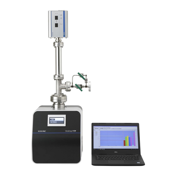
- Page 1 YK18-0012-AI-101-02 ひんやり感 Turbo-molecular-pump Pumping system INSTRUCTION MANUAL MODEL Desktop YTP YTP70A-D Read this manual carefully and use the machine correctly. Keep this manual with care so that you can refer at any time. ULVAC INC, Components Division...
- Page 3 Before Using the Machine We thank you for purchasing a turbo-molecular-pump pumping system: Desktop YTP (hereinafter referred to as "machine") of Ulvac, Inc.(hereinafter referred to as "We") Upon receipt of the machine, please confirm the contents included are the same as you ordered and check the machine for any damage attributed to transportation etc.
-
Page 4: About Safety Notation
Before Using the Machine About Safety Notation In this manual and warning signs on the machine, signal words and symbol marks are displayed in order for you to understand the matters to adhere. The meanings are shown below: ▶ Meaning of signal words: The terms that signify the warning level for safety are referred to as "signal words."... -
Page 5: Types And Display Position On Warning Labels
Before Using the Machine Types and display position on warning labels A warning label is attached onto a warning location on the machine. Never fail to check these labels before operating the machine. ▶ Types and explanation on warning labels Do not operate the machine while attaching a device that may interfere in the passage of gasses on the exhaust port side such as covering the port. -
Page 6: Warranty Clause
▶ How to Respond (a) Domestic: An alternative is delivered or the product is sent back to us or the nearest our ULVAC TECHNO, Ltd. for repair. If it is necessary to respond on site, contact our Components Division, or the nearest sales office or agency for assistance. -
Page 7: Disclaimer
(c) For any questions and consultation on this machine, check the model/serial number and then contact the nearest sales office or agency. https://www.ulvac.co.jp/support_info/ (d) Note that the contents in this document is subject to change without prior notice. About this manual ●... -
Page 9: Table Of Contents
Table of Contents Table of Contents Before Using the Machine ................ i ▶ Meaning of signal words: ..................ii About Safety Notation ......................ii ▶ Meaning of symbol marks: ..................ii ▶ Types and explanation on warning labels..............iii Types and display position on warning labels ............... iii ▶... - Page 10 2.4.11 Alarm pop-up screen ..................17 2.4.12 Numeric key screen ..................17 3. Installation ..................18 3.1 Before installation ......................18 3.1.1 Works from shipment to startup ................18 3.1.2 Environmental condition for storage ..............19 3.1.3 Environmental condition for installation and operation ........19 3.2 Unpacking........................
-
Page 11: For Safe Use
1. For safe use Signifies, by each work, the method for avoiding danger and the actions prohibited to do for dangerousness reasons. 1.1 Handling the machine For an overhaul, repair, or problem on the machine, contact a neighboring service center. Inert gasses (air, nitrogen, and argon) can be discharged with this machine. -
Page 12: Acceptance /Transport / Storage
Contact a nearby sales office or agent. Sales offices list 【 】 https://www.ulvac.co.jp/support_info/sales_office/ 1.2 Acceptance /transport / storage 1.2.1 Acceptance DANGER Do not enter the underside of the machine. If the machine is operated recklessly, or the maintenance is insufficient, the machine may be fell off or toppled down. -
Page 13: Transportation
1.2.2 Transportation For a long-distance transportation, the machine shall be carried by a cargo- WARNING handling device or by a pallet truck. If the machine is transferred for a long distance for such reasons as changing the room to install etc, you may suffer a backache or get injured. For long distance transportation, fix the machine on a cart or a pallet, and use a pallet truck. -
Page 14: Disposal
▶ For safe use NOTES Horizontally install the main unit of the machine If you have the machine tilted, toppled sideways or made upside-down, the machine may be damaged. Horizontally install the machine with the intake port facing upward. NOTES Keeping the environmental conditions This machine includes precise clearances. -
Page 15: Long-Distance Transportation
DANGER Wearing protective gears When doing an inspection or other works, wear a protective gear suitable for the poisonous substance to use. WARNING Entrusting a waste disposer for disposal. Entrust a waste disposer authorized by the administration for disposal works. WARNING Entrust a specialized processor for detoxication processing. -
Page 16: Burst
▶ For safe use 1.6.5 Burst Do not set 0.03 MPaG or more for the exhaust side pressure of the machine. WARNING Measure the pressure on the pump exhaust side and if it is 0.03 MPaG (0.3 kg/cm2G) (gauge pressure) or more, remove the obstacle that blocks the passage of the gas on the exhaust side. -
Page 17: Product Summary
2. Product Summary Desktop YTP is a desktop type high vacuum pumping system equipped with a ceramic ball-bearing type turbo-molecular pump. In consideration of desktop operating environment, the noise and vibration during the operation have been reduced. Moreover, a newly employed touch panel with intelligible display icons enables simple operation. -
Page 18: Names And Works On Each Section
2.3 Names and works on each section ① ⑤ ④ ③ ② ⑥ ⑦ Figure 2 Name of each part Table 1 Name of each part Name Description Intake port Containers or piping for vacuum exhaust are connected. Exhaust port The piping for discharging the exhausted gasses is connected. - Page 19 ▶ Product summary D-IG D-CC D-TMP 1 2 3 4 5 6 D-PG AC-IN CNSIL Figure 3 Name of the connector panel Table 2 Name of the connector panel Name Description It is the primary side power supply input section of the main unit of AC INPUT connector the machine.
-
Page 20: Explanation On Touch Panel Operation Screen
▶ Product summary 2.4 Explanation on touch panel operation screen 2.4.1 Initial screen Turning on the power supply switch displays the initial screen. After passing a few seconds, the operation main screen is switched to appear automatically. ① ① Figure 4 Initial screen Table 3 Explanation of initial screen Name Description... -
Page 21: Vac Screen
▶ Product summary Table 5 Explanation of main screen display Name Description Indicates the status of the machine Rough VAC/Low-vacuum Pumping by FP is running (flickering VAC switch by 0.5 sec) Indication of TMP:ACC / TMP is accelerating (flickering VAC switch by 0.5 sec) operation status TMP:NOR / TMP rated operation is running (turning on the VAC switch light) Waitto STOP / Stop operation is running(flickering VAC switch by 0.5 sec) -
Page 22: Menu Screen
▶ Product summary 2.4.4 Menu screen It is a screen, to be displayed by pressing the Menu switch, for setting various devices. ③ ① ④ ② ⑤ Figure 7 Menu screen Table 7 Explanation of Menu screen switch Turning Tuning off Name Description on light... -
Page 23: P1 Setting Screen
④ Figure 9 P1 setting screen Table 9 Explanation of P1 setting screen Name Description ST2/SH2 The output operation value for ULVAC vacuum gauge G-TRAN is only switch indicated (for high-vacuum). ST2/SH2 <Target devices> combi switch ST2/SH2 only: For using in ST2, SH2 single unit mode. -
Page 24: Etc.1/Etc.2 Screen
▶ Product summary Table 10 Explanation of P2 setting screen Name Description The output operation value for ULVAC vacuum gauge G-TRAN is CCMT-D switch indicated (for low-vacuum). SP1 swtich <Target devices> CCMT-1D,CCMT-10D,CCMT-100D,CCMT-1000D SW1 switch NO USE switch When the P2 display section is not used. - Page 25 ▶ Product summary For the pin assignment when connecting a device other than G-TRAN, refer to the following table. Name PIN No. Description Input of power supply DC 24V Input of device abnormal signal. Normal open. Input of analog signal. DC0-10V D-PG Power supply GND Signal GND...
-
Page 26: Fil Screen
▶ Product summary 2.4.9 FIL screen It is a screen, to be displayed by pressing the FIL switch, for operating the filament of G-TRAN specified in P1. ② ① Figure 12 FIL Screen Table 12 Explanation of FIL screen switch Name Description Turn ON the filament (electric discharge) to start vacuum measurement. -
Page 27: Alarm Pop-Up Screen
▶ Product summary 2.4.11 Alarm pop-up screen When an abnormality is occurred with a device, the name of the device is popped up (Example: Abnormality in TMP). Eliminate the cause of the abnormality following to the device instruction manual. Figure 14 Alarm pop-up screen Table 14 Explanation of Alarm pop-up screen Name Description... -
Page 28: Installation
3. Installation 3.1 Before installation 3.1.1 Works from shipment to startup The work area shall be assumed in that we take on the work area from packing to the shipment (transportation) while the customer takes on from the receipt of shipment to the startup. However, depending on the contract condition of the machine, the customer may take on whole or part of the transportation, unpacking, and installation. -
Page 29: Environmental Condition For Storage
▶ Installation 3.1.2 Environmental condition for storage If the machine is stored in a warehouse or an anterior chamber before installation, or the machine is not used for a long time, store the machine following to the conditions listed below. Ambient temperature From -20 to 60 ℃... -
Page 30: Unpacking
3.2 Unpacking Before being shipped, the machine is protected by stretch film and shock absorbing material etc and packed up with a wooden frame and carton box. For a wooden frame packing, entrust a specialized contractor for disassembly work. Give following cautions and instructions to the disassembly work contractor. 3.2.1 Cautions on unpacking DANGER Do not enter the underside of the machine. - Page 31 ▶ Installation Table 15 Standard accessory list Name Specification Q’ty Remarks ICF: Copper gasket Gasket VG:O ring ISO: Centering Dust cap Inlet port、o port Protective net Only for VG and ICF * The ISO flange is embedded in the gasket. CNSIL connector For CNSIL 3- Jumper pin...
-
Page 32: Transport
▶ Installation 3.3 Transport WARNING Do not tilt the machine for 10 degrees or more. Ignorance to this may cause topple down etc which may end up in injury or damage. For a long-distance transportation, the machine shall be carried by a cargo- WARNING handling device or by a pallet truck. -
Page 33: Piping And Wiring
3.4 Piping and wiring WARNING Shutdown of dangerous energy sources Before working on piping or wiring, refer to "1.For safety use" to check that all the dangerous energy sources have been shut down. The structure of piping and wiring shall be designed so that vibration can be NOTE absorbed. -
Page 34: Gas Purge
▶ Installation 3.4.1 Gas purge To this machine, a gas purge unit can be optionally available and installed. If gasses are discharged, the pump temperature rises, which may affect the bearing service life. (Note 1) If Ar gas of 30 mL/min or more is discharged serially, use the unit. (Note 1) For more details, refer to attached instruction manual on turbo-molecular-pump UTM-70B. -
Page 35: Electric Wiring
3.5 Electric wiring 3.5.1 Electric wiring DANGER A qualified person shall perform a wiring work. A qualified person shall perform electric wiring work. DANGER Before working on a wiring work, turn off the primary side power supply first. Before working on a wiring work, turn off the primary side power supply first. Never perform the work while the voltage is applied. -
Page 36: Operation
▶ Operation 4. Operation 4.1 Cautions on operation Do not suck in non-inert gasses. DANGER Do not use non-inert gasses (toxic gas, combustion gas, combustion- supporting gas, corrosive gas, explosive gas) as this machine is supposed to discharge inert gasses (air, nitrogen, argon) and discharging other gasses may cause leakage of these gasses from the pump main unit, or may cause ignition or explosion inside the pump. -
Page 37: Preparation For Operation
▶ Operation 4.2 Preparation for operation 4.2.1 Check items before operation Before starting the operation, check following matters. 1. For the protection of the machine, the FP is fixed with transportation jigs before the shipment. Remove the transportation jigs before starting up the operation. Keep the transportation jigs with care so as not to lose them. -
Page 38: Startup And Stop Operation Method
4.3 Startup and stop operation method 4.3.1 Startup and stop FP may not start up when the machine is started with vacuum inside. NOTES When the inside of this machine is started in a vacuum state, the FP diaphragm may stick and may not start. In such a case, please restart after restoring the unit to atmospheric pressure. -
Page 39: External Interlock
4.3.2 External interlock As an external interlock for emergency shutdown, this machine contains an interface capable of forcibly shutting down the operation by inputting signals into CNSIL connector 1-2 pin and 3-4 pin Table 17 External interlock pin assignment Connector PIN No. -
Page 40: Connecting G-Tran
It is possible to simply display G-TRAN output operation value by connecting Ulvac transducer type vacuum gauge G-TRAN series to this machine. 4.4.1 Setting of G-TRAN 1.... - Page 41 Table 18 List of connector panel and corresponding G-TRAN models. Corresponding G-TRAN Connector Remarks models For vacuum gauges not requiring filament or turning D-PG SW-1-1、SP1、CCMT-D ON/OFF operation for electric discharge For vacuum gauges requiring filament or turning ON/OFF D-IG SH2-1、ST2-1、SC1 operation for electric discharge For connecting CCMT-D using the cable GDC-xxx for ※...
- Page 42 5. Press Return switch to return to the Main screen. The G-TRAN output operation value specified in P1 and P2 is indicated in the Main screen. *The output operation value of G-TRAN specified in P1 is indicated only while the filament (electric discharge) is turned ON.
- Page 43 1. Check that the operation status is "STOP." Setting for devices cannot be allowed except for "STOP" condition. 2. Connect a corresponding device to any of D-PG, D-IG, or D-CC of the connector panel. D-IG D-CC D-PG AC-IN CNSIL The corresponding connector and display section are as follows. Display Connector Device...
- Page 44 4. Select the function corresponding to the output of the connected device from etc.1 and etc.2 in P1 and P2 of the Menu screen.Check the instruction manual of the connected device and prepare the wiring suitable for the input / output of this unit.Refer to section 2.4.8 for details. Figure20 Menu screen and G-TRAN models on the P1 and P2 screen.
- Page 45 Using filament FIL2 Changing the display unit The display unit can be changed from Pa to Torr or mbar by the following operations. 1. Press and hold the ULVAC logo when the power is on. 2. Press the following switch 3....
-
Page 46: Maintenance And Inspection
▶ Maintenance and Inspection 5. Maintenance and Inspection In order to use the machine safely with keeping the inherent performance, daily and periodical inspection and maintenance are necessary. 5.1 Daily inspection Check following items in order to prevent the machine from breaking down for extending the service life. -
Page 47: Troubleshooting
6. Troubleshooting 6.1 Problem in basic motion Table 19 Problem in basic motion Problems Cause Responding method Reference No electric power is Supply electric power. 4.2.1 supplied. Electric leakage occurred The power supply Contact a service center. inside the machine cannot be turned on. -
Page 48: Alarm State And The Responding Action
▶ Troubleshooting 6.2 Alarm state and the responding action Display Alarm name State Abnormality device P1 ALARM specified in P1 Cause Responding method Reference An abnormal signal is received Handle the matter according to the instruction manual from the device specified in P1. of the device. -
Page 49: Re-Start After Alarm Generation
6.3 Re-start after alarm generation ■ Alarm reset If an alarm is indicated, re-start the machine after eliminating the cause of the alarm. Before re-starting, reset the alarm by any of following methods. Handling after alarm generation Method for resetting alarm After eliminating the cause of alarm, reset In a condition when the characters representing the the alarm and re-start the machine. -
Page 50: Specification
Noise ( ※ dB(A) Input power source Single-phase AC100~240V(50/60Hz) Power capacity Width dimension Length Height ICF:405,VG/ISO:387 ※1: A digit number is expressed. ※2: Without a protective net. ※3: At ultimate pressure. Measured by ULVAC standard for ICF flange type. YK18-0012-AI-101-02... -
Page 51: External Dimensional Drawing
▶ Specification 7.2 External dimensional drawing Inlet Gas purge port Operation screen (option) Outlet Figure 20 External dimensional drawing Inlet flange ICF114 VG65 ISO63-K YK18-0012-AI-101-02... -
Page 52: Appendix
Appendix Main replacement parts The components to be replaced in an overhaul are listed below. The replacement period differs according to the component. The recommended replacement cycle in the following table is presented for reference purpose only. It may be varied according to the use condition and environment of the customer. - Page 54 Model No.:A003S1268-03 ULVAC Component Contamination Certificate This form is used as the Contamination Certificate to make requests for repair/inspection of the ULVAC's components. Before sending your equipment to us such as for repair, fill out this form and submit to the contact request or the representative sales office.
Need help?
Do you have a question about the Desktop YTP and is the answer not in the manual?
Questions and answers