
Related Manuals for Ulvac LR Series


Summary of Contents for Ulvac LR Series
- Page 1 YO02-0872-DI-002-23 MODEL LR-Series/HR-Series 60/90/180/300/600/1200/1800 TYPE DRY VACUUM PUMP INSTRUCTION MANUAL Read this manual before using this pump and keep it hand for immediate reference. Components Division, ULVAC, Inc...
- Page 2 This manual might change for the improvement, the specification change of the product, and the improvement of easiness to use. When you have some ambiguities concerning the operation, please contact with your local ULVAC service center and ask for the matter. Refer to 5.3 Servicing.
- Page 3 If the host equipment of these products does not conform to the same laws, or if the products are modified, then the performance and safety of these products should not be insured. ULVAC should not have a responsibility in such a case. Personnel who have no record of formal safety training course regarded by your government (safety for electricity, cargo handling, etc) should not operate these products.
- Page 4 Safety Denotation For this manual and for warning denotation of LR/HR series models, technical terms are defined according to the hazardous levels, with which workers should understand the rules to be followed. - Articles attached with these denotations, describe countermeasures for potential hazards.
- Page 5 Warning Label Warning labels are attached on the warning locations in this system. Be sure to check them before starting operation of the Pump. Before use, read through the instruction manual and fully understand its contents. ・You may get an electric shock in the area around a portion with this warning label.
- Page 6 LR60/LR90/LR180 LR300/LR600/LR1200/LR1800...
- Page 7 The method for the evasion of danger according to the work item is shown. And the dangerous action, which should not be done, is shown. Installation and Storage Requirements WARNIN ● This product is packed in the wooden crate. Please request dismantlement to a special trader. ●...
- Page 8 Power wiring <Installation> WARNIN ● Before start work, ensure that all hazardous energies are shut off. Refer to 2.1 For Safety Use. ● Wiring work should be performed by licensed workers. ● Use the supplied connectors only. If other connectors are used, the first ground contact may fail, and raise the possibility of electrical shocks.
- Page 9 Suction and exhaust gases <Detaching> WARNIN ● Remove the piping according to the manual provided for the host equipment. ● Suction and exhaust pipe is very hot for some time after pump stop. Remove the protection cover after about one hour after the pump is shut down. ●...
-
Page 10: Table Of Contents
Contents Page 1. Specification ..................... 1 1.1 Overall Configuration ................ 2 1.1.1 Pump Structure ................ 2 1.1.2 System Flow ................4 1.2 Specifications for utilities ..............9 1.3 Dimensional Drawings ..............12 1.4 Description of Controller ..............19 1.5 Utility Panel ..................20 1.6 Performance Curve ................ - Page 11 3.9 Operation ..................68 3.10 stop ....................69 3.11 Self-Diagnostic Function ..............70 3.12 Logging Function ................70 4. Inspection And Maintenance ............... 71 4.1 Inspection ..................71 4.2 Maintenance ..................71 4.3 TROUBLESHOOTING ..............75 4.3.1 Major Troubles ................ 75 4.3.2 In Case of Alarm Signal ............
-
Page 12: Specification
1. Specification Design concept This LR/HR series models are designed to perform vacuum pumping for electronic devices (such semiconductor LCD) manufacturing equipment. Consequently, the interlocking system and control system of this LR/HR series are assumed to be built-in to the host equipment. LR/HR series can be used generally in the following processes: - Chamber vacuum pumping in spattering or vapor deposit processes in which only inert gases (nitrogen or argon) are used. -
Page 13: Overall Configuration
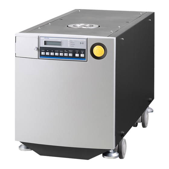
1.1 Overall Configuration 1.1.1 Pump Structure As for a primary pump, the root rotor of six pairs queues up in the series. Casing space is gradually reduced toward the outlet. The booster pump is composed of the root rotor of big capacity by one stage. The two rotors are positioned with a small allowance gap and rotate in opposite directions without contact with each other. - Page 14 The pump is completely clad with panels. The main body of the pump and electrical equipment, the sensor, the N2 adjustment equipment, and the cooling water piping, etc. which drive it are laid out in the package. STOP SWITCH...
-
Page 15: System Flow
1.1.2 System Flow N2, cooling water and power supply is required. Nitrogen gas system Nitrogen gas flows in two lines in the pump, one for the shaft seal and the other for gas ballast (attenuation). The shaft seal prevents lubricating oil from entering the pump casing. Gas ballast gas is fed to the pump casing to reduce corrosion by corrosive gas and accumulation of reactive products, or to reduce liquefaction during the compression and pressurization process of the pump after sucking the... - Page 16 LR300, LR600, LR1200, LR1800 N2 purge gas introduction port SS400 SwegeLock Proper supply pressure :0.1-0.5MPa Set pressure :0.1MPa(Running State) Range of set flowing quantity:0-50SLM Inlet port Seal gas line Outlet port NW40 Proper exhaust pressure:0.1MPa> Exhaust pressure limit :0.12MPa (Absolute pressure) Gas ballast line Cooling water line Cooling water port:Rc3/8...
- Page 17 HR60, HR90, HR180 N2 purge gas introduction port SS400 SwegeLock Proper supply pressure :0.1-0.5MPa Set pressure :0.1MPa(Running State) Range of set flowing quantity:0-50SLM Seal gas line Inlet port Outlet port NW40 Proper exhaust pressure:0.1MPa> Exhaust pressure limit :0.12MPa (Absolute pressure) Gas ballast line Cooling water line Cooling water port:Rc3/8...
- Page 18 HR300, HR600, HR1200, HR1800 N2 purge gas introduction port SS400 SwegeLock Proper supply pressure :0.1-0.5MPa Set pressure :0.1MPa(Running State) Range of set flowing quantity:0-50SLM Inlet port Seal gas line Outlet port NW40 Proper exhaust pressure:0.1MPa> Exhaust pressure limit :0.12MPa (Absolute pressure) Gas ballast line Cooling water line Cooling water port:Rc3/8...
- Page 19 Electrical system has two lines of power line and control line. A sensor is mounted in the system, which is constantly monitoring operation. When the sensor detected abnormal situation, it will activates buzzer, LED and remote control to output warning signal. You can operate the pump using pendant controller for local operation (LOCAL), or using electric signal through the remote controller for remote control (LEMOTE).
-
Page 20: Specifications For Utilities
1.2 Specifications for utilities Specification Spec Model LR/HR60 LR/HR90 LR/HR180 Maximum pumping speed 50Hz 62(1030) 112(1860) 183(3100) m3/hr (L/min) 60Hz 80(1333) 126(2100) 237(3950) Maximum inlet pressure (Pa) Atmospheric pressure Ultimate pressure (Pa) Maximum exhaust pressure Atmospheric pressure Standard VG50 VG80 VG80 Inlet diameter NW40... - Page 21 Utility Requirements 3 phase:200 VAC, 50/60 Hz:220 VAC, 60 Hz Power LR/HR60 LR/HR90 LR/HR180 Model name At max. load (A) 7.0/7.3 11.8/11.8 20.6/21.1 Current LR/HR (60Hz) At ultimate pressure (A) 6.9/7.1 11.2/11.2 18.9/19.6 LR/HR(60Hz) 0.1 to 0.3 Supply pressure (MPa) In/out difference pressure (MPa) Cooling water...
- Page 22 Chemical matters used in this pump Primary pump Pump oil BARRIERTA J100 FLUIDE, J100 FLUIDE E (NOK KLUBER) Bearing grease BARRIERTA JFE552HV (NOK KLUBER) Booster pump (LR/HR300, LR/HR600, LR/HR1200, LR/HR1800) Pump oil BARRIERTA J60 FLUIDE (NOK KLUBER) Above oils are used for bearing lubrication. LR/HR series requires no oil supply for maintenance.
-
Page 23: Dimensional Drawings
1.3 Dimensional Drawings Standard type CE type... - Page 24 Standard type CE type...
- Page 25 Standard type CE type...
- Page 26 Standard type CE type...
- Page 27 Standard type CE type...
- Page 28 Standard type CE type...
- Page 29 Standard type CE type...
-
Page 30: Description Of Controller
1.4 Description of Controller Control Sign Function START switch START Starts the pump. STOP switch STOP Stops the pump. MODE switch MODE Selects a setting item. Changes over the set value. ▽ Input change switch Changes the selected content of setting. △... -
Page 31: Utility Panel
1.5 Utility Panel Standard type CE type No⑪ Inside Controls Sign Functions POWER CNI1 Applies 200VAC power. BREAKER SWITCH (DRP) MCB1 Turns ON/OFF the power. BREAKER SWITCH (MBP) MCB2 Turns ON/OFF the power. Used for remote operation and signal REMOTE CONTROL CNI2 input/output. -
Page 32: Performance Curve
1.6 Performance Curve Pumping speed curve (Primary pump units) Inlet pressure (Pa) Pumping speed curve (Booster pump units) 2000 LR/HR300 Frec.50 LR/HR300 Frec.60 1800 LR/HR600 Frec.50 1600 LR/HR600 Frec.60 LR/HR1200 Frec.50 1400 LR/HR1200 Frec.60 LR/HR1800 Frec.50 1200 LR/HR1800 Frec.60 1000 1.0E-01 1.0E+00 1.0E+01... - Page 33 Current - pressure curve (Primary pump units) 30.0 LR60 HR60 LR90 HR90 25.0 LR180 HR180 20.0 15.0 10.0 1.00E-01 1.00E+00 1.00E+01 1.00E+02 1.00E+03 1.00E+04 1.00E+05 Inret pressure (Pa) Current - pressure curve (Booster pump units) 50.0 LR300 HR300 45.0 LR600 HR600 LR1200 40.0...
-
Page 34: Installation
If the host equipment of these products does not conform to the same laws, or if the products are modified, then the performance and safety of these products should not be insured. ULVAC should not have a responsibility in such a case. Personnel who have no record of formal safety training course regarded by your government (safety for electricity, cargo handling, etc) should not operate these products. - Page 35 Location of vacuum pump in host device Recipience utility from host device Signals centralized N2 gas supervisory Cooling water etc. Electrical interface Power Line HOST Device Control Line Communication Line Vacuum chamber Physical interface Inlet Pipe, Outlet pipe Exhaust Duct Vacuum Pump Utility which does recipience...
- Page 36 Power Wiring This LR/HR series pump is locked out in intercepting cooling water, the N2 gas, and the power line. Give the system which can lock out on the host equipment. Material selection, installation and operation of wiring should be done according to the rules and codes applied in your country (e.g.
- Page 37 << Possible electric shock hazard>> If you have no record of electrical safety training course you should not perform the operation. 1. Shut off the breaker (MCB1, MCB2 (LR/HR300, LR/HR600, LR/HR1200, LR/HR1800)) of the pump. 2. Ensure that LCD of the controller (PCTL) is off. 3.
- Page 38 - The noise filters etc. are used to maintain the tolerance to the electrical noise to these products. The electrical noise (current) is leaked from the noise filter to the ground line. Therefore, a certain earth of the ground line is necessary. - These products are classified with the “High Leakage Current"...
- Page 39 Cooling water - LR/HR series models use cooling water. The products are designed and tested as leakage free for the conditions defined. Nevertheless, for conditions which departed from the criteria (e.g. abnormal high water pressure), may produce leakage. In that case, the leakage will continue unless water supply from the host equipment is shut off.
- Page 40 Suction and exhaust gases. - ULVAC specifies gases which can be exhausted by the pump. When the pump is used to exhaust other gases (e.g. toxic gas, combustible gas, corrosive gas and explosive gas), there could be serious accidents.
- Page 41 Controlling wiring (power supply group units included) - Be careful not to insert things into the fan louver. - A protection circuit should be mounted in the host equipment so that the connector pins of the remote connector not receive voltage higher than 24Vdc. - EMC performance of these products can be obtained under the conditions prescribed by the EMC instruction.
-
Page 42: Installation And Storage Requirements
2.2 Installation and Storage Requirements 2.2.1 Unpack LR/HR series models are packed in wood frames. Unpack work should be performed by expert trades. - This product is packed in the wooden crate. Please request WARNIN dismantlement to a special trader. - Please guide equipment with the glove made of the skin, and the use of an appropriate dismantlement tool to those who dismantle it. -
Page 43: Transit
2.2.2 Transit : Although this pump is provided with casters, do not move it a WARNING long distance using these casters. If you move this pump in such a way, the load exceeds the safety criterion. You could hurt your waist. -
Page 44: Environmental Requirements For Installation
2.2.3 Environmental Requirements for Installation Following installation and storage requirements should be met. Storage and installation requirements Description Requirement Temperature and humidity (for storage) - 30 - 60°C, less than 95%RH Temperature and humidity (for operation) 5 - 40°C, less than 95%RH Above sea level Not exceeding 1000m Outside vibration... -
Page 45: Earthquake Resistant Measures
2.2.5 Earthquake Resistant Measures - To provide earthquake resistance, the pump should be tightly WARNING fixed according to the diagram below. If it is loosely installed, then the pump could topple or move and will produce damages for peripheral devices. - Piping for vacuum, cooling water, nitrogen, and wiring, should be constructed so that they can absorb vibration and should not produce damages on piping or run off within defined vibration... - Page 46 ULVAC, Inc. Components Div. Antiearthquake procedures Date : November 25, 2002 unit LR/HR60 LR/HR90 LR/HR180 LR/HR300 LR/HR600 LR/HR1200 LR/HR1800 The maximum width on surface of projection which falls easily Short distance from fulcrum on surface of projection which falls easily to...
-
Page 47: Piping
: Before start work, ensure that all hazardous energies are shut WARNING off. Refer to 2.1 For Safety Use. - LR series has installed flange for keeping and the suction CAUTION entrance mesh on the suction entrance flange. - HR series has installed flange for keeping on the suction entrance flange. - Page 48 ■ - Installation protection cover to the exhaust heating element. ■- Specification for Connection : refer to 1.3 Dimensional Drawings. ■- Compatible Piping : Use pipe materials which compatible with your local rules and laws concerning to safety. Piping should produce rust.
-
Page 49: Nitrogen Gas Piping
2.3.2 Nitrogen Gas Piping : Before start work, ensure that all hazardous energies are shut WARNING off. Refer to 2.1 For Safety Use. : Use the supplied nuts and ferrule for piping work. ■- Connection Requirements : Swage-lock for 6.35mm-diameter pipe ■... -
Page 50: Cooling Water Piping
2.3.3 Cooling Water Piping : Before start work, ensure that all hazardous energies are shut off. Refer to 2.1 For Safety Use. WARNING - If two or more pumps are used, connect them in parallel, if CAUTION connected serial, then the cooling performance will be reduced and resulted a failure. -
Page 51: Wiring
2.4 Wiring 2.4.1 Power wiring Object model: LR/HR60, LR/HR90, LR/HR180 : LR/HR300, LR/HR600, LR/HR1200, LR/HR1800 : Before start work, ensure that all hazardous energies are shut off. Refer to 2.1 For Safety Use. WARNING Wiring work should be performed by licensed workers. Pin assignment Pin No. -
Page 52: Wiring For Remote Control
System error CLOSE: Normal OPEN: Alarm OUT 24 - 34 COM 1) Do not use it in the LR series. 2) Do not connect to PIN No. 2, 8, 17, 18, 21, 23, 35, 36. Specifications Pump side connector D-sub 37pin female... - Page 53 - Before start the work, ensure that all hazardous energies are shutoff. Refer to the Section 2.1 For safety Use. - Wiring work should be performed by licensed worker. - If the external interlock function is not used (used when an interlock with equipment other than a system in which the pump is installed is activated), connect 1 and 20 by a jumper wire or if the remote emergency stops function (only AC line is shut down) is not used, connect 4 and 22 by a jumper wire.
- Page 54 LR series issues this signal as soon as receiving the signal of pump start, because LR series is not set a temperature. Temperature is not set as standard, but can be set, as and if required.
-
Page 55: Communication
The signal of ready check ( OUTPUT ) 2.4.3 Communication Used when operating the pump using a personal computer or checking the operation history. Contact your local ULVAC service center for the communication functions. Pin assignment Communication specifications Item Signal format... - Page 56 Command Contents Supplement System status read-out Microcomputer status Stop command Start command Status read-out Pump status (normal or abnormal) Valve status read-out Seal gas valve. Gas ballast gas valve. Option valve. Remote/local selection Alarm reset Display read-out at start Pump status by item Alarm log read-out Alarm log up to 30 cases in the past Warning read-out...
-
Page 57: Operation Procedure
3. Operation Procedure 3.1 Flowchart for operation Breaker turn on Pump start SW turn on Motor running N2 solenoid valve open Sensing WARNIG WARNING LED BUZZER Output WARNING Restore it? Sensing ALARM WARNING LED BUZZER Output WARNING Pump stop EMO, EMS SW turn off Motor stop N2 solenoid valve... -
Page 58: Prior Operation
3.2 Prior Operation 1. Ensure that all the piping and wiring works are completed. 2. Open the cooling water valve, and ensure that no water leakage is observed. 3. Turn the nitrogen regulator fully counterclockwise, and open supply valve, and ensure that no nitrogen gas leakage is observed. -
Page 59: Selecting Local (Manual)/Remote
3.3 Selecting LOCAL (manual)/REMOTE Local (manual) operation Switch to use Mode for manual start and stop of the pump Remote operation Mode for starting and stopping the pump by switch operation on the system. The run mode is selected with the REMOTE/LOCAL switch on the controller. -
Page 60: Checking The Pump Run Status
3.5 Checking the Pump Run Status This pump is equipped with multiple sensors, allowing the pump status to be checked on LCD. <Operation> (example) Operation Controller display Turn ON the breaker. CONDITION / STAND-BY Start the pump. CONDITION / Running Display an item to check using N2 Purge Flow 4.3 SLM... -
Page 61: Set Item Change
3.6 Set item change. ● There are two kinds of set items when you change the set item with the pump of UR sires. ● 『SET-UP 1』 is not protected by the password, and set value can be changed according to the specification. ●... -
Page 62: List Of Set Items
Run Mode The pump can be run in the following modes. Mode 1 Both seal gas and gas ballast gas are not used. Mode 2 Seal gas is used, but gas ballast gas is not used. (The solenoid valve opens when the pump starts.) Mode 3 Both seal gas and gas ballast gas are used. - Page 63 MODEL No.6 LR60 Name Alarm Higher/lower Warning Alarm Monitor range limit alarm time time value N2 purge gas Lower limit 5 sec fixed 180 sec 5 sec after run to run alarm stop OP_N2 purge gas Lower limit 5 sec fixed 0 sec 5 sec after run to run alarm...
- Page 64 MODEL No.7 LR90 Name Alarm Higher/lower Warning Alarm Monitor range limit alarm time time value N2 purge gas Lower limit 5 sec fixed 180 sec 5 sec after run to run alarm stop OP_N2 purge gas Lower limit 5 sec fixed 0 sec 5 sec after run to run alarm...
- Page 65 Model No. 8 LR180 Name Alarm Higher/lower Warning Alarm Monitor range limit alarm time time value N2 purge gas Lower limit 5 sec fixed 180 sec 5 sec after run to alarm run stop OP_N2 purge gas Lower limit 5 sec fixed 0 sec 5 sec after run to alarm...
- Page 66 Model No. 9 LR300 Name Alarm Higher/lower Warning Alarm Monitor range limit alarm time time value N2 purge gas Lower limit 5 sec fixed 180 sec 5 sec after run alarm to run stop OP_N2 purge gas Lower limit 5 sec fixed 0 sec 5 sec after run alarm...
- Page 67 Model No. 10 LR600 Name Alarm Higher/lower Warning Alarm Monitor range limit alarm time time value N2 purge gas Lower limit 5 sec fixed 180 sec 5 sec after run alarm to run stop OP_N2 purge gas Lower limit 5 sec fixed 0 sec 5 sec after run alarm...
- Page 68 Model No. 11 LR1200 Name Alarm Higher/lower Warning Alarm Monitor range limit alarm time time value N2 purge gas Lower limit 5 sec fixed 180 sec 5 sec after run alarm to run stop OP_N2 purge gas Lower limit 5 sec fixed 0 sec 5 sec after run alarm...
- Page 69 Model No. 12 LR1800 Name Alarm Higher/lower Warning Alarm Monitor range limit alarm time time value N2 purge gas Lower limit 5 sec fixed 180 sec 5 sec after run alarm to run stop OP_N2 purge gas Lower limit 5 sec fixed 0 sec 5 sec after run alarm...
- Page 70 MODEL No.13 HR60 Name Alarm Higher/lower Warning Alarm Monitor range limit alarm time time value N2 purge gas Lower limit 5 sec fixed 180 sec 5 sec after run to run alarm stop OP_N2 purge gas Lower limit 5 sec fixed 0 sec 5 sec after run to run alarm...
- Page 71 MODEL No.14 HR90 Name Alarm Higher/lower Warning Alarm Monitor range limit alarm time time value N2 purge gas Lower limit 5 sec fixed 180 sec 5 sec after run to run alarm stop OP_N2 purge gas Lower limit 5 sec fixed 0 sec 5 sec after run to run alarm...
- Page 72 Model No. 15 HR180 Name Alarm Higher/lower Warning Alarm Monitor range limit alarm time time value N2 purge gas Lower limit 5 sec fixed 180 sec 5 sec after run to alarm run stop OP_N2 purge gas Lower limit 5 sec fixed 0 sec 5 sec after run to alarm...
- Page 73 Model No. 16 HR300 Name Alarm Higher/lower Warning Alarm Monitor range limit alarm time time value N2 purge gas Lower limit 5 sec fixed 180 sec 5 sec after run alarm to run stop OP_N2 purge gas Lower limit 5 sec fixed 0 sec 5 sec after run alarm...
- Page 74 Model No. 17 HR600 Name Alarm Higher/lower Warning Alarm Monitor range limit alarm time time value N2 purge gas Lower limit 5 sec fixed 180 sec 5 sec after run alarm to run stop OP_N2 purge gas Lower limit 5 sec fixed 0 sec 5 sec after run alarm...
- Page 75 Model No. 18 HR1200 Name Alarm Higher/lower Warning Alarm Monitor range limit alarm time time value N2 purge gas Lower limit 5 sec fixed 180 sec 5 sec after run alarm to run stop OP_N2 purge gas Lower limit 5 sec fixed 0 sec 5 sec after run alarm...
- Page 76 Model No. 20 HR1800 Name Alarm Higher/lower Warning Alarm Monitor range limit alarm time time value N2 purge gas Lower limit 5 sec fixed 180 sec 5 sec after run alarm to run stop OP_N2 purge gas Lower limit 5 sec fixed 0 sec 5 sec after run alarm...
- Page 77 Explanation of Set Items (1) The list above shows the default values of standard settings. (2) This pump gives the following two types of WARNING and ALARM signal. When the number of set value is one and the pump is to be stopped at a certain time The pump displays N Purge Gas if DRP N2 purges gas becomes lower than the...
-
Page 78: Preliminary Operation (Setting Of Utilities)
3.8 Preliminary Operation (Setting of Utilities) Setting of secondary utilities (pump side) should be done after starting the pump. - The maximum exhaust pressure is 0.10 MPa (absolute CAUTION pressure). In excess of this, the seal members may be damaged or overheated, resulting in trouble. -
Page 79: Setting The Seal Gas Flow Rate
3.8.2 Setting the seal gas flow rate The seal gas flow rate is controlled by a fixed orifice. Gas flows at a rate of 5.0 SLM within the range of 0.05 to 0.1 MPa. Regulation is not required. 3.8.3 Setting the gas ballast gas flow rate (in mode 3) After the pump has started, set the gas ballast gas flow rate according to the process. -
Page 80: Stop
3.10 stop Stop the pump. - The pump is very hot during operation and for some time after WARNING it stops. Contact with it may cause burn. Feed cooling water for about one hour after the pump is shut down. Never remove the external panel until the pump cools down. -
Page 81: Self-Diagnostic Function
3.11 Self-Diagnostic Function The operating state is always monitored for the monitor items mentioned earlier. When abnormality occurs Operation Controller display 0. Normal Operation CONDITION/Running 1. If pump operation is continued without meeting the Pump temperature High – requirements, WARNING will be given on LCD and as remote WARNING signal. -
Page 82: Inspection And Maintenance
N2 gas flow at the time of operation. Overhaul or repair work is performed at ULVAC. When any trouble occurs, please contact with your local ULVAC service center (please refer to the ULVAC address list at the end of this manual). - Page 83 < Removal procedure > Power wiring : Shutoff the power securely according to the diagram below WARNING before starting installation or removal work. << Electric shock is possible >> You should not operate this system unless you have electrical safety training course record. 1.
- Page 84 Cooling water Because cooling water in the pump boils when the collaboration of cooling water is removed immediately after the WARNING stop of the pump and pressure rises the sensor and piping might be damaged. Please supply cooling water until the temperature of the pump falls.
- Page 85 Shipping : Although this pump is provided with casters, do not move it a long distance using these casters. If you move this pump in such WARNING a way, the load to move the pump exceeds the safety criterion. You could hurt your waist. When to transit the pump, you should use loading machines (e.g.
-
Page 86: Troubleshooting
Unusual sound is heard from Panel is vibrating Contact with service center pump. Check by ULVAC personnel Exhaust sound Sound may be high due to resonance in the piping when gas is being fed. Use a pipe with a thicker wall to suppress the sound. -
Page 87: In Case Of Alarm Signal
Insufficient supply of gas Increase supply of gas. Clogged piping If the trouble is in the pump, contact with service Leak in joint center. Repair by ULVAC Failure of instrument Contact with service center, repair by ULVAC, WATER Cooling water... - Page 88 Clean and wash piping at CURRENT pressure downstream of pump HIGH Failure of instrument Contact with service ALARM center. Repair by ULVAC Rotation disabled by foreign substance Rotation disabled by low flow rate Rotation disabled by damaged bearing Cut-off of the...
-
Page 89: Warranty Terms
5.WARRANTY TERMS This product is shipped after strict internal inspection. If you find any manufacturing defects, accidents during the transportation, or other defects attributed to our responsibility, please contact our Components Division at headquarters or the nearest sales office or agency. The repair/replacement is free of charge. -
Page 90: How To Respond
(3) For any questions and consultation on this product, check the model/serial number and then contact the nearest sales office or agency, or our Components Division. https://www.ulvac.co.jp/support_info/ (4) Note that the contents in this document is subject to change without prior notice. -
Page 91: Attached Material
Attached material b. About the exchange of FUSE (CE Type) These fuses are set up for the protection of EMI filter (NF31, NF32). The necessity for changing this fuse is not caused usually. Controller's LCD disappears when this fuse cuts, and the pump stops. The replacement procedure of the fuse has been described based on the demand item in UL3101. -
Page 92: Communication System Supplementation
c. Communication system supplementation. c-1 Communication connector connection chart. When communicating by RS-232C. Pin assignment RS-232C TxD RS-232C TxD Pin No Item RS-232C RxD RS-232C RxD 2: RS-232C RxD 3: RS-232C TxD 5: When communicating by RS-485. In case of one. Pin assignment RS-485B(-) RS-485B(-) -
Page 93: C-2 Communication Command
c-2 Communication command. - Page 99 This mark is applied to the electronic information product sold in the People's Republic of China. The figure at the center of the mark is the validity date of environmental protection. This product does not influence the environment, the human body and the property during the period reckoning the manufacturing date as long as the caution for safe use regarding the products are observed.
- Page 100 ULVAC service center or sales office prior to shipment. Please consult with your closest local ULVAC service center or sales office if our components are used with toxic gases or contaminated with reactive products or substances produced by reaction.
Need help?
Do you have a question about the LR Series and is the answer not in the manual?
Questions and answers