Table of Contents
Advertisement
Quick Links
The voltage changeover switch at the time of the delivery is "240".
(The voltage corresponds to 180-253V.)
Application at "90-126V":
Please exchange a voltage changeover switch with "120".
Change the selection at the voltage changeover switch only if the pump is separated from
mains.
Documents are only to be used and distributed completely and unchanged. It is strictly the users´ responsibility to check carefully
the validity of this document with respect to his product.
page 1 of 28
Instructions for use
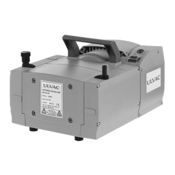
Chemistry diaphragm pump
No. 47900-2-02-5
MD 4UC NT
Advertisement
Table of Contents

Related Manuals for Ulvac MD 4UC NT


Summary of Contents for Ulvac MD 4UC NT
- Page 1 Change the selection at the voltage changeover switch only if the pump is separated from mains. MD 4UC NT Chemistry diaphragm pump Documents are only to be used and distributed completely and unchanged. It is strictly the users´ responsibility to check carefully...
- Page 2 No. 47900-2-02-5 page 2 of 28 Documents are only to be used and distributed completely and unchanged. It is strictly the users´ responsibility to check carefully the validity of this document with respect to his product.
-
Page 3: Table Of Contents
No. 47900-2-02-5 page 3 of 28 Contents Safety information! .....................4 General information ..........................4 Intended use ............................4 Setting up and installing the equipment .....................4 Ambient conditions ..........................5 Operating conditions ..........................6 Safety during operation ........................6 Maintenance and repair ........................8 Technical data ......................9 Gas inlet temperatures ........................10 Wetted parts ............................10 Pump parts ............................10... -
Page 4: Safety Information
No. 47900-2-02-5 page 4 of 28 Safety information! General information ☞ Read and comply with this manual before installing or operating the equip- NOTICE ment. ☞ Transport the pump at the provided handle. Remove all packing material, remove the product from its packing-box, remove the protective covers from the inlet and outlet ports and keep, inspect the equipment. -
Page 5: Ambient Conditions
No. 47900-2-02-5 page 5 of 28 • Comply with maximum permissible pressures at inlet and outlet and pressure differences, see section ”Technical data”. Do not operate the pump with overpres- sure at the inlet. • Check that mains voltage and current conform with the equipment (see rating plate). -
Page 6: Operating Conditions
No. 47900-2-02-5 page 6 of 28 Operating conditions ➨ The pumps have no approval for operation in or for pumping of potentially explosive atmospheres. ➨ The pumps are not suitable to pump unstable substances and substances which react explosively under impact (mechanical stress) and/or when being exposed to elevated temperatures without air, self inflammable substances,... - Page 7 No. 47900-2-02-5 page 7 of 28 • Comply with applicable regulations when disposing of chemicals. Take into con- sideration that chemicals may be polluted. Take adequate precautions to protect people from the effects of dangerous sub- stances (chemicals, thermal decomposition products of fluoroelastomers), wear appropriate safety-clothing and safety glasses. • Use only OEM spare parts and accessories. Otherwise safety and perform- ance of the equipment as well as the electromagnetic compatibility of the equip- ment might be reduced.
-
Page 8: Maintenance And Repair
No. 47900-2-02-5 page 8 of 28 Maintenance and repair Wear parts have to be replaced regularly. In case of normal wear the lifetime of the diaphragms and valves is > 10000 operating hours. Bearings have a typical durability of 40000 h. Motor capacitors have a typical durability in the range of 10000 to 40000 h de- pending strongly on the operation conditions like ambient temperature, humidity or load. -
Page 9: Technical Data
No. 47900-2-02-5 page 9 of 28 Technical data Type MD 4UC NT Maximum pumping speed* 3.4 / 3.8 50/60 Hz (ISO 21360) Ultimate vacuum (absolute) without gas ballast mbar Ultimate vacuum (absolute) with gas ballast mbar Maximum permissible inlet pressure (absolute) -
Page 10: Gas Inlet Temperatures
No. 47900-2-02-5 page 10 of 28 Gas inlet temperatures Permitted range of gas Operating condition Inlet pressure temperatures at inlet Continuous operation > 100 mbar (high gas load) +10°C to +40°C Continuous operation < 100 mbar (low gas load) 0°C to +60°C Short-time (<... - Page 11 No. 47900-2-02-5 page 11 of 28 MD 4UC NT Documents are only to be used and distributed completely and unchanged. It is strictly the users´ responsibility to check carefully the validity of this document with respect to his product.
-
Page 12: Use And Operation
No. 47900-2-02-5 page 12 of 28 Use and operation Installing in a vacuum system • Connection lines at the pump inlet have to be gas tight. Particles and dust must not be aspirated, the user has to provide appropriate filters if necessary. The user must ensure their suitability concerning gas flow, chemical resistance and safe- ness against clogging prior to use. • Connect an exhaust line gas tight at the pump outlet if necessary. Always dispose of exhaust gases appropriately (e.g. into a fume hood). If there is risk of release of dangerous or polluting fluids, install an appropriate system to catch and dispose of those fluids. -
Page 13: During Operation
No. 47900-2-02-5 page 13 of 28 • The gas outlet (hose nozzle 10 mm) must not be blocked. The exhaust pipeline has always to be free and pressureless to enable an unhindered discharge of gases. • If necessary connect the exhaust to a suitable treatment plant to prevent the dis- charge of dangerous gases and vapours to the surrounding atmosphere. During operation • Maximum ambient temperature: 40 °C • Make sure ventilation is adequate especially if the pump is installed in a housing or if the ambient temperature is elevated. -
Page 14: Shutdown
No. 47900-2-02-5 page 14 of 28 For condensable vapours (water vapour, solvents, ...): ☞ Do not pump vapour before pump has reached its operat- ing temperature. Open gas ballast valve when pumping condensable vapours. ☞ The gas ballast valve is open, if the arrow on the gas bal- ballast last cap is pointing towards the labelling ”GB”. -
Page 15: Troubleshooting
No. 47900-2-02-5 page 15 of 28 Troubleshooting Fault Possible cause Remedy ❑ Pump does not start or ➨ ✔ Mains not plugged in, electri- Plug in mains. Check fuse. stops immediately. cal supply failure? ➨ ✔ Device fuse blown? Identify cause of failure. Re- place device fuse. -
Page 16: Replacing Diaphragms And Valves
No. 47900-2-02-5 page 16 of 28 Replacing diaphragms and valves All bearings are encapsulated and are filled with long-life lubricant. Under normal oper- ating conditions, the pump is maintenance free. The valves and diaphragms as well as the motor capacitors are wear parts. If the rated ultimate vacuum is no longer achieved or in case of increased noise level, the pump interior, the diaphragms and the valves must be cleaned and the diaphragms and valves must be checked for cracks or other damage. -
Page 17: Cleaning And Inspecting The Pump Heads
No. 47900-2-02-5 page 17 of 28 Cleaning and inspecting the pump heads The replacement of the diaphragm and the replacement of the valves can be carried out separately. ☞ To replace the valves, remove the head covers of one side of the pump conjointly with the assembled valve heads and fittings. -
Page 18: Replacing The Diaphragm
No. 47900-2-02-5 page 18 of 28 Fittings and tubing MD 4UC NT ➨ Use a Torx screw driver TX20 to unscrew the 4 screws fix- ating the head cover cowling. Pay attention to the washers under the screws and remove. ➨ Pull off head cover cowling carefully. Do not cant. Detach the fixing of the connection tube to the other side of the pump at the valve head. - Page 19 No. 47900-2-02-5 page 19 of 28 ☞ Check diaphragm for damage and replace if necessary. ➨ Lift diaphragm carefully sidewise. ☞ Never use a spiky or sharp-edged tool to lift the dia- phragm. ➨ Use the diaphragm key to grip the diaphragm support disc below the diaphragm.
-
Page 20: Replacing The Valves
No. 47900-2-02-5 page 20 of 28 Replacing the valves ➨ Open the hinged cover of the connection fastener with a flat-bladed screw driver. Loosen connection fastener slightly. ➨ Turn the fillister head screw with a Torx screw driver TX20 one turn at most. ☞ Do not detach the fillister head screw from the square nut. - Page 21 No. 47900-2-02-5 page 21 of 28 ➨ Position valve heads, if applicable with hose nozzle, con- nection tube or connection fastener, and disc springs on the valve seats. Position disc springs with camber up- wards. Pay attention to the correct orientation of the valve heads.
- Page 22 No. 47900-2-02-5 page 22 of 28 ➨ Put head cover cowling on. ➨ Slide the head cover cowling in the grooves of the blinds and under the connection fasteners. ➨ Install the washers. Use a Torx screw driver TX20 to screw in the 4 screws fixating the head cover cowling.
-
Page 23: Replacing The Device Fuse
No. 47900-2-02-5 page 23 of 28 Replacing the device fuse The replacing of the device fuse has to be carried out by an electrician. Switch off the pump and disconnect it from mains before opening the terminal box. After dis- connecting from mains wait two minutes to allow the capacitors to discharge. -
Page 24: Notes On Return To The Factory
No. 47900-2-02-5 page 24 of 28 Notes on return to the factory Repair - return NOTICE Safety and health of our staff, laws and regulations regarding the handling of dan- gerous goods, occupational health and safety regulations and regulations regarding safe disposal of waste require that for all pumps and other products the “Check sheet for repair“ must be send to our office duly completed and signed before any equipment is dispatched to our premises. -
Page 25: Check Sheet For Repair
(3)Ambient temperature: (4)Operational pressure: 6.Miserenious information. Please describe any information if necessary. 7.Send to Ulvac Kiko,Inc. CS Center. Service Dep. 【 Address 】 1-10-4,Kita-shinyokohama,Kohoku-ku, Yokohama,Kanagawa-ken,223-0059,JAPAN TEL:045-533-0509 FAX:045-533-0512 ※Use this paper by recopying for every information. When sending your information without this check sheet, repairing may not be acceptable. - Page 26 No. 47900-2-02-5 page 26 of 28 EC Declaration of Conformity ULVAC KIKO,Inc. 291-7 Chausubaru, Saito-city, Miyazaki, 881-0037. Japan In accordance with the following Directive: 2006/42/EC Machinery Directive 2014/30/EU Electromagnetic Compatibility Directive 2011/65/EU RoHS declare under our sole responsibility that the product,...
- Page 27 1-10-4, Kitashinyokohama, Kohoku-ku, Yokohama-shi, Kanagawa Prf. Japan TEL(81)45-533-0509 FAX(81)45-533-0512 Miyazaki Branch 291-7 Chausubaru, Saito-shi, Miyazaki Prf. Japan TEL(81)983-42-4135 FAX(81)983-43-2159 ULVAC GmbH Parkring 11, 85748, Garching, Germany TEL(49)89-96-0909-0 FAX(49)89-96-0909-96 HEAD OFFICE/ Miyazaki Plant 291-7 Chausubaru, Saito-shi, Miyazaki Prf. Japan TEL : (81)983-42-1411 FAX : (81) 983-42-1422 Documents are only to be used and distributed completely and unchanged.
- Page 28 No. 47900-2-02-5 page 28 of 28 20901389 / 26/01/2018 Documents are only to be used and distributed completely and unchanged. It is strictly the users´ responsibility to check carefully the validity of this document with respect to his product.
Need help?
Do you have a question about the MD 4UC NT and is the answer not in the manual?
Questions and answers