Table of Contents
Advertisement
Advertisement
Table of Contents

Related Manuals for Ulvac ULK-04A


Summary of Contents for Ulvac ULK-04A
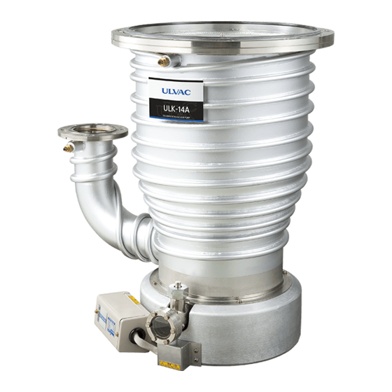
- Page 1 SK00-4802-DI-002-04 No.16.10.20 Instructions Manual Oil Diffusion Pump MODEL ULK-04A ULK-06A ULK-10A ULK-14A Be sure to read the manual before using this product. In addition, keep it in a safe and readily available place. ULVAC, INC. Components Division http://www.ulvac.co.jp/...
-
Page 2: Before Use
SK00-4802-DI-002-04 No.16.10.20 0. Before Use We are sincerely appreciate your decision to purchase our product. Upon receipt of the product, please confirm the contents included are the same as you ordered and check the product for any damage attributed to transportation etc. just in case. This manual describes appropriate ways to handle and maintain the product for the safe use and effective performance. -
Page 3: Safety Symbol Mark
SK00-4802-DI-002-04 No.16.10.20 0.1 Safety symbol mark This instructions manual and the product warning labels indicate safety symbol marks for the understanding of compliance rules. The signs for the symbols are classified as follows. 0.2 Definition of safety symbol mark This indicates an imminently hazardous situation which, if the product DANGER is misused, will result in operator's death or serious injury. -
Page 4: Safety Precautions
SK00-4802-DI-002-04 No.16.10.20 0.3 Safety precautions This section describes a way to avoid dangers and dangerous behavior to be avoided for each work. About this product and this instructions manual To use this product for many years, be sure to read this instructions manual before installation, operation, inspection, or maintenance of DANGER this... - Page 5 (4) Instruct operators to wear leather gloves and use appropriate tools, or they may get injured by broken pieces of crates and nails. Transportation The pump mass is as follows. ULK-04A : 7.5kg ULK-06A : 13.5kg ULK-10A : 47kg ULK-14A : 56kg...
- Page 6 SK00-4802-DI-002-04 No.16.10.20 Seismic countermeasure If not securely fixed, it may turn over or move, damaging the peripheral equipment. Vacuum pipes and electric wires shall be structured not to rapture, not to be disconnected, and to absorb vibration by a specified W ARNING vibration.
- Page 7 SK00-4802-DI-002-04 No.16.10.20 Operation (1) During the operation, do not touch the vacuum pump body, heater, and pipes since they are subjected to high temperature. If your body comes into contact with them, you may get burned. (2) Do not operate the vacuum pump with any devices that cause clogging of the exhaust attached on the exhaust port side in such a way that W ARNING they disturb the gas flow.
- Page 8 Be sure to supply water during the operation. The required amount of cooling water is as follows: ・ Amount of cooling water ULK-04A/D-11(0.55kW) : 1.0 L/min or more ULK-04A/D-31(0.73kW) : 1.0 L/min or more ULK-06A/D-11(0.9kW) : 1.0 L/min or more ULK-06A/D-31(1.2kW) : 1.5 L/min or more...
- Page 9 W ARNING removing it. Fully seal the intake and exhaust ports using shutoff flanges etc. Transportation The pump mass is as follows. ULK-04A : 7.5kg ULK-06A : 13.5kg ULK-10A : 47kg ULK-14A : 56kg W ARNING For transfer, loading equal to or higher than the safety standards is necessary depending on the model and you may damage your back.
-
Page 10: Type/Description And Position Of Warning Label On This Machine
SK00-4802-DI-002-04 No.16.10.20 0.4 Type/Description and position of warning label on this machine On this machine, warning labels are attached to the points to warn. Be sure to check before operating the pump. In the area around where this warning label is attached, you may get an electric shock. -
Page 11: Acceptance And Storage Of Pump
SK00-4802-DI-002-04 No.16.10.20 0.5 Acceptance and storage of pump 0.5.1 Acceptance of unpacked pump (1) This product is paced in a wooden crate. Please ask a professional contractor to dismantle it. During the work, there is the risk of cutting your hands by nails or wooden chips used to fix the wooden crate. Therefore, instruct the person who dismantle the crate to wear leather gloves and use an appropriate dismantling tool, such as a crowbar. -
Page 12: Transportation
In the event of a failure, contact our sales department or your special agency. 0.5.2 Transportation The pump mass is as follows. ULK-04A : 7.5kg ULK-06A : 13.5kg ULK-10A : 47kg ULK-14A : 56kg W ARNING For transfer, loading equal to or higher than the safety standards is necessary depending on the model and you may damage your back. -
Page 13: Ambient Conditions During Storage, Installation, And Operation
SK00-4802-DI-002-04 No.16.10.20 0.5.3 Ambient conditions during storage, installation, and operation This product is a machine with precision clearances. Therefore satisfy the following conditions during the storage, installation, and operation. Corrosive and explosive gas are not allowed. Freeze and condensation is not allowed. Dust is not allowed. -
Page 14: Protective Equipment
SK00-4802-DI-002-04 No.16.10.20 0.6 Protective equipment This machine comes equipped with a single-phase heater for 200 VAC or 220 VAC. This heater has no protection equipment. Be sure to connect the heater to the power supply through an overload protector. The electrical equipment technical standards (The government ordinance No. -
Page 15: Table Of Contents
SK00-4802-DI-002-04 No.16.10.20 Table of Contents 0. Before Use ........................i 0.1 Safety symbol mark ........................ ii 0.2 Definition of safety symbol mark ..................... ii 0.3 Safety precautions ......................... iii 0.4 Type/Description and position of warning label on this machine ..........ix 0.5 Acceptance and storage of pump ................... - Page 16 SK00-4802-DI-002-04 No.16.10.20 4.2 Operation start ........................24 4.3 Operation stop ........................26 5. How to Handle Thermostat (Option) ................27 6. Maintenance/ Inspection ....................28 6.1 Maintenance ........................28 6.2 Periodical Inspection ......................28 6.2.1. Oil level ......................................29 6.2.2. Inspection of vacuum pump oil ............................29 6.2.3.
- Page 17 Drawing List Figure 1: Part name of ULK type oil diffusion pump .................. 6 Figure 2: Oil diffusion vacuum pump Model No.ULK-04A, Dimensional appearance drawings .... 9 Figure 3: Oil diffusion vacuum pump Model No. ULK-06A, Dimensional appearance drawings ..10 Figure 4: Oil diffusion vacuum pump Model No.
-
Page 18: For Safe Use
Injury during the pump transportation. Mass of the pump (2) Unreasonable operation or insufficient ULK-04A : 7.5 kg maintenance of equipment may cause the pump ULK-06A : 13.5 kg to fall or turn over. Never get under the pump. ULK-10A : 47 kg... -
Page 19: Electric Shock
SK00-4802-DI-002-04 No.16.10.20 1.1.3 Electric shock WARNING Factor How to avoid / Measure (1) Before establishing electrical connections, be sure to turn off the power. Be sure to connect to ground. (2) Be sure to close the cover of the heater terminal box first and then operate the pump. -
Page 20: Leakage Of High-Temperature Cooling Water
(1) For the auxiliary pump, use one that has sufficient pumping performance. Critical back pressure (2) Do not operate this unit with the outlet clogged ULK-04A(D-11):40Pa or with any equipment installed on the outlet ULK-04A(D-31):60Pa side which prevents gas from passing. -
Page 21: Explosion
SK00-4802-DI-002-04 No.16.10.20 1.1.7 Explosion WARNING Factor How to avoid / Measure This pump is not designed for pressurization and, if pressurized, may burst, scattering broken pieces. The pump's internal pressure Do not pressurize not only during the operation but increases and the pump bursts. also under any circumstances. -
Page 22: Material Safety Data Sheet (Sds)
SK00-4802-DI-002-04 No.16.10.20 1.2 Material safety data sheet (SDS) Chemicals used for this pump (1) ULVOIL D-11 (2) ULVOIL D-31 IMPORTANT The material safety data sheet describes the hazards and harmfulness of the chemical substances, measures against them, etc. which may be used or come into contact with operators for operation of this unit. -
Page 23: Overview
SK00-4802-DI-002-04 No.16.10.20 2. Overview 2.1 About oil diffusion pump The principle of an oil diffusion pump is that gas molecules coming into the pump inlet are captured by injected stream and flow downstream with the injected stream. The gas molecules flowing downstream by the injected stream cannot pass through the thick upstream layer of injected stream and further flow downstream. -
Page 24: Performance Specifications
SK00-4802-DI-002-04 No.16.10.20 2.2 Performance specifications Table 1 Performance specifications Model ULK-04A ULK-06A Specification ULVOIL ULVOIL ULVOIL ULVOIL D-11 D-31 D-11 D-31 Pump Power*1 0.55 0.73 0.90 Ultimate pressure <2.6×10 <2.6×10 <2.6×10 <2.6×10 Maximum forepressure Evacuation speed 1200 1100 Maximum air outlet Pa・... - Page 25 SK00-4802-DI-002-04 No.16.10.20 Graph 1: Pumping speed curve for ULK-04A/ULK-06A Graph 2: Pumping speed curve for ULK-10A/ULK-14A...
- Page 26 SK00-4802-DI-002-04 No.16.10.20 Figure 2: Oil diffusion vacuum pump Model No. ULK-04A, Dimensional appearance drawings...
- Page 27 SK00-4802-DI-002-04 No.16.10.20 Figure 3: Oil diffusion vacuum pump Model No. ULK-06A, Dimensional appearance drawings...
- Page 28 SK00-4802-DI-002-04 No.16.10.20 Figure 4: Oil diffusion vacuum pump Model No. ULK-10A, Dimensional appearance drawings...
- Page 29 SK00-4802-DI-002-04 No.16.10.20 Figure 5: Oil diffusion vacuum pump Model No. ULK-14A, Dimensional appearance drawings...
-
Page 30: Mounting
SK00-4802-DI-002-04 No.16.10.20 3 Mounting Please read "0.5 Pump acceptance and storage" and check the pump for any defects. Install and operate this product according to the local and national safety laws and regulations (such as fire laws and electric wiring code). Accordingly, you are required to take classes for general safety that are valid in the country and the local area at the site. -
Page 31: Oil Filling
3.2 Oil filling (1) Prepare a well washed and dry graduated cylinder (500 to 1,000cc). (2) Pour the specified amount (ULK-04A: 150cc; ULK06A: 350cc, ULK-10A: 800cc, ULK-14A: 1,500cc) of given oil (ULVOILD-11 or ULVOIL D-31) into the graduated cylinder. (3) Pour oil into the air outlet. -
Page 32: Water Piping
For the cooling water, see Table 1. The cooling water inlet and outlet is ULK-04A/ULK-06A: Rc1/4, ULK-10A/ULK-14A: Rc3/8. Attach the joints for water piping (nylon tubes etc.) to install the piping. -
Page 33: Intake Port Pipe (Connection To Vacuum Chamber Side)
SK00-4802-DI-002-04 No.16.10.20 (1) It is designed to cause no leakage under the specified condition and water leakage tests have been done. However water leakage may occur under abnormal conditions outside the specifications (such as an abnormal increase in water pressure). In such a case, unless the supply from the unit stops, the water leakage continues. -
Page 34: Exhaust Port Pipe (Piping To Auxiliary Pump)
SK00-4802-DI-002-04 No.16.10.20 Install a valve on the way to the vacuum chamber. CAUTION When stopping this unit, keep the inside of this unit in vacuum. 3.5 Exhaust port pipe (Piping to auxiliary pump) (1) Thoroughly clean the inside of the piping, vacuum valves, etc. and then connect to the pump. If it is connected under a dirty condition, the ultimate pressure becomes higher or the time required for the pressure to decrease down to a given pressure becomes longer. - Page 35 SK00-4802-DI-002-04 No.16.10.20 (1) For a leak valve on the outlet port side with respect to this unit, install as near the auxiliary pump as possible. (2) Install a valve on the way to the auxiliary pump. When stopping this unit, keep the inside of this unit in vacuum. CAUTION (3) Install a vacuum gauge on the way to the auxiliary pump in order to monitor the back pressure.
-
Page 36: Electric Connection
Table 2: Oil diffusion vacuum pump: Current value of ULK series Power Current value (A)*1 consumption of Model number Oil type heater 1φ 200V 1φ 220V (KW) ULK-04A 0.55 ULVOIL D-11 ULK-04A 0.73 ULVOIL D-31 ULK-06A ULVOIL D-11 ULK-06A ULVOIL D-31... - Page 37 The terminal of ① and ② leads to thermostat. Note: The thermostat is an option. Figure 6: Connection of outside lines to terminal box for ULK-04A/ULK-06A Thermostat Connect electric wires to terminal ③ and ④. The terminal of ① and ② leads to thermostat.
- Page 38 SK00-4802-DI-002-04 No.16.10.20 Install and operate this product according to the local and national safety laws and regulations (such as fire laws and electric wiring code). W ARNING (1) Before connecting electric wires, be sure to turn off the power switch. Never do this work with voltage applied.
-
Page 39: Operation
Be sure to supply water during the operation. The required amount of cooling water is as follows: ・ Amount of cooling water ULK-04A/D-11(0.55kW) : 1.0 L/min or more ULK-04A/D-31(0.73kW) : 1.0 L/min or more ULK-06A/D-11(0.9kW) : 1.0 L/min or more CAUTION ULK-06A/D-31(1.2kW) : 1.5 L/min or more... - Page 40 SK00-4802-DI-002-04 No.16.10.20 (1) Depending on the use, the vacuum pump oil may deteriorate in a quite short period of time. It is recommended to do the first replacement of the vacuum pump oil within 10 days, evaluate the degree of contamination of oil, and then determine the oil replacement cycle.
-
Page 41: Operation Start
SK00-4802-DI-002-04 No.16.10.20 4.2 Operation start Check the following items again before operating the pump. (1) Check that the piping and wire connections are complete. (2) Leak check The pump-specific leak check is performed by a helium leak detector. The detectable minimum leak is 6.5 × 10 /s (5 ×... - Page 42 SK00-4802-DI-002-04 No.16.10.20 (1) Do not turn on the power to the heater with no supply of cooling water. Turning on the power to the heater without supplying cooling water may cause damage to the pump as follows: A break is caused in a heater cable. Solder on the cooling water piping dissolves and falls.
-
Page 43: Operation Stop
SK00-4802-DI-002-04 No.16.10.20 4.3 Operation stop Turn off the power to the heater switch of the oil diffusion pump. Close the valves on the inlet (above this unit) and outlet (below this unit) sides. If no valves are supplied, continuously operate the oil rotary pump for approx. 70 minutes until the oil temperature becomes 150℃... -
Page 44: How To Handle Thermostat (Option)
No.16.10.20 5. How to Handle Thermostat (Option) Thermostat (1) Set temperature: :250℃(ULK-04A,ULK-06A) 180℃(ULK-10A,ULK-14A) (2) Contact arrangement: Open at set temperature (NORMAL CLOSE) (3) Switching capacity: 1,000W AC115/220V A thermostat attached to the ULK series as an option is a device in which a contact is opened/closed by the thermal expansion of a metal cylinder. -
Page 45: Maintenance/ Inspection
SK00-4802-DI-002-04 No.16.10.20 6. Maintenance/ Inspection 6.1 Maintenance (1) During the operation, check the following items at least once every three days. (2) Is the oil level sufficient? (See Section 2.2 Performance specifications.) (3) Is the vacuum pump oil discolored? (4) Does a specified amount of cooling water flow? (See Section 2.2 Performance specifications.) (5) Is there any point of water leakage? (6) Is there an anomaly in the current value? (See Section 2.2 Performance specifications.) (7) Is there any anomaly in the ultimate pressure in the vacuum area higher than this unit, and in the... -
Page 46: Oil Level
In oil replacement, be sure to pour the specified amount of oil using a graduated cylinder etc. Model No. ULK-10A and ULK-14A are equipped with inspection windows. Model No. ULK-04A and ULK-06A are not equipped with inspection windows. 6.2.2. Inspection of vacuum pump oil The vacuum pump oil is not only contaminated by suction gas but also degraded gradually as the temperature increases during the pump operation. - Page 47 SK00-4802-DI-002-04 No.16.10.20 For ULK-10A,ULK-14A Drain of working fluid (See Fig. 9) (1) After stopping the pump following Section 4.3, check that the pump and oil are at a normal temperature again and then return the pressure in the pump to the atmospheric pressure. (2) Prepare an aluminum foil (approx.
- Page 48 SK00-4802-DI-002-04 No.16.10.20 Oil filling (See Fig. 9) (1) Remove the cap nut ⑤. (2) Remove the packing retainer ⑥ and the metal packing ⑦. (3) As shown in (D), set a clean funnel at the oil filler port. (4) Pour a specified amount of oil. (5) After the completion of oil filling, attach the cap nut ⑤, packing retainer ⑥, and metal packing ⑦.
- Page 49 SK00-4802-DI-002-04 No.16.10.20 Oil leak check In the event of oil leakage from the oil filler or drain ports etc., the gasket needs to be replaced and re-tightened. The seals used for this unit are available at the nearest service center described at the end of this document.
-
Page 50: Disassembling Of Pump
(4) Hold the 1st steam tower ⑬ just under the hot cap ⑫ and pull up the nozzle ⑨. (5) Remove the fractionating plate ⑩ and the nozzle fixing ring ⑪. In ULK-04A, the nozzle fixing ring ⑪ and the fractionating plate ⑩ are integrated. (6) For the nozzle system, pinch the 1st steam tower ⑬... - Page 51 ※2 Fractionating plate ※2 Nozzle fixing ring *1: The bearings and the shaft are swaged. *2: In ULK-04A, the nozzle fixing ring and the fractionating plate are integrated. Figure 10: Nozzle pull-out instruction diagram for ULK-04A, ULK-06A Name Hot cap...
- Page 52 SK00-4802-DI-002-04 No.16.10.20 For ULK-10A,ULK-14A Removal of pump from line (1) Remove the electric wires from the terminal box. (2) Remove the thin flex tubes for cooling water. (3) Remove the tightening bolts for the inlet and outlet port flanges embedded in the system. (4) Place the removed pump on a flat surface.
- Page 53 SK00-4802-DI-002-04 No.16.10.20 Name Plain washer: For M5 Hexagon socket head bolt M5 × 16 Hexagon nut: M5 Hexagon nut: M5 (ULK-14A only) Hexagon socket head bolt M5 × 16 (ULK-10A only) Plain washer: For M5 Cold cap support beam (C) Cold cap support beam (B) Pump case Hexagon socket head bolt M5 ×...
- Page 54 SK00-4802-DI-002-04 No.16.10.20 Name Hot cap Plain washer: For M5 Hexagon nut: M5 Fixing ring Distance pipe Screw: M5 Thermal radiation plate 1st steam cylinder Figure 13: Exploded diagram of 1st steam cylinder for ULK-10A, ULK-14A...
-
Page 55: Cleaning Of Pump
Assemble the nozzles in reference to Figs. 10 to 13 in the reverse order of disassembling of the nozzles. However, pay attention to the following: For ULK-04A,ULK-06A When inserting the nozzles into the pump case, set them so that the four set screws on the fixing ring are inserted into the outermost notches on the nozzles. -
Page 56: Attachment Of Pump In The Line
SK00-4802-DI-002-04 No.16.10.20 6.2.7 Attachment of pump in the line (1) Pour the specified amount of oil from the air inlet or outlet. (2) Attach the air inlet flange and the air outlet flange in the line. (3) Attach the thin flex tubes for cooling water. (4) Connect the electric wires to the terminal box. - Page 57 (4) Removal of the nut in 4-2 allows you to remove the reflector ⑤, whereas removal of the other nut in 4-1 allows you to remove the heater ②. (5) Remove the thermo cement adhering to the bottom of the pump case. Figure 14: Diagram on removal of heater of ULK-04A, ULK-06A...
- Page 58 ③ Heater terminal ③ヒータ端子 ③ヒータ端子 ①ターミナルボックス内部端子 ①ターミナルボックス内部端子 Heater 200V 1φ 200V 1φ ヒータ源 ヒータ源 source (220V (220V 1φ) 1φ) ④ ④ ② ② Note: The thermostat is an option. Figure 16: Wiring work instructions in terminal box for ULK-04A, ULK-06A...
-
Page 59: Attachment Of New Heater
SK00-4802-DI-002-04 No.16.10.20 6.2.9 Attachment of new heater For ULK-04A,ULK-06A See Figs. 14 (1) On the side where the heater pump is attached, spread evenly thermo cement of 1 to 2mm in thickness across the front surface. (2) Set the heater ② to the mounting position and securely tighten the nut 4-1. -
Page 60: Inspection After Storage For Long Period Of Time
SK00-4802-DI-002-04 No.16.10.20 For ULK-10A,ULK-14A See Figs. 15, 16. (1) Figure 15 Attach the parts ① to ⑮ in the numerical order. At this point, spread evenly thermo cement of 1 to 2 mm in thickness across the side where the heater pump is attached. Remove the thermo cement coming out of the joint surface between the heater and the pump. -
Page 61: Trouble Check List
SK00-4802-DI-002-04 No.16.10.20 6.5 Trouble check list Table 3: Trouble check list Problem Cause Measure Ref. Pressure does not (1) Improper wire (1) Check the wire connections. decrease. connections Pressure varies (2) Improper setup of safety (2) Set the safety circuits to the circuits for heater specifications. - Page 62 SK00-4802-DI-002-04 No.16.10.20 Problem Cause Measure Ref. Pressure does (11) The pipe diameter in the (11) Use pipes with a sufficient 3.4~ not decrease. section to the ancillary conductance. pump. Pressure varies (12) The valves on the high (12) Open the valves. 3.4~ vacuum and ancillary pump sides are closed.
- Page 63 SK00-4802-DI-002-04 No.16.10.20 Problem Cause Measure Ref. Cooling water (1) The connectors in use are (1) Connector does not flow at small in inner diameter. the specified quantity. (2) Cooling water pipes are (2) Replace the cooling water pipe thin. with a thick one. (3) Cooling water pipes are (3) Shorten as much as possible.
-
Page 64: Disposal
SK00-4802-DI-002-04 No.16.10.20 Problem Cause Measure Ref. The thermostat (1) Low oil level (1) Supply oil. reacts. No oil Disassemble and inspect in the 6.2.1~ Being heated without water case of heating without water. 6.2.7 Overhaul Note 1 The thermostat is an option. -
Page 65: Warranty Clauses
This product was shipped after rigid company inspection. However, in case any failure occurs under ULVAC’s responsibility, such as defect in manufacturing and damage during transportation, Buyer shall inform ULVAC, Inc. or the local ULVAC representatives. ULVAC will repair or exchange it at free of charge. -
Page 66: Response Procedure
8.4 Response procedure (1) Domestic business in Japan: ULVAC send a replacement or Buyer return the defective items to ULVAC, Inc. or to the local ULVAC representatives for repair. If field service is required, Buyer shall ask ULVAC, Inc. or the local ULVAC representatives. -
Page 67: Main Replacement Parts
SK00-4802-DI-002-04 No.16.10.20 9 Main Replacement Parts Table 4: List of main replacement parts Material Shape/Dimensions Remarks ULK-04A 4×4×I.D120 Nitrile rubber or ULK-06A 4×4×I.D175 Air inlet gasket fluorine-contained ULK-10A 8×8×I.D275 rubber ULK-14A 8×8×I.D380 ULK-04A W4×I.D39.5 Nitrile rubber or Air outlet gasket... - Page 68 Format No.:A003S1268-01 ULVAC Component Pollution Certificate This is the certificate to make requests for repairs/inspections of ULVAC's components. Before sending back your own equipment to us, complete this certificate and submit it to our departments in charge of your requests or individual sales offices.
- Page 69 This mark is applied to the electronic information product sold in the People's Republic of China. The figure at the center of the mark is the validity date of environmental protection. This product does not influence the environment, the human body and the property during the period reckoning the manufacturing date as long as the caution for safe use regarding the products are observed.
Need help?
Do you have a question about the ULK-04A and is the answer not in the manual?
Questions and answers